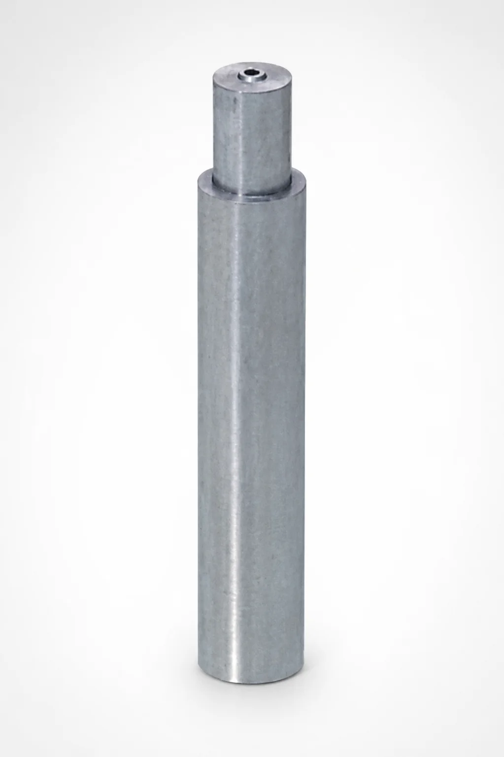
JIS Standard SKH51 Steel Pin-Point Gate Bushings Round Gate Transition SR
Pin-Point Gate Bushings (SKH51 steel) with Round Gate Transition and SR tip step shape are designed to guide molten material into the mold gate smoothly, reducing gate disruption and improving process consistency. Built for dependable performance under repeat injection cycles.
- Round gate transition geometry supports stable melt flow during molding
- SKH51 steel hardened wear construction improves longevity in production
- Maintains tight P dimension tolerance (±0.01) for precise gate alignment
- SR tip step shape helps achieve consistent pin-point gate formation in dies
Specifications
55 configurations available
| Tip Type | Tip Shape | P Dimension Tolerance | Tip Straight Tolerance | D (Outer diameter) (mm) | A (Taper angle) (°) | C (Tip length) (mm) | K (Cutting angle) (°) | L (L dimension) (mm) | P (Tip diameter) (mm) | R (Tip R) (mm) | S (Tip angle) (°) | V (Tip diameter) (mm) | type |
|---|---|---|---|---|---|---|---|---|---|---|---|---|---|
| Normal | 1A | ±0.01 | 0 to 0.2 | 2 | 1 ~ 3 | 0.2 ~ 0.4 | 20 ~ 30 | 6 ~ 20 | 0.3 ~ 0.5 | - | - | 1.3 ~ 1.9 | - |
| Normal | 1A | ±0.01 | 0 to 0.2 | 2.5 | 1 ~ 3 | 0.2 ~ 0.5 | 20 ~ 30 | 8 ~ 25 | 0.3 ~ 0.6 | - | - | 1.5 ~ 2.4 | - |
| Normal | 1A | ±0.01 | 0 to 0.2 | 3 | 1 ~ 3 | 0.3 ~ 0.8 | 20 ~ 30 | 10 ~ 40 | 0.5 ~ 0.9 | - | - | 2 ~ 2.9 | - |
| Normal | 1A | ±0.01 | 0 to 0.2 | 4 | 1 ~ 3 | 0.3 ~ 0.8 | 20 ~ 30 | 10 ~ 40 | 0.6 ~ 1.2 | - | - | 2.5 ~ 3.9 | - |
| Normal | 1A | ±0.01 | 0 to 0.2 | 5 | 1 ~ 3 | 0.5 ~ 1.5 | 20 ~ 30 | 15 ~ 60 | 0.8 ~ 1.5 | - | - | 3.5 ~ 4.9 | - |
| Normal | 1A | ±0.01 | 0 to 0.2 | 6 | 1 ~ 3 | 0.5 ~ 1.5 | 20 ~ 30 | 15 ~ 60 | 1 ~ 1.6 | - | - | 4 ~ 5.9 | - |
| Normal | 1A | ±0.01 | 0 to 0.2 | 8 | 1 ~ 3 | 0.5 ~ 1.5 | 20 ~ 30 | 15 ~ 60 | 1.2 ~ 1.6 | - | - | 4.5 ~ 7.9 | - |
| Normal | 2A | ±0.01 | 0 to 0.2 | 2 | 1 ~ 3 | - | 20 ~ 30 | 6 ~ 20 | 0.3 ~ 0.5 | - | - | - | - |
| Normal | 2A | ±0.01 | 0 to 0.2 | 2.5 | 1 ~ 3 | - | 20 ~ 30 | 8 ~ 25 | 0.3 ~ 0.6 | - | - | - | - |
| Normal | 2A | ±0.01 | 0 to 0.2 | 3 | 1 ~ 3 | - | 20 ~ 30 | 10 ~ 40 | 0.5 ~ 0.9 | - | - | - | - |
| Normal | 2A | ±0.01 | 0 to 0.2 | 4 | 1 ~ 3 | - | 20 ~ 30 | 10 ~ 40 | 0.6 ~ 1.2 | - | - | - | - |
| Normal | 2A | ±0.01 | 0 to 0.2 | 5 | 1 ~ 3 | - | 20 ~ 30 | 15 ~ 60 | 0.8 ~ 1.5 | - | - | - | - |
| Normal | 2A | ±0.01 | 0 to 0.2 | 6 | 1 ~ 3 | - | 20 ~ 30 | 15 ~ 60 | 1 ~ 1.6 | - | - | - | - |
| Normal | 2A | ±0.01 | 0 to 0.2 | 8 | 1 ~ 3 | - | 20 ~ 30 | 15 ~ 60 | 1.2 ~ 1.6 | - | - | - | - |
| Normal | 3A | ±0.01 | 0 to 0.2 | 2 | 1 ~ 3 | 0.2 ~ 0.4 | 20 ~ 30 | 6 ~ 20 | 0.3 ~ 0.5 | - | 1 ~ 45 | - | - |
| Normal | 3A | ±0.01 | 0 to 0.2 | 2.5 | 1 ~ 3 | 0.2 ~ 0.5 | 20 ~ 30 | 8 ~ 25 | 0.3 ~ 0.6 | - | 1 ~ 45 | - | - |
| Normal | 3A | ±0.01 | 0 to 0.2 | 3 | 1 ~ 3 | 0.3 ~ 0.8 | 20 ~ 30 | 10 ~ 40 | 0.5 ~ 0.9 | - | 1 ~ 45 | - | - |
| Normal | 3A | ±0.01 | 0 to 0.2 | 4 | 1 ~ 3 | 0.3 ~ 0.8 | 20 ~ 30 | 10 ~ 40 | 0.6 ~ 1.2 | - | 1 ~ 45 | - | - |
| Normal | 3A | ±0.01 | 0 to 0.2 | 5 | 1 ~ 3 | 0.5 ~ 1.5 | 20 ~ 30 | 15 ~ 60 | 0.8 ~ 1.5 | - | 1 ~ 45 | - | - |
| Normal | 3A | ±0.01 | 0 to 0.2 | 6 | 1 ~ 3 | 0.5 ~ 1.5 | 20 ~ 30 | 15 ~ 60 | 1 ~ 1.6 | - | 1 ~ 50 | - | - |
| Normal | 3A | ±0.01 | 0 to 0.2 | 8 | 1 ~ 3 | 0.5 ~ 1.5 | 20 ~ 30 | 15 ~ 60 | 1.2 ~ 1.6 | - | 1 ~ 60 | - | - |
| Normal | 4A | ±0.01 | 0 to 0.2 | 2 | 1 ~ 3 | 0.2 ~ 0.4 | 20 ~ 30 | 6 ~ 20 | 0.3 ~ 0.5 | 0.4 ~ 0.8 | - | - | - |
| Normal | 4A | ±0.01 | 0 to 0.2 | 2.5 | 1 ~ 3 | 0.2 ~ 0.5 | 20 ~ 30 | 8 ~ 25 | 0.3 ~ 0.6 | 0.6 ~ 1 | - | - | - |
| Normal | 4A | ±0.01 | 0 to 0.2 | 3 | 1 ~ 3 | 0.3 ~ 0.8 | 20 ~ 30 | 10 ~ 40 | 0.5 ~ 0.9 | 0.8 ~ 1.5 | - | - | - |
| Normal | 4A | ±0.01 | 0 to 0.2 | 4 | 1 ~ 3 | 0.3 ~ 0.8 | 20 ~ 30 | 10 ~ 40 | 0.6 ~ 1.2 | 0.8 ~ 1.5 | - | - | - |
| Normal | 4A | ±0.01 | 0 to 0.2 | 5 | 1 ~ 3 | 0.5 ~ 1.5 | 20 ~ 30 | 15 ~ 60 | 0.8 ~ 1.5 | 1 ~ 2 | - | - | - |
| Normal | 4A | ±0.01 | 0 to 0.2 | 6 | 1 ~ 3 | 0.5 ~ 1.5 | 20 ~ 30 | 15 ~ 60 | 1 ~ 1.6 | 1.5 ~ 3 | - | - | - |
| Normal | 4A | ±0.01 | 0 to 0.2 | 8 | 1 ~ 3 | 0.5 ~ 1.5 | 20 ~ 30 | 15 ~ 60 | 1.2 ~ 1.6 | 2 ~ 4 | - | - | - |
| Normal | 5A | ±0.01 | 0 to 0.2 | 2 | 1 ~ 3 | 0.2 ~ 0.4 | 20 ~ 30 | 6 ~ 20 | 0.3 ~ 0.5 | - | - | - | - |
| Normal | 5A | ±0.01 | 0 to 0.2 | 2.5 | 1 ~ 3 | 0.2 ~ 0.5 | 20 ~ 30 | 8 ~ 25 | 0.3 ~ 0.6 | - | - | - | - |
| Normal | 5A | ±0.01 | 0 to 0.2 | 3 | 1 ~ 3 | 0.3 ~ 0.8 | 20 ~ 30 | 10 ~ 40 | 0.5 ~ 0.9 | - | - | - | - |
| Normal | 5A | ±0.01 | 0 to 0.2 | 4 | 1 ~ 3 | 0.3 ~ 0.8 | 20 ~ 30 | 10 ~ 40 | 0.6 ~ 1.2 | - | - | - | - |
| Normal | 5A | ±0.01 | 0 to 0.2 | 5 | 1 ~ 3 | 0.5 ~ 1.5 | 20 ~ 30 | 15 ~ 60 | 0.8 ~ 1.5 | - | - | - | - |
| Normal | 5A | ±0.01 | 0 to 0.2 | 6 | 1 ~ 3 | 0.5 ~ 1.5 | 20 ~ 30 | 15 ~ 60 | 1 ~ 1.6 | - | - | - | - |
| Acute angle | 1A | - | 0 to 0.05 | 2 | 1 ~ 3 | 0.2 ~ 0.4 | 20 ~ 30 | 6 ~ 20 | 0.3 ~ 0.5 | - | - | 1.3 ~ 1.9 | - |
| Acute angle | 1A | - | 0 to 0.05 | 2.5 | 1 ~ 3 | 0.2 ~ 0.5 | 20 ~ 30 | 8 ~ 25 | 0.3 ~ 0.6 | - | - | 1.5 ~ 2.4 | - |
| Acute angle | 1A | - | 0 to 0.05 | 3 | 1 ~ 3 | 0.3 ~ 0.8 | 20 ~ 30 | 10 ~ 40 | 0.5 ~ 0.9 | - | - | 2 ~ 2.9 | - |
| Acute angle | 1A | - | 0 to 0.05 | 4 | 1 ~ 3 | 0.3 ~ 0.8 | 20 ~ 30 | 10 ~ 40 | 0.6 ~ 1.2 | - | - | 2.5 ~ 3.9 | - |
| Acute angle | 1A | - | 0 to 0.05 | 5 | 1 ~ 3 | 0.5 ~ 1.5 | 20 ~ 30 | 15 ~ 60 | 0.8 ~ 1.5 | - | - | 3.5 ~ 4.9 | - |
| Acute angle | 1A | - | 0 to 0.05 | 6 | 1 ~ 3 | 0.5 ~ 1.5 | 20 ~ 30 | 15 ~ 60 | 1 ~ 1.6 | - | - | 4 ~ 5.9 | - |
| Acute angle | 1A | - | 0 to 0.05 | 8 | 1 ~ 3 | 0.5 ~ 1.5 | 20 ~ 30 | 15 ~ 60 | 1.2 ~ 1.6 | - | - | 4.5 ~ 7.9 | - |
| Acute angle | 2A | - | 0 to 0.05 | 2 | 1 ~ 3 | - | 20 ~ 30 | 6 ~ 20 | 0.3 ~ 0.5 | - | - | - | - |
| Acute angle | 2A | - | 0 to 0.05 | 2.5 | 1 ~ 3 | - | 20 ~ 30 | 8 ~ 25 | 0.3 ~ 0.6 | - | - | - | - |
| Acute angle | 2A | - | 0 to 0.05 | 3 | 1 ~ 3 | - | 20 ~ 30 | 10 ~ 40 | 0.5 ~ 0.9 | - | - | - | - |
| Acute angle | 2A | - | 0 to 0.05 | 4 | 1 ~ 3 | - | 20 ~ 30 | 10 ~ 40 | 0.6 ~ 1.2 | - | - | - | - |
| Acute angle | 2A | - | 0 to 0.05 | 5 | 1 ~ 3 | - | 20 ~ 30 | 15 ~ 60 | 0.8 ~ 1.5 | - | - | - | - |
| Acute angle | 2A | - | 0 to 0.05 | 6 | 1 ~ 3 | - | 20 ~ 30 | 15 ~ 60 | 1 ~ 1.6 | - | - | - | - |
| Acute angle | 2A | - | 0 to 0.05 | 8 | 1 ~ 3 | - | 20 ~ 30 | 15 ~ 60 | 1.2 ~ 1.6 | - | - | - | - |
| Acute angle | 3A | - | 0 to 0.05 | 2 | 1 ~ 3 | 0.2 ~ 0.4 | 20 ~ 30 | 6 ~ 20 | 0.3 ~ 0.5 | - | 1 ~ 45 | - | - |
| Acute angle | 3A | - | 0 to 0.05 | 2.5 | 1 ~ 3 | 0.2 ~ 0.5 | 20 ~ 30 | 8 ~ 25 | 0.3 ~ 0.6 | - | 1 ~ 45 | - | - |
Product Guide
Application Scenarios+
This pin-point gate bushing variant is used in injection mold tooling to create a stable, well-controlled gate that feeds the cavity with minimal disruption. In automotive connector and sensor housing molds, the round gate transition helps maintain a smooth melt flow into the gate area, supporting repeatable filling during high-cycle production.
For consumer electronics and enclosure parts, the SR tip step shape is suited to producing consistent pin-point gate formation while helping reduce variability associated with gate trimming and early solidification. The SKH51 hardened wear construction supports long service life where the gate region experiences frequent thermal cycling and sliding/maintenance contact.
- Use the round transition to support stable melt flow and improved process consistency.
- Match SR tip geometry for reliable pin-point gate formation in the die.
- Rely on the ±0.01 P tolerance for precise gate alignment to the mold’s designed opening.
Material & Process Details+
JIS Standard SKH51 steel is selected for pin-point gate bushing service because it combines high hardness with good wear resistance in the gate/transition region. It is commonly associated with AISI M2 tool steel equivalent performance, making it suitable where the gate bushing sees repeated injection cycles and abrasive wear from runner and gate material contact.
- Heat treatment: typically supplied in a hardened condition for wear resistance (the exact hardness value is not specified in the provided data).
- Hardness & trade-offs: hardened SKH51 improves wear resistance and dimensional stability under cycling, but like other high-speed steels, it may trade off some toughness compared with more ductile mold steels.
- Wear behavior: durable hardened wear construction supports reliable operation over repeated gate-forming cycles.
If alternate steels are required, choose based on the balance between wear resistance and toughness for your gate material and cycle rate; this SR SKH51 configuration is specifically intended for wear-focused gate bushing performance.
Sizing & Selection Guide+
Select the bushing dimensions by matching the gate interface geometry to the mold cavity/core gate opening and the designed pin-point gate diameter. The P dimension tolerance is fixed at ±0.01, so the most critical interface diameter (P) should be chosen to align with the intended pin-point gate size while maintaining design intent.
- D (outer diameter): choose within 2 ~ 8 mm based on available bushing pocket clearance and support length.
- L (length): select from 6 ~ 20, 8 ~ 25, 10 ~ 40, 15 ~ 60 mm to ensure proper engagement and support in the sprue/gate layout.
- Tip geometry: use P (0.3 ~ 1.2 mm) plus R (0.4 ~ 4 mm) and the fixed A taper angle 1 ~ 3° to control gate formation.
When tight fit is required, treat P as the controlling functional dimension (±0.01) and verify surrounding pocket dimensions meet your assembly clearance. Tip straight tolerance is variable (0 to 0.2 or 0 to 0.05 depending on selection), so confirm the chosen tip straight specification aligns with your gate mold surface finish and alignment requirements.
Frequently Asked Questions
Which dimension is the most critical for pin-point gate accuracy in this SKH51 SR round-transition bushing?+
How do I choose the tip radius (R) and taper angle (A) for stable melt flow at the gate transition?+
What tip options are available for the SR pin-point gate bushing, and how do they affect gate geometry?+
How should I select the bushing length L and outer diameter D to fit the mold sprue/gate pocket?+
Does this SKH51 SR bushing require a specific hardness or heat treatment state for wear resistance?+
Related Products
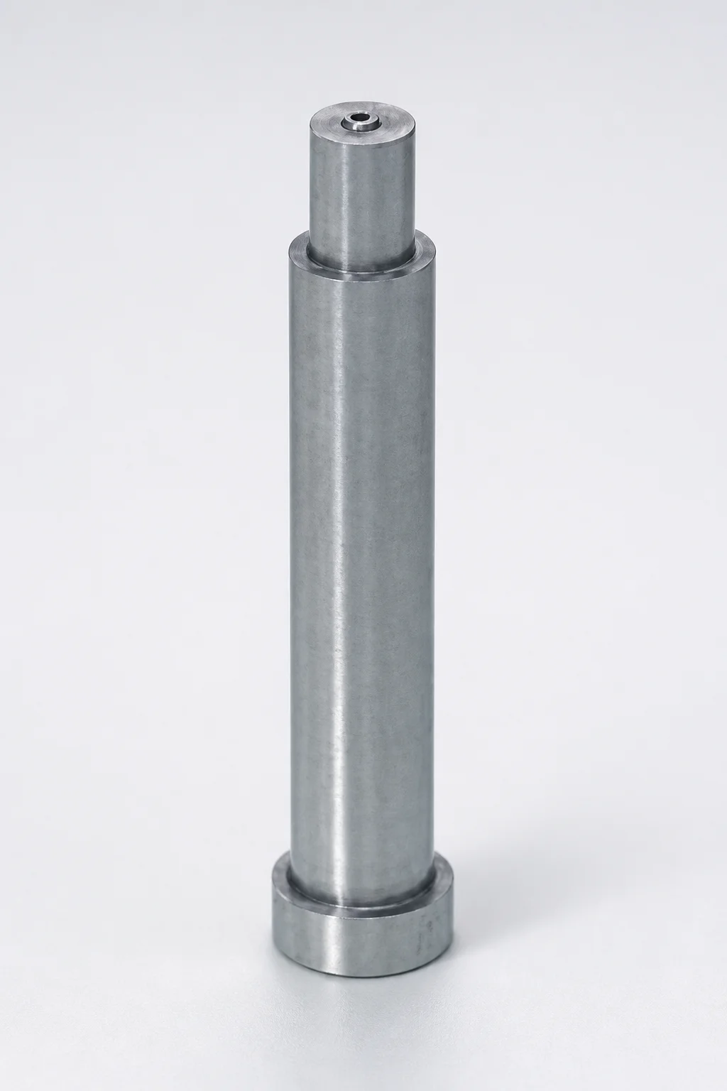
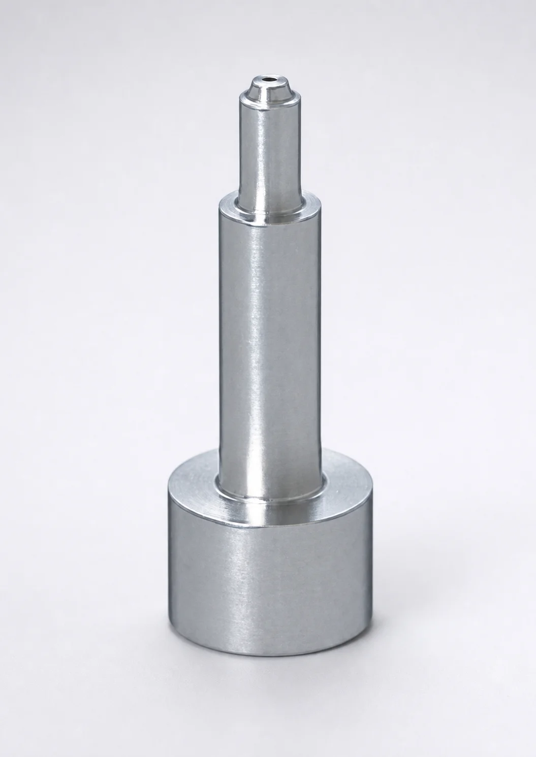
SKH51 Steel Pin-Point Gate Bushings with Head - Round Gate Transition (SR)
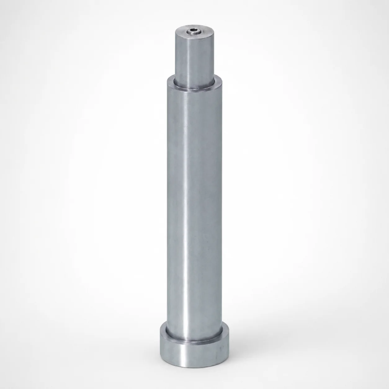
SKH51 Steel Pin-Point Gate Bushings with Head
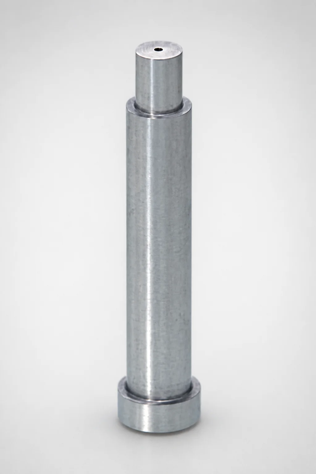
JIS Standard SKH51 Steel Pin-Point Gate Bushings (PGHTBL) with Head
SKH51 Steel Pin-Point Gate Bushings with Head - Round Gate Transition
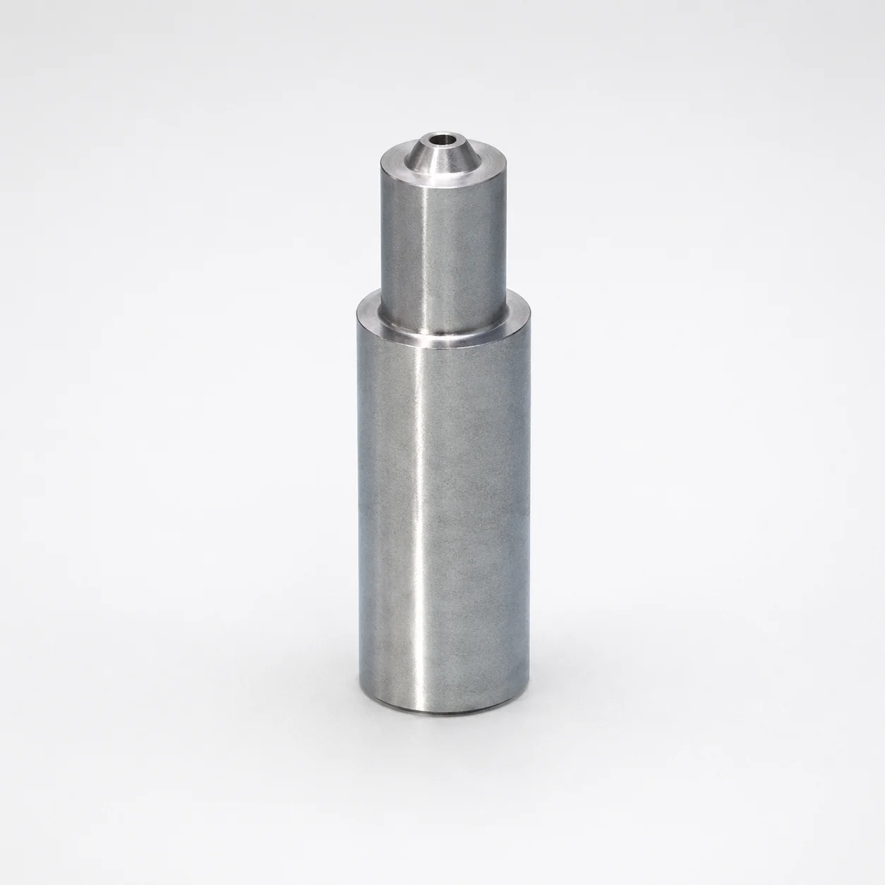
SKH51 Steel Pin-Point Gate Bushings Round Gate Transition SR
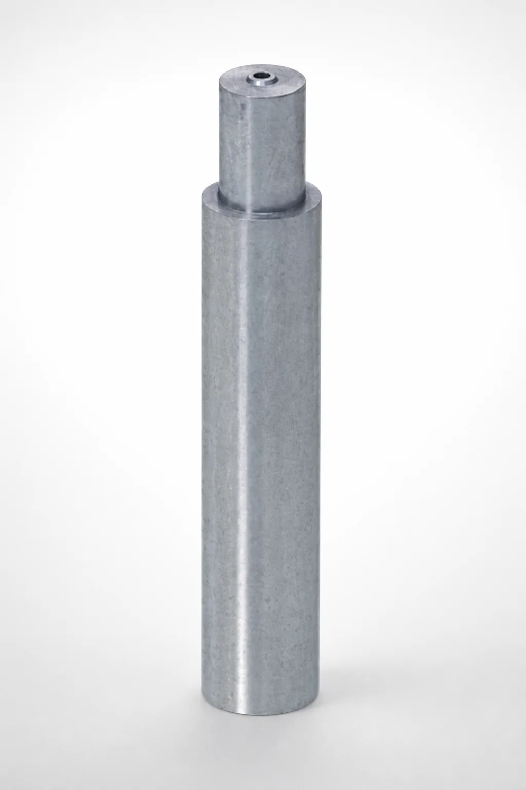
SKH51 Steel Pin-Point Gate Bushings Angle Gate Transition
Need Custom Specifications?
Our engineering team can help with custom configurations, material selection, and volume pricing.