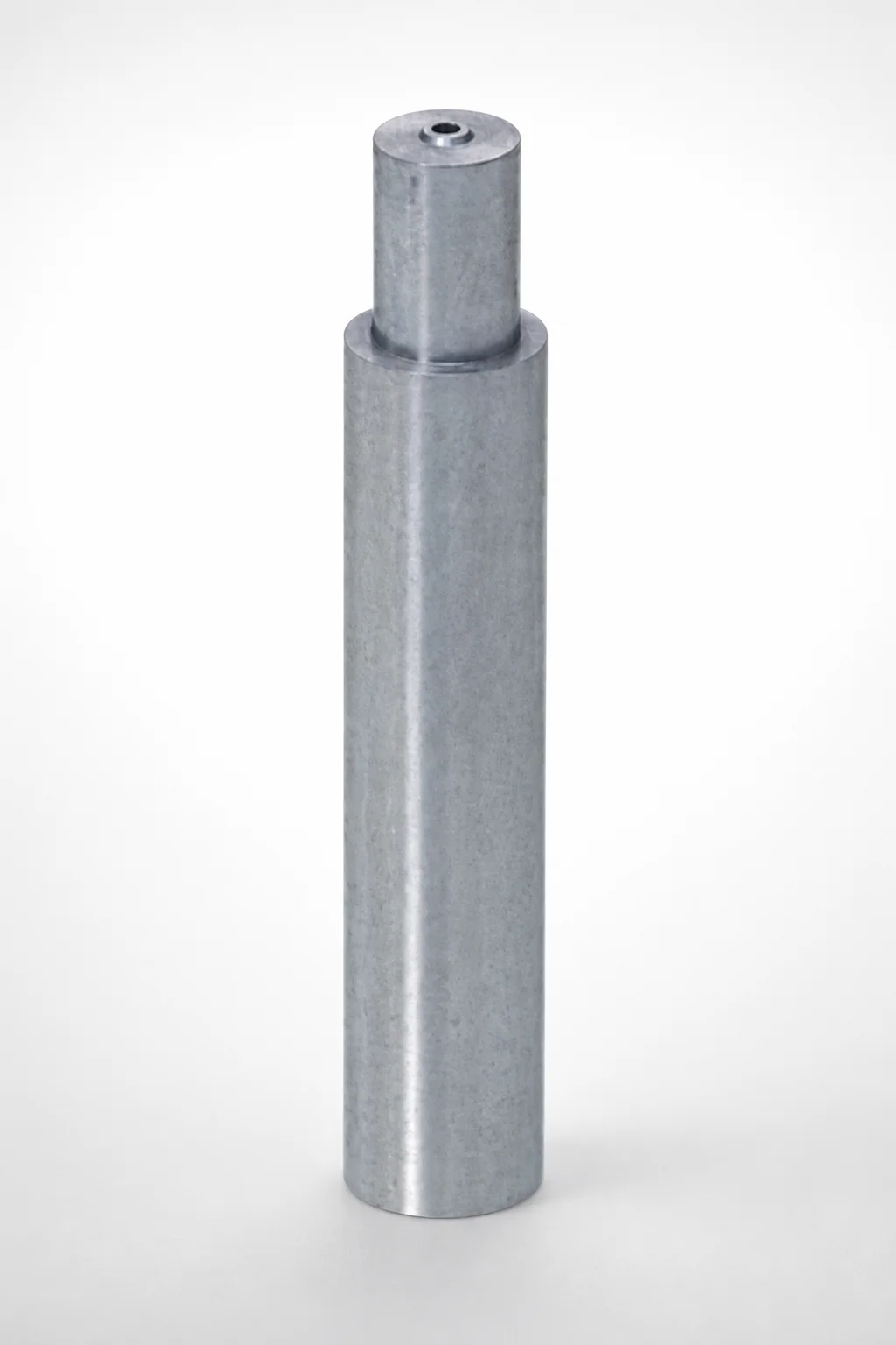
SKH51 Steel Pin-Point Gate Bushings Angle Gate Transition
Pin-Point Gate Bushings (SKH51 steel) with angle gate transition and a tapered tip support stable gate formation and smoother runner flow during injection molding. Designed for repeatable positioning and reliable extraction across production cycles.
- Angle gate transition geometry improves control of gate entry and flow.
- SKH51 hardened steel construction delivers wear resistance for long service life.
- Precision fit using P dimension tolerance (±0.01) supports consistent assembly alignment.
- Widely used in injection mold gate bushings where pinpoint gate formation is critical.
Specifications
64 configurations available
| Tip Type | Tip Shape | P Dimension Tolerance | Tip Straight Tolerance | D (Outer diameter) (mm) | A (Taper angle) (°) | C (Tip length) (mm) | K (Cutting angle) (°) | L (L dimension) (mm) | P (Tip diameter) (mm) | R (Tip R) (mm) | S (Tip angle) (°) | V (Tip diameter) (mm) | type |
|---|---|---|---|---|---|---|---|---|---|---|---|---|---|
| Normal | 1A | ±0.01 | 0 to 0.2 | 2.5 | 1 ~ 3 | 0.2 ~ 0.5 | 20 ~ 30 | 8 ~ 25 | 0.3 ~ 0.6 | - | - | 1.5 ~ 2.4 | - |
| Normal | 1A | ±0.01 | 0 to 0.2 | 3 | 1 ~ 3 | 0.3 ~ 0.8 | 20 ~ 40 | 10 ~ 40 | 0.5 ~ 0.8 | - | - | 2 ~ 2.9 | - |
| Normal | 1A | ±0.01 | 0 to 0.2 | 4 | 1 ~ 3 | 0.3 ~ 0.8 | 20 ~ 40 | 10 ~ 40 | 0.6 ~ 1.2 | - | - | 2.5 ~ 3.9 | - |
| Normal | 1A | ±0.01 | 0 to 0.2 | 5 | 1 ~ 3 | 0.5 ~ 1.5 | 20 ~ 60 | 15 ~ 60 | 0.8 ~ 1.1 | - | - | 3.5 ~ 4.9 | - |
| Normal | 1A | ±0.01 | 0 to 0.2 | 5 | 1 ~ 3 | 0.5 ~ 1.5 | 20 ~ 60 | 15 ~ 60 | 1.2 ~ 1.4 | - | - | 3.5 ~ 4.9 | - |
| Normal | 1A | ±0.01 | 0 to 0.2 | 6 | 1 ~ 3 | 0.5 ~ 1.5 | 20 ~ 60 | 15 ~ 60 | 1 ~ 1.6 | - | - | 4 ~ 5.9 | - |
| Normal | 1A | ±0.01 | 0 to 0.2 | 8 | 1 ~ 3 | 0.5 ~ 1.5 | 20 ~ 60 | 15 ~ 60 | 1.2 ~ 1.6 | - | - | 4.5 ~ 7.9 | - |
| Normal | 1A | ±0.01 | 0 to 0.2 | 10 | 1 ~ 3 | 0.5 ~ 1.5 | 20 ~ 60 | 15 ~ 60 | 1.2 ~ 1.6 | - | - | 5 ~ 9.9 | - |
| Normal | 2A | ±0.01 | 0 to 0.2 | 2.5 | 1 ~ 3 | - | 20 ~ 30 | 8 ~ 25 | 0.3 ~ 0.6 | - | - | - | - |
| Normal | 2A | ±0.01 | 0 to 0.2 | 3 | 1 ~ 3 | - | 20 ~ 40 | 10 ~ 40 | 0.5 ~ 0.8 | - | - | - | - |
| Normal | 2A | ±0.01 | 0 to 0.2 | 4 | 1 ~ 3 | - | 20 ~ 40 | 10 ~ 40 | 0.6 ~ 1.2 | - | - | - | - |
| Normal | 2A | ±0.01 | 0 to 0.2 | 5 | 1 ~ 3 | - | 20 ~ 60 | 15 ~ 60 | 0.8 ~ 1.1 | - | - | - | - |
| Normal | 2A | ±0.01 | 0 to 0.2 | 5 | 1 ~ 3 | - | 20 ~ 60 | 15 ~ 60 | 1.2 ~ 1.4 | - | - | - | - |
| Normal | 2A | ±0.01 | 0 to 0.2 | 6 | 1 ~ 3 | - | 20 ~ 60 | 15 ~ 60 | 1 ~ 1.6 | - | - | - | - |
| Normal | 2A | ±0.01 | 0 to 0.2 | 8 | 1 ~ 3 | - | 20 ~ 60 | 15 ~ 60 | 1.2 ~ 1.6 | - | - | - | - |
| Normal | 2A | ±0.01 | 0 to 0.2 | 10 | 1 ~ 3 | - | 20 ~ 60 | 15 ~ 60 | 1.2 ~ 1.6 | - | - | - | - |
| Normal | 3A | ±0.01 | 0 to 0.2 | 2.5 | 1 ~ 3 | 0.2 ~ 0.5 | 20 ~ 30 | 8 ~ 25 | 0.3 ~ 0.6 | - | 1 ~ 45 | - | - |
| Normal | 3A | ±0.01 | 0 to 0.2 | 3 | 1 ~ 3 | 0.3 ~ 0.8 | 20 ~ 40 | 10 ~ 40 | 0.5 ~ 0.8 | - | 1 ~ 45 | - | - |
| Normal | 3A | ±0.01 | 0 to 0.2 | 4 | 1 ~ 3 | 0.3 ~ 0.8 | 20 ~ 40 | 10 ~ 40 | 0.6 ~ 1.2 | - | 1 ~ 45 | - | - |
| Normal | 3A | ±0.01 | 0 to 0.2 | 5 | 1 ~ 3 | 0.5 ~ 1.5 | 20 ~ 60 | 15 ~ 60 | 0.8 ~ 1.1 | - | 1 ~ 45 | - | - |
| Normal | 3A | ±0.01 | 0 to 0.2 | 5 | 1 ~ 3 | 0.5 ~ 1.5 | 20 ~ 60 | 15 ~ 60 | 1.2 ~ 1.4 | - | 1 ~ 45 | - | - |
| Normal | 3A | ±0.01 | 0 to 0.2 | 6 | 1 ~ 3 | 0.5 ~ 1.5 | 20 ~ 60 | 15 ~ 60 | 1 ~ 1.6 | - | 1 ~ 50 | - | - |
| Normal | 3A | ±0.01 | 0 to 0.2 | 8 | 1 ~ 3 | 0.5 ~ 1.5 | 20 ~ 60 | 15 ~ 60 | 1.2 ~ 1.6 | - | 1 ~ 60 | - | - |
| Normal | 3A | ±0.01 | 0 to 0.2 | 10 | 1 ~ 3 | 0.5 ~ 1.5 | 20 ~ 60 | 15 ~ 60 | 1.2 ~ 1.6 | - | 1 ~ 60 | - | - |
| Normal | 4A | ±0.01 | 0 to 0.2 | 2.5 | 1 ~ 3 | 0.2 ~ 0.5 | 20 ~ 30 | 8 ~ 25 | 0.3 ~ 0.6 | 0.6 ~ 1 | - | - | - |
| Normal | 4A | ±0.01 | 0 to 0.2 | 3 | 1 ~ 3 | 0.3 ~ 0.8 | 20 ~ 40 | 10 ~ 40 | 0.5 ~ 0.8 | 0.8 ~ 1.5 | - | - | - |
| Normal | 4A | ±0.01 | 0 to 0.2 | 4 | 1 ~ 3 | 0.3 ~ 0.8 | 20 ~ 40 | 10 ~ 40 | 0.6 ~ 1.2 | 0.8 ~ 1.5 | - | - | - |
| Normal | 4A | ±0.01 | 0 to 0.2 | 5 | 1 ~ 3 | 0.5 ~ 1.5 | 20 ~ 60 | 15 ~ 60 | 0.8 ~ 1.1 | 1 ~ 2 | - | - | - |
| Normal | 4A | ±0.01 | 0 to 0.2 | 5 | 1 ~ 3 | 0.5 ~ 1.5 | 20 ~ 60 | 15 ~ 60 | 1.2 ~ 1.4 | 1 ~ 2 | - | - | - |
| Normal | 4A | ±0.01 | 0 to 0.2 | 6 | 1 ~ 3 | 0.5 ~ 1.5 | 20 ~ 60 | 15 ~ 60 | 1 ~ 1.6 | 1.5 ~ 3 | - | - | - |
| Normal | 4A | ±0.01 | 0 to 0.2 | 8 | 1 ~ 3 | 0.5 ~ 1.5 | 20 ~ 60 | 15 ~ 60 | 1.2 ~ 1.6 | 2 ~ 4 | - | - | - |
| Normal | 4A | ±0.01 | 0 to 0.2 | 10 | 1 ~ 3 | 0.5 ~ 1.5 | 20 ~ 60 | 15 ~ 60 | 1.2 ~ 1.6 | 2.5 ~ 5 | - | - | - |
| Normal | 5A | ±0.01 | 0 to 0.2 | 2.5 | 1 ~ 3 | 0.2 ~ 0.5 | 20 ~ 30 | 8 ~ 25 | 0.3 ~ 0.6 | - | - | - | - |
| Normal | 5A | ±0.01 | 0 to 0.2 | 3 | 1 ~ 3 | 0.3 ~ 0.8 | 20 ~ 40 | 10 ~ 40 | 0.5 ~ 0.8 | - | - | - | - |
| Normal | 5A | ±0.01 | 0 to 0.2 | 4 | 1 ~ 3 | 0.3 ~ 0.8 | 20 ~ 40 | 10 ~ 40 | 0.6 ~ 1.2 | - | - | - | - |
| Normal | 5A | ±0.01 | 0 to 0.2 | 5 | 1 ~ 3 | 0.5 ~ 1.5 | 20 ~ 60 | 15 ~ 60 | 0.8 ~ 1.1 | - | - | - | - |
| Normal | 5A | ±0.01 | 0 to 0.2 | 5 | 1 ~ 3 | 0.5 ~ 1.5 | 20 ~ 60 | 15 ~ 60 | 1.2 ~ 1.4 | - | - | - | - |
| Normal | 5A | ±0.01 | 0 to 0.2 | 6 | 1 ~ 3 | 0.5 ~ 1.5 | 20 ~ 60 | 15 ~ 60 | 1 ~ 1.6 | - | - | - | - |
| Normal | 5A | ±0.01 | 0 to 0.2 | 8 | 1 ~ 3 | 0.5 ~ 1.5 | 20 ~ 60 | 15 ~ 60 | 1.2 ~ 1.6 | - | - | - | - |
| Normal | 5A | ±0.01 | 0 to 0.2 | 10 | 1 ~ 3 | 0.5 ~ 1.5 | 20 ~ 60 | 15 ~ 60 | 1.2 ~ 1.6 | - | - | - | - |
| Acute angle | 1A | - | 0 to 0.05 | 2.5 | 1 ~ 3 | 0.2 ~ 0.5 | 20 ~ 30 | 8 ~ 25 | 0.3 ~ 0.6 | - | - | 1.5 ~ 2.4 | - |
| Acute angle | 1A | - | 0 to 0.05 | 3 | 1 ~ 3 | 0.3 ~ 0.8 | 20 ~ 40 | 10 ~ 40 | 0.5 ~ 0.8 | - | - | 2 ~ 2.9 | - |
| Acute angle | 1A | - | 0 to 0.05 | 4 | 1 ~ 3 | 0.3 ~ 0.8 | 20 ~ 40 | 10 ~ 40 | 0.6 ~ 1.2 | - | - | 2.5 ~ 3.9 | - |
| Acute angle | 1A | - | 0 to 0.05 | 5 | 1 ~ 3 | 0.5 ~ 1.5 | 20 ~ 60 | 15 ~ 60 | 0.8 ~ 1.1 | - | - | 3.5 ~ 4.9 | - |
| Acute angle | 1A | - | 0 to 0.05 | 5 | 1 ~ 3 | 0.5 ~ 1.5 | 20 ~ 60 | 15 ~ 60 | 1.2 ~ 1.5 | - | - | 3.5 ~ 4.9 | - |
| Acute angle | 1A | - | 0 to 0.05 | 6 | 1 ~ 3 | 0.5 ~ 1.5 | 20 ~ 60 | 15 ~ 60 | 1 ~ 1.6 | - | - | 4 ~ 5.9 | - |
| Acute angle | 1A | - | 0 to 0.05 | 8 | 1 ~ 3 | 0.5 ~ 1.5 | 20 ~ 60 | 15 ~ 60 | 1.2 ~ 1.6 | - | - | 4.5 ~ 7.9 | - |
| Acute angle | 1A | - | 0 to 0.05 | 10 | 1 ~ 3 | 0.5 ~ 1.5 | 20 ~ 60 | 15 ~ 60 | 1.2 ~ 1.6 | - | - | 5 ~ 9.9 | - |
| Acute angle | 2A | - | 0 to 0.05 | 2.5 | 1 ~ 3 | - | 20 ~ 30 | 8 ~ 25 | 0.3 ~ 0.6 | - | - | - | - |
| Acute angle | 2A | - | 0 to 0.05 | 3 | 1 ~ 3 | - | 20 ~ 40 | 10 ~ 40 | 0.5 ~ 0.8 | - | - | - | - |
Product Guide
Application Scenarios+
These SKH51 pin-point gate bushings are used in injection mold tooling to form precise, repeatable runner-to-cavity gate features. The angle gate transition and tapered tip help stabilize gate entry geometry and promote smoother runner flow, which reduces gate defects tied to inconsistent gate formation.
- Automotive and appliance connector molds: Ideal for pinpoint gating where small gate size and controlled flow are needed to limit cosmetic impact and maintain dimensional consistency across production cycles.
- Electronics housings with delicate appearance surfaces: The tapered tip and selectable tip types/shapes support consistent gate vestige formation, improving surface quality after ejection.
- Industrial fluid/thermoplastic components: The hardened SKH51 construction supports long service intervals in high-cycle molds where bushings experience wear from repeated pin-point gating and extraction.
The SKH51 variant is suited to these applications because it offers strong wear resistance while maintaining the sharp geometry necessary for controlled gate formation.
Material & Process Details+
SKH51 is a high-speed steel commonly regarded as comparable to the AISI M2 family, selected for tooling surfaces that need high wear resistance. In pin-gate bushing service, the hardness supports resistance to abrasion at the tapered tip where flow and gate formation contact occur repeatedly.
- Heat treatment state: Typically supplied hardened (quenched and tempered) to reach stable operating hardness for production molds.
- Hardness & performance trade-offs: Higher hardness improves wear resistance and tip durability, but excessive hardness can reduce toughness; proper tempering balances crack resistance during mold shutdown/handling and thermal cycling.
- Wear vs. toughness: Compared with lower-alloy steels, SKH51 prioritizes wear resistance; compared with ultra-fine carbide wear grades, it generally offers a more favorable combination of hardness stability and toughness.
The hardened condition is critical for maintaining tip geometry (tip diameter/angle) over repeated extraction cycles.
Sizing & Selection Guide+
Selection starts by matching the bushing exterior and gate tip dimensions to the mold’s sprue/runner gate system. Use D (outer diameter) = 2.5 ~ 10 mm to fit the available bushing pocket, and confirm that your mold insert bore can accommodate the intended fit.
- Tip diameter and gate opening control: Choose P (tip diameter) = 0.3 ~ 1.2 mm and the V (tip diameter) = 1.5 ~ 5 mm (if applicable to the selected shape) to achieve the required pinpoint gate size and flow restriction.
- Geometry tuning: Select A (taper angle) = 1 ~ 3°, C (tip length) = 0.2 ~ 0.5 / 0.3 ~ 0.8 / 0.5 ~ 1.5 mm, and R (tip radius) = 0.6 ~ 5 mm based on how aggressive you want the transition from runner to gate to be.
- Dimensional tolerance: The P dimension tolerance is ±0.01, supporting consistent assembly alignment of the tip diameter across production.
Finally, choose the mold-side features to maintain consistent clearance during assembly; use the fixed ±0.01 P tolerance when validating gate opening targets.
Frequently Asked Questions
Which dimension range controls the pinpoint gate opening on SKH51 angle-transition gate bushings?+
The pinpoint gate opening is primarily controlled by P (tip diameter) = 0.3 ~ 1.2 mm. This dimension has a specified P tolerance of ±0.01, supporting stable gate formation from assembly to assembly.
How do I choose between normal and acute-angle tip types for a pinpoint gate transition?+
The selected Tip Type (Normal vs. Acute angle) changes the effective gate transition behavior at the tapered tip. Pair the tip type with the available K (cutting angle) = 20~30 / 20~40 / 20~60° and S (tip angle) = 1~45 / 1~50 / 1~60° ranges to match your required runner-to-gate flow control.
What taper angle options are available for the angle gate transition geometry?+
The taper angle is fixed at A (taper angle) = 1 ~ 3°. Use this together with C (tip length) to tune how quickly the flow transitions from the runner into the gate region.
How should I match the bushing outer diameter to my mold sprue/runner bushing pocket?+
Select D (outer diameter) = 2.5 ~ 10 mm to correspond to the bushing pocket bore size. Confirm assembly clearances in your mold design and account for the specified fit behavior at the P dimension tolerance (±0.01) level, since tip diameter accuracy influences the final gate opening.
What tip radius and length ranges are most relevant for maintaining gate consistency over long runs?+
Choose R (tip R) = 0.6 ~ 5 mm and C (tip length) = 0.2~0.5 / 0.3~0.8 / 0.5~1.5 mm to define the local transition profile that forms the gate consistently. The hardened SKH51 construction is intended to resist wear at this geometry, helping maintain performance across repeated injection and extraction cycles.
Related Products
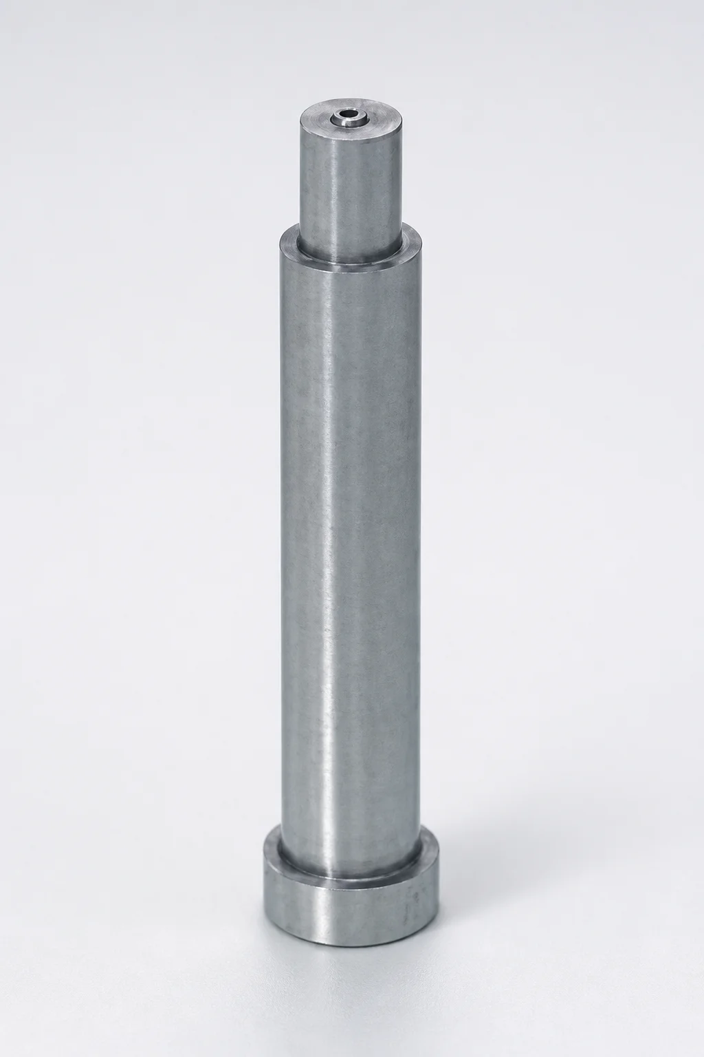
SKH51 Steel Pin-Point Gate Bushings with Head - Round Gate Transition (SR)
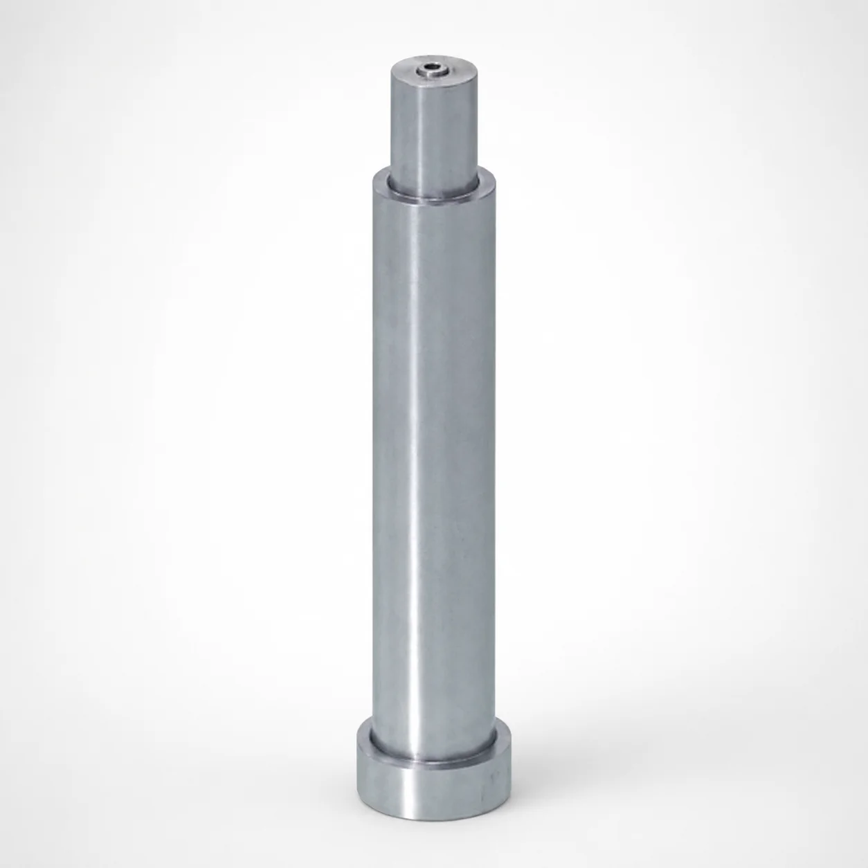
SKH51 Steel Pin-Point Gate Bushings with Head
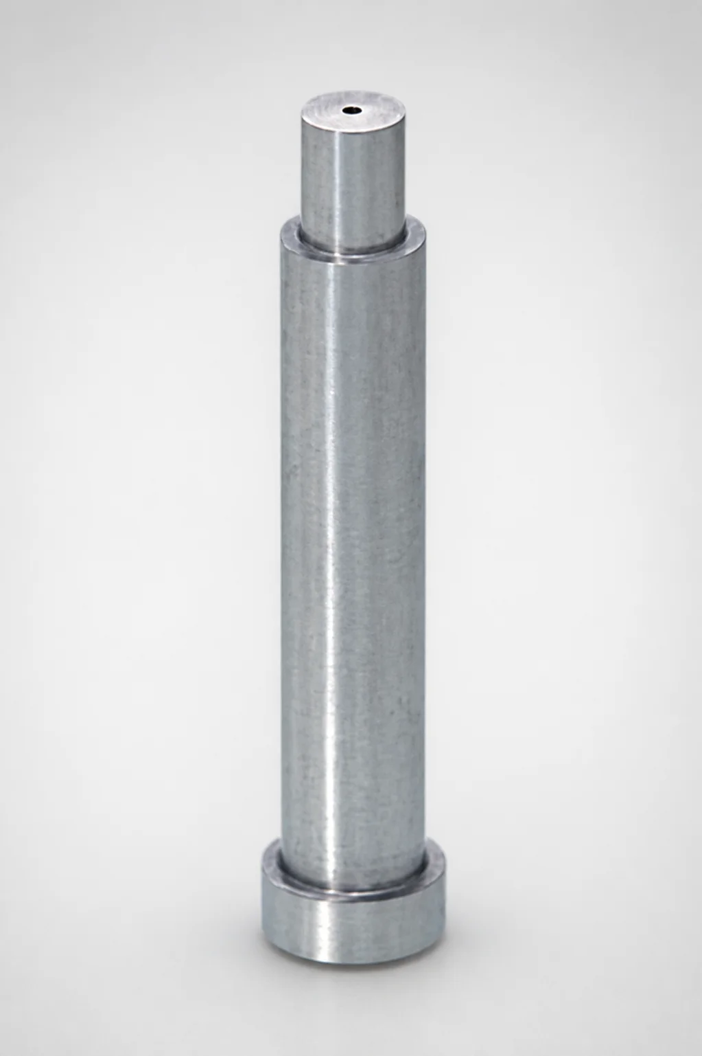
JIS Standard SKH51 Steel Pin-Point Gate Bushings (PGHTBL) with Head
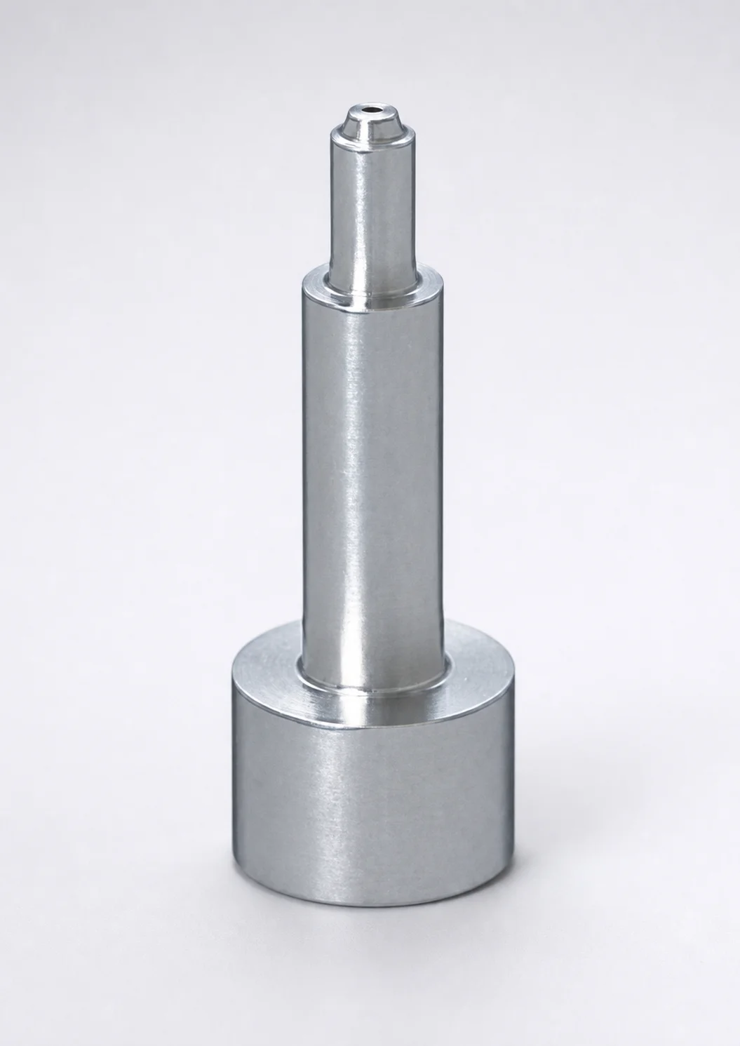
SKH51 Steel Pin-Point Gate Bushings with Head - Round Gate Transition
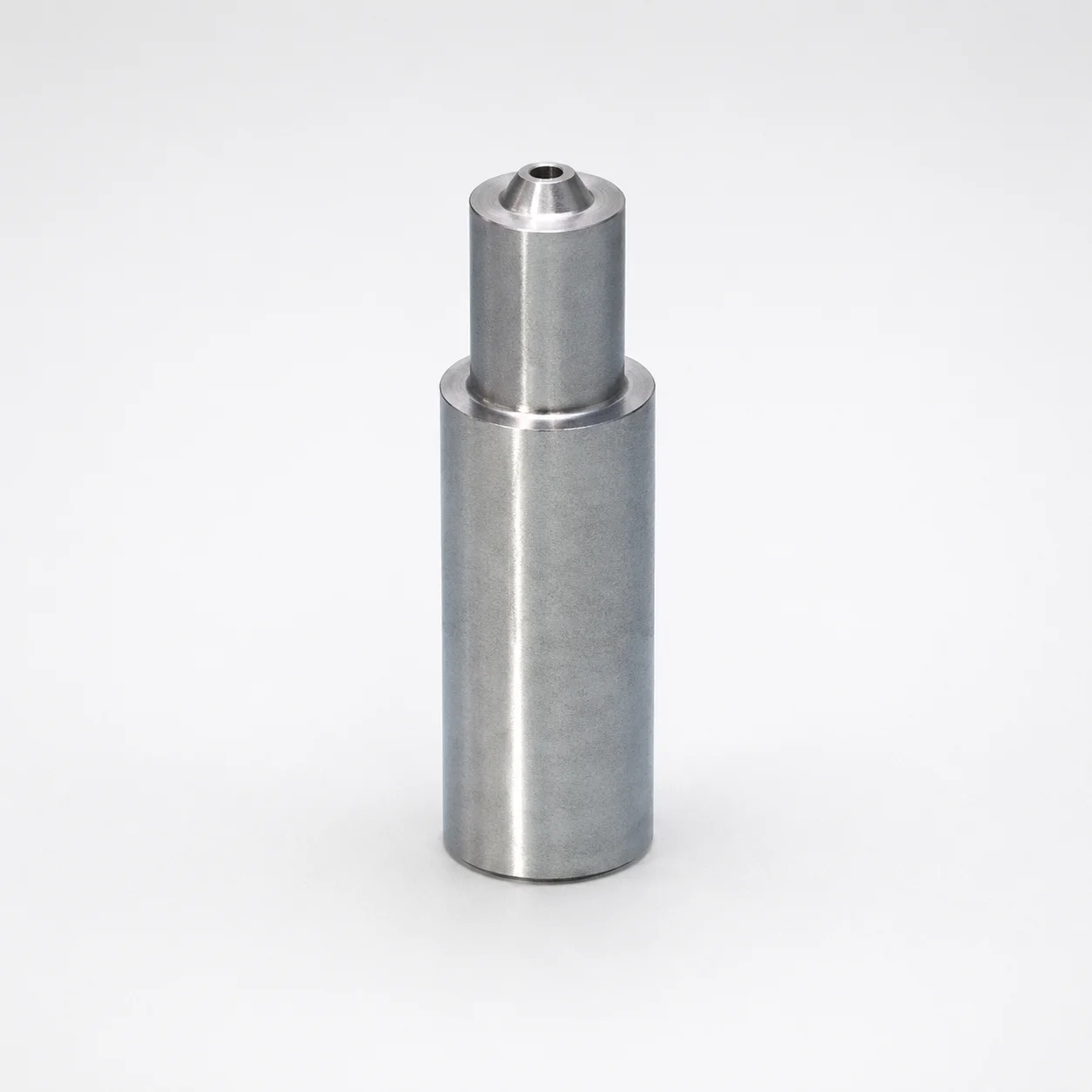
SKH51 Steel Pin-Point Gate Bushings Round Gate Transition SR
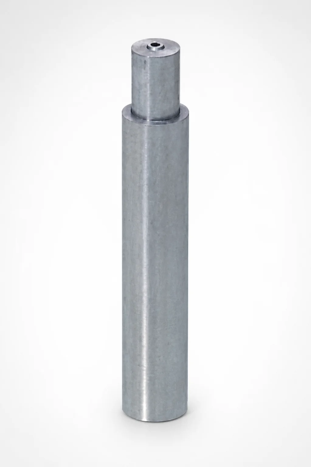
JIS Standard SKH51 Steel Pin-Point Gate Bushings Round Gate Transition SR
Need Custom Specifications?
Our engineering team can help with custom configurations, material selection, and volume pricing.