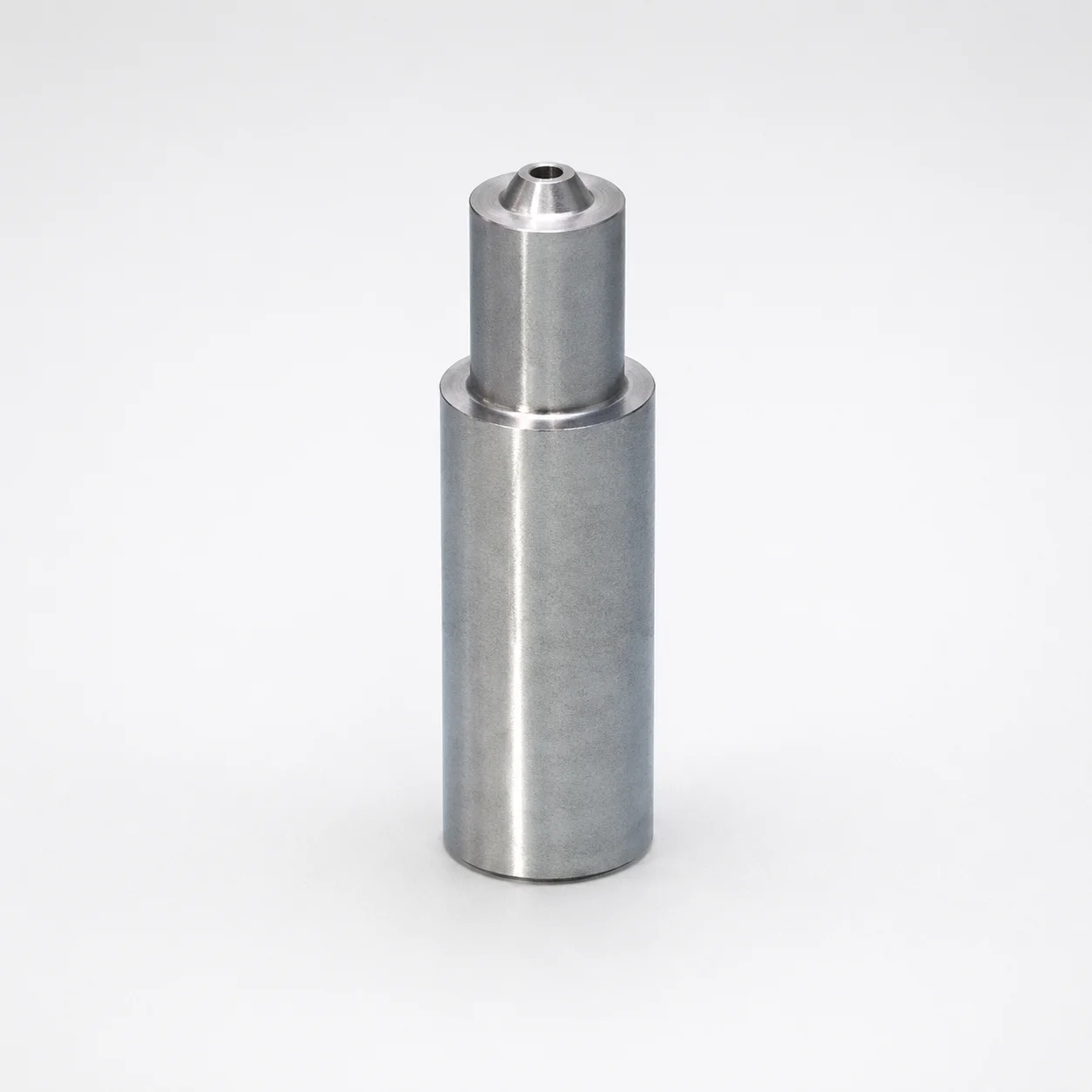
SKH51 Steel Pin-Point Gate Bushings Round Gate Transition SR
Pin-Point Gate Bushings (SKH51 steel) with a Round Gate Transition and SR tip step provide consistent pinpoint gating alignment in injection molds. The small-shank design supports stable positioning for repeatable gate formation.
- Round gate transition supports smooth material flow from runner to gate
- SR tip step shape improves pinpoint gate repeatability and part contact control
- SKH51 steel with quench-hardening construction delivers strong wear resistance
- Designed for tight assembly using D tolerance (0 to -0.005 mm) references
Specifications
6 configurations available
| P Dimension Tolerance | D (Outer diameter) (mm) | A (Secondary sprue angle) (°) | C (Tip length) (mm) | L (L dimension) (mm) | P (Tip diameter) (mm) | type |
|---|---|---|---|---|---|---|
| ±0.01 | 1.5 | 2 | 0 ~ 0.5 | 6 ~ 20 | 0.3 | - |
| ±0.01 | 1.6 | 2 | 0 ~ 0.5 | 6 ~ 20 | 0.3 ~ 0.4 | - |
| ±0.01 | 1.8 | 2 | 0 ~ 0.5 | 6 ~ 20 | 0.3 ~ 0.5 | - |
| ±0.005 | 1.5 | 2 | 0 ~ 0.5 | 6 ~ 20 | 0.3 | - |
| ±0.005 | 1.6 | 2 | 0 ~ 0.5 | 6 ~ 20 | 0.3 ~ 0.4 | - |
| ±0.005 | 1.8 | 2 | 0 ~ 0.5 | 6 ~ 20 | 0.3 ~ 0.5 | - |
Product Guide
Application Scenarios+
Pinpoint gate bushings are used to control where polymer first enters the cavity, making them ideal for precision parting lines and small-gate geometries. This steel variant, featuring a round gate transition and an SR tip step, helps maintain consistent gate formation by stabilizing the runner-to-gate flow and the final gate contact area.
- Automotive connector and sensor housings: For small, centrally fed gates, the round transition supports smooth flow from sprue/runner to the pinpoint gate while the SR step promotes repeatable gate size and location across production cycles.
- Medical device housings and caps: Reliable pinpoint gating reduces variation in weld line/jetting behavior and supports repeatability for tight cosmetic and dimensional requirements.
- Electronics enclosures with fine gating: The small-shank positioning supports stable mold locating, helping achieve uniform gating from shot to shot in high-volume molding.
The SKH51 steel construction is suited for these use cases where wear at the gate tip and consistent locating are critical to long-run production stability.
Material & Process Details+
The bushing is made from SKH51 steel, a quench-hardening high-speed/tool steel grade commonly selected for components that require wear resistance at high-contact points. In this type of quenching-and-tempering processing, the material is typically supplied in a hardened condition to balance hardness and toughness.
- Wear resistance: Higher hardness improves resistance to tip wear and erosion during repeated pinpoint gating.
- Toughness trade-off: As hardness increases, impact toughness can decrease; proper tempering is important to avoid chipping at the SR tip step.
- Surface durability: Because the bushing tip directly forms the gate, hardened SKH51 helps maintain the gate profile longer than softer steels.
If comparing grades, consider that pre-hardened/low-alloy steels may offer better toughness but typically lower wear life at the pinpoint gate contact region. SKH51 targets longer service where stable gate geometry is required.
Sizing & Selection Guide+
Select the bushing dimensions by matching the sprue/gate transition geometry and the gate land requirements of your cavity design. Start with D (outer diameter)—available as 1.5, 1.6, or 1.8 mm—to ensure the bushing fits the leader bore and maintains proper coaxial alignment with the gate.
- P (tip diameter): Choose from 0.3, 0.3–0.4, or 0.3–0.5 mm depending on the target pinpoint gate thickness/diameter in the parting surface.
- C (tip length): Fixed at 0 to 0.5 mm to control how far the tip projects into the cavity-side gate area.
- L (L dimension): Fixed at 6 to 20 mm to match the mold thickness and runner/sprue length of your tooling layout.
- A (secondary sprue angle): Fixed at 2° for the round transition geometry.
For fit, reference the D tolerance of 0 to -0.005 mm (tight assembly). For P, use the provided tolerance options (±0.01 or ±0.005) to control gate diameter accuracy and repeatability.
Frequently Asked Questions
How do I choose the right tip diameter (P) and tolerance for a specific pinpoint gate size?+
Select P from 0.3, 0.3–0.4, or 0.3–0.5 mm based on the target pinpoint gate diameter in your cavity/gate insert. Use the provided P dimension tolerances (±0.01 or ±0.005) to control gate diameter variation. Tighter tolerance is typically preferred where gate size directly affects flow balance and cosmetic gate vestige.
What is the correct way to match the bushing outer diameter (D) for stable locating in the sprue bushing bore?+
Choose D as 1.5, 1.6, or 1.8 mm to suit your mold’s guide/leader bore and maintain concentricity to the pinpoint gate. Follow the assembly allowance using the stated D tolerance (0 to -0.005 mm). This negative tolerance range helps ensure stable seating without excessive looseness that can shift gate location.
How do C (tip length) and L (overall length) impact gate penetration and mold thickness compatibility?+
C is fixed at 0 to 0.5 mm, which sets the tip projection into the gate land region; use it to control how the SR tip step contacts the cavity-side gate. L is fixed at 6 to 20 mm to match your sprue/runner length and overall mold stack. Confirm both against your mold thickness so the gate formation occurs reliably without over-penetration.
Why are the round gate transition and SR tip step relevant for repeatable pinpoint gating?+
The round gate transition supports smoother flow from runner/sprue into the pinpoint gate area, reducing flow irregularities at the transition. The SR tip step improves pinpoint gate repeatability by defining the final contact geometry at the gate tip. This combination helps maintain a consistent gate profile over many production cycles.
What material characteristics are expected from SKH51, and how does it compare to softer bushing steels for production life?+
This component uses SKH51 steel with a quench-hardening approach, selected for strong wear resistance at the pinpoint gate region. Higher hardness supports longer durability against tip wear and erosion that can change gate size. Compared with softer steels, the trade-off is typically reduced toughness if not properly tempered; however, the hardened/toughened condition is intended to maintain stable gate geometry in production.
Related Products
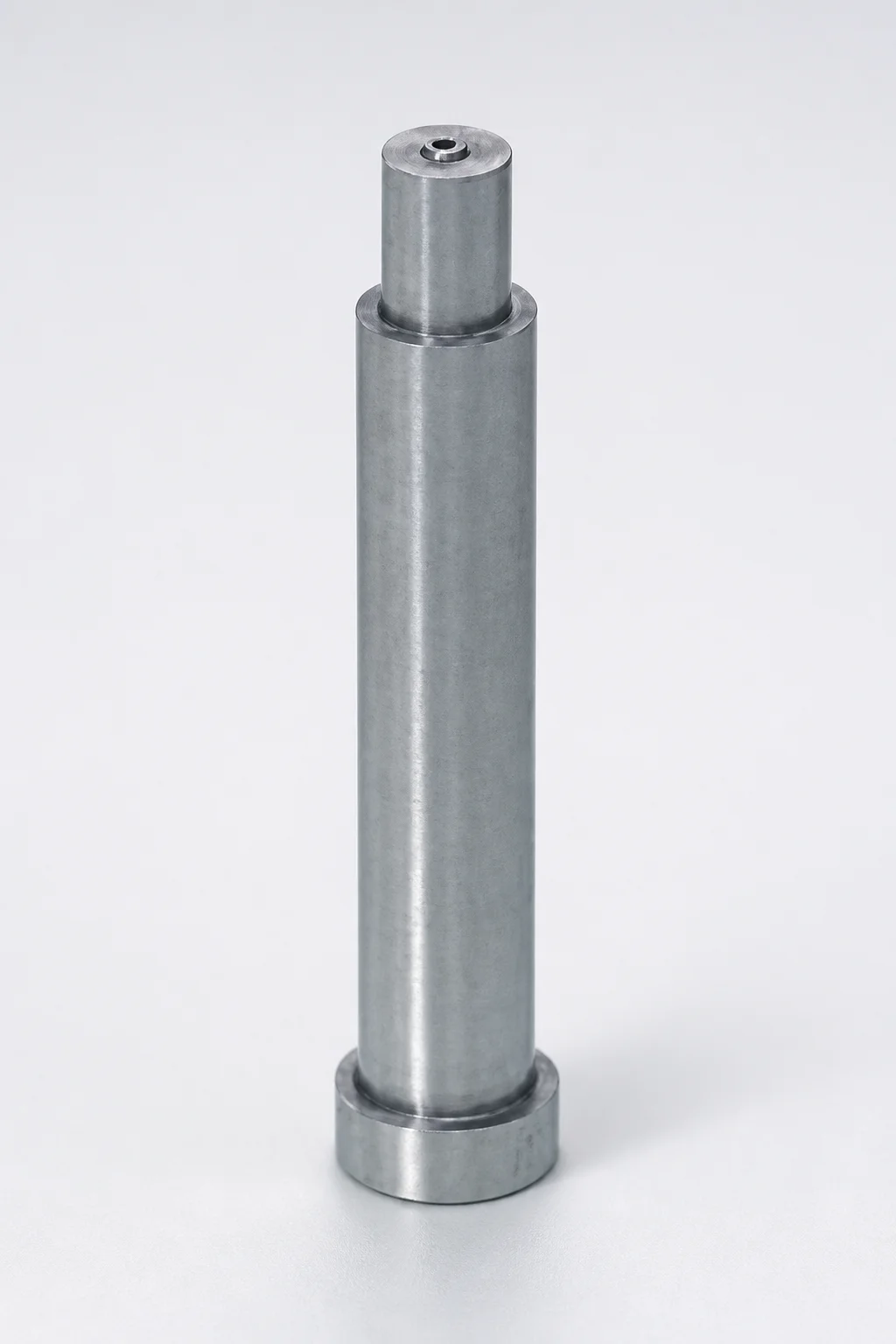
SKH51 Steel Pin-Point Gate Bushings with Head - Round Gate Transition (SR)
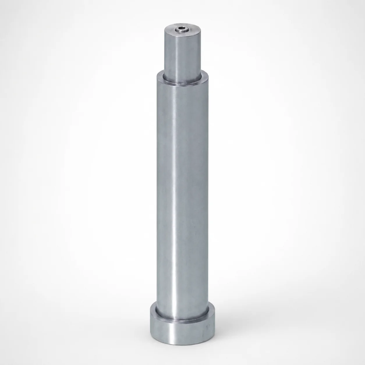
SKH51 Steel Pin-Point Gate Bushings with Head
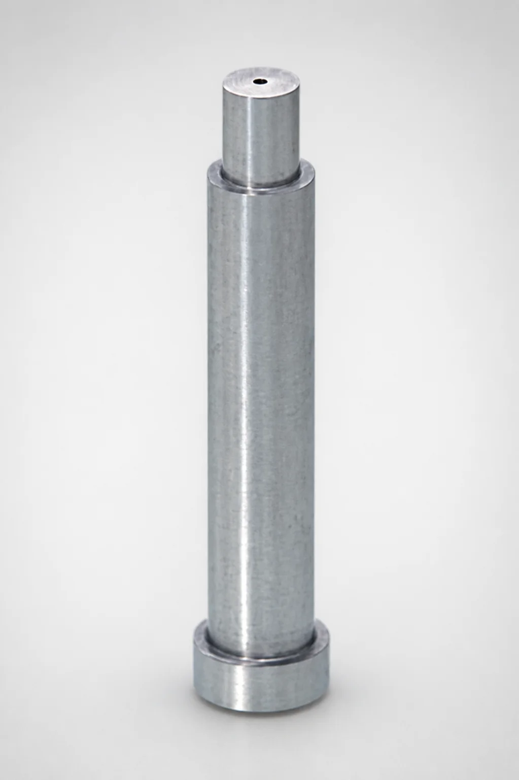
JIS Standard SKH51 Steel Pin-Point Gate Bushings (PGHTBL) with Head
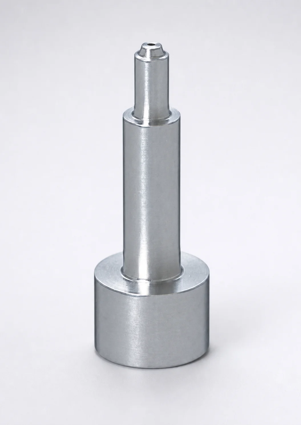
SKH51 Steel Pin-Point Gate Bushings with Head - Round Gate Transition
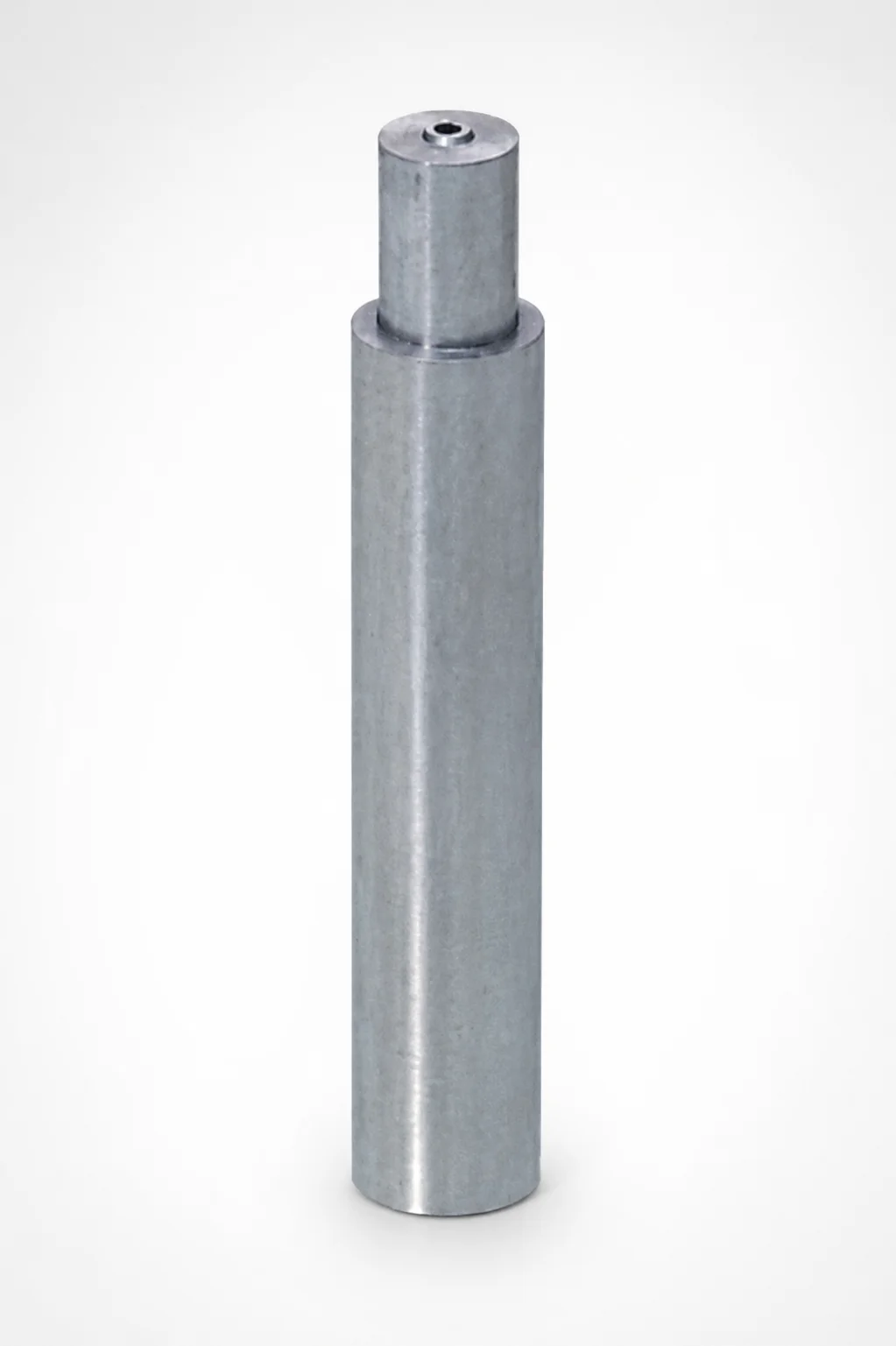
JIS Standard SKH51 Steel Pin-Point Gate Bushings Round Gate Transition SR
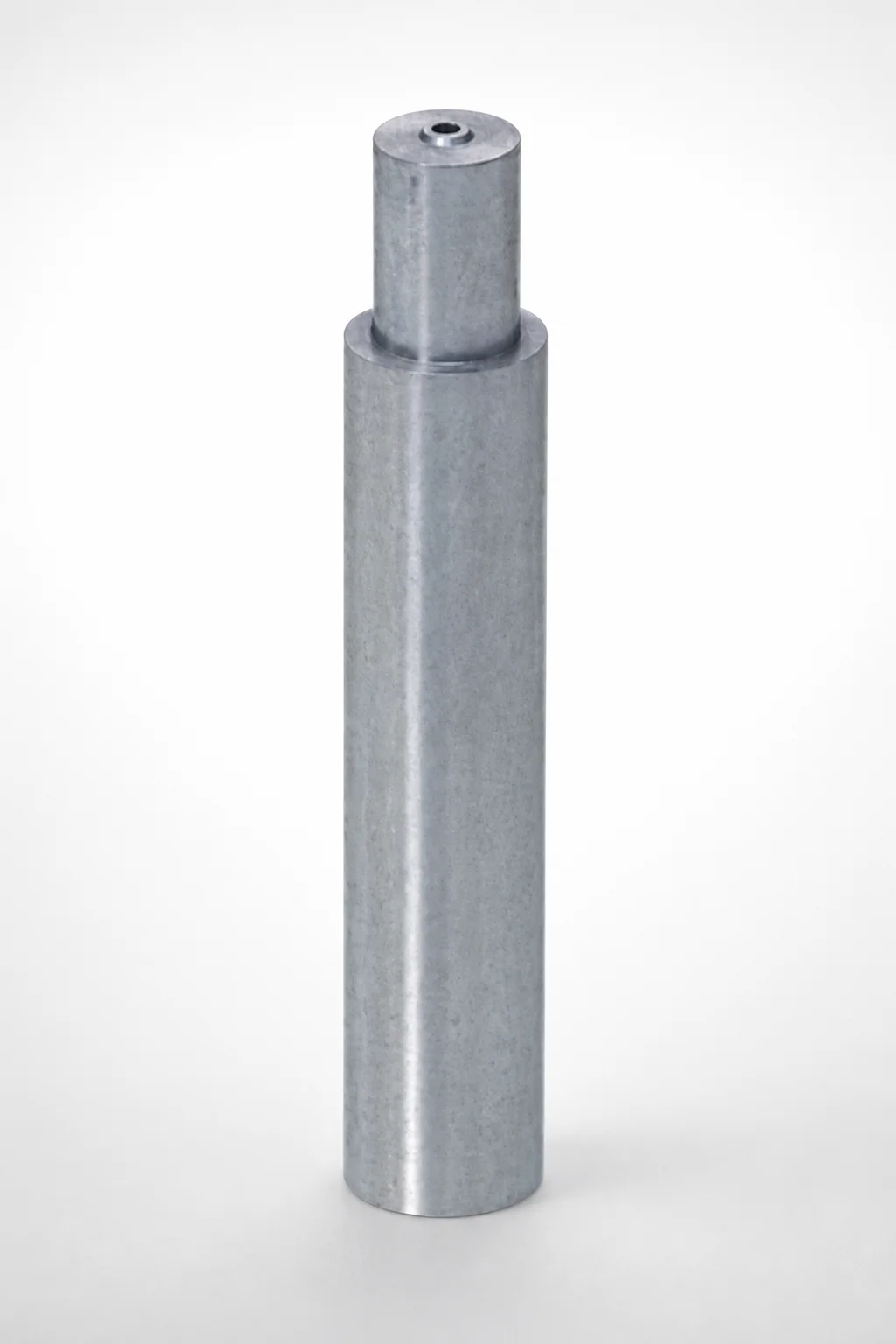
SKH51 Steel Pin-Point Gate Bushings Angle Gate Transition
Need Custom Specifications?
Our engineering team can help with custom configurations, material selection, and volume pricing.