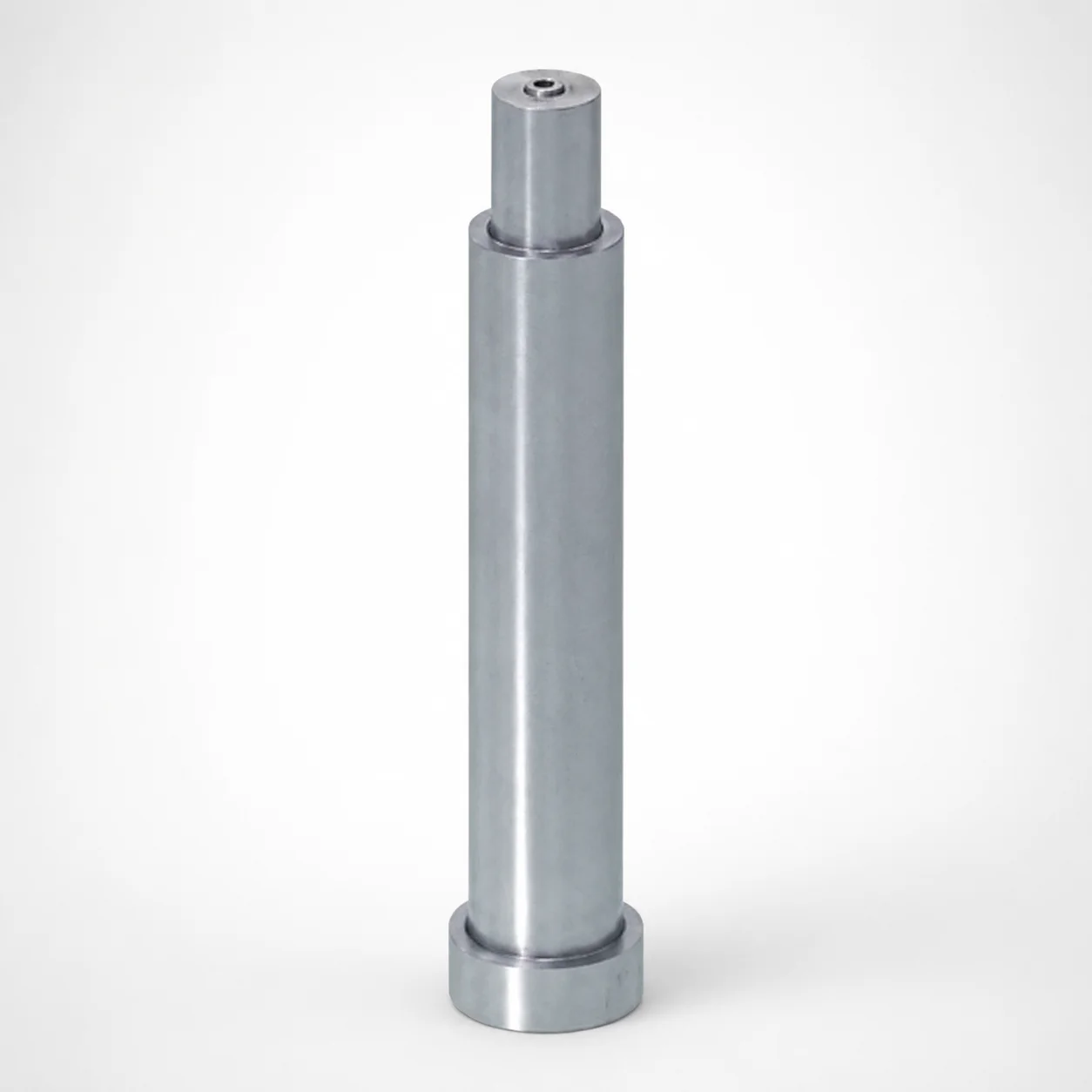
SKH51 Steel Pin-Point Gate Bushings with Head
Pin-Point Gate Bushings with Head (SKH51 steel) are designed for an angle gate transition, using a tapered pilot tip to help form consistent gate openings. The head provides positive positioning for repeatable press performance.
- Tapered tip for controlled pin-point gate formation in angle gate transition applications
- SKH51 steel construction with hardened cutting surfaces for reliable wear resistance
- Precision fit enabled by D dimension tolerance 0/-0.005 for stable assembly alignment
- Suitable for mold makers seeking consistent gate bush performance in production runs
Specifications
40 configurations available
| Tip Shape | D (Outer diameter) (mm) | A (Secondary sprue angle) (°) | C (Tip length) (mm) | K (Cutting angle) (°) | L (L dimension) (mm) | P (Tip diameter) (mm) | R (Tip R) (mm) | S (Tip angle) (°) | V (Tip diameter) (mm) | type |
|---|---|---|---|---|---|---|---|---|---|---|
| 1A | 2.5 | 1 ~ 3 | 0.2 ~ 0.5 | 20 ~ 30 | 10 ~ 25 | 0.3 ~ 0.6 | - | - | 1.5 ~ 2.4 | - |
| 1A | 3 | 1 ~ 3 | 0.3 ~ 0.8 | 20 ~ 40 | 20 ~ 40 | 0.5 ~ 0.8 | - | - | 2 ~ 2.9 | - |
| 1A | 4 | 1 ~ 3 | 0.3 ~ 0.8 | 20 ~ 40 | 20 ~ 40 | 0.6 ~ 1.2 | - | - | 2.5 ~ 3.9 | - |
| 1A | 5 | 1 ~ 3 | 0.5 ~ 1.5 | 20 ~ 60 | 20 ~ 60 | 0.8 ~ 1.1 | - | - | 3.5 ~ 4.9 | - |
| 1A | 5 | 1 ~ 3 | 0.5 ~ 1.5 | 20 ~ 60 | 20 ~ 60 | 1.2 ~ 1.4 | - | - | 3.5 ~ 4.9 | - |
| 1A | 6 | 1 ~ 3 | 0.5 ~ 1.5 | 20 ~ 60 | 20 ~ 60 | 1 ~ 1.6 | - | - | 4 ~ 5.9 | - |
| 1A | 8 | 1 ~ 3 | 0.5 ~ 1.5 | 20 ~ 60 | 20 ~ 60 | 1.2 ~ 1.6 | - | - | 4.5 ~ 7.9 | - |
| 1A | 10 | 1 ~ 3 | 0.5 ~ 1.5 | 20 ~ 60 | 20 ~ 60 | 1.2 ~ 1.6 | - | - | 5 ~ 9.9 | - |
| 2A | 2.5 | 1 ~ 3 | - | 20 ~ 30 | 10 ~ 25 | 0.3 ~ 0.6 | - | - | - | - |
| 2A | 3 | 1 ~ 3 | - | 20 ~ 40 | 20 ~ 40 | 0.5 ~ 0.8 | - | - | - | - |
| 2A | 4 | 1 ~ 3 | - | 20 ~ 40 | 20 ~ 40 | 0.6 ~ 1.2 | - | - | - | - |
| 2A | 5 | 1 ~ 3 | - | 20 ~ 60 | 20 ~ 60 | 0.8 ~ 1.1 | - | - | - | - |
| 2A | 5 | 1 ~ 3 | - | 20 ~ 60 | 20 ~ 60 | 1.2 ~ 1.4 | - | - | - | - |
| 2A | 6 | 1 ~ 3 | - | 20 ~ 60 | 20 ~ 60 | 1 ~ 1.6 | - | - | - | - |
| 2A | 8 | 1 ~ 3 | - | 20 ~ 60 | 20 ~ 60 | 1.2 ~ 1.6 | - | - | - | - |
| 2A | 10 | 1 ~ 3 | - | 20 ~ 60 | 20 ~ 60 | 1.2 ~ 1.6 | - | - | - | - |
| 3A | 2.5 | 1 ~ 3 | 0.2 ~ 0.5 | 20 ~ 30 | 10 ~ 25 | 0.3 ~ 0.6 | - | 1 ~ 45 | - | - |
| 3A | 3 | 1 ~ 3 | 0.3 ~ 0.8 | 20 ~ 40 | 20 ~ 40 | 0.5 ~ 0.8 | - | 1 ~ 45 | - | - |
| 3A | 4 | 1 ~ 3 | 0.3 ~ 0.8 | 20 ~ 40 | 20 ~ 40 | 0.6 ~ 1.2 | - | 1 ~ 45 | - | - |
| 3A | 5 | 1 ~ 3 | 0.5 ~ 1.5 | 20 ~ 60 | 20 ~ 60 | 0.8 ~ 1.1 | - | 1 ~ 45 | - | - |
| 3A | 5 | 1 ~ 3 | 0.5 ~ 1.5 | 20 ~ 60 | 20 ~ 60 | 1.2 ~ 1.4 | - | 1 ~ 45 | - | - |
| 3A | 6 | 1 ~ 3 | 0.5 ~ 1.5 | 20 ~ 60 | 20 ~ 60 | 1 ~ 1.6 | - | 1 ~ 50 | - | - |
| 3A | 8 | 1 ~ 3 | 0.5 ~ 1.5 | 20 ~ 60 | 20 ~ 60 | 1.2 ~ 1.6 | - | 1 ~ 60 | - | - |
| 3A | 10 | 1 ~ 3 | 0.5 ~ 1.5 | 20 ~ 60 | 20 ~ 60 | 1.2 ~ 1.6 | - | 1 ~ 60 | - | - |
| 4A | 2.5 | 1 ~ 3 | 0.2 ~ 0.5 | 20 ~ 30 | 10 ~ 25 | 0.3 ~ 0.6 | 0.6 ~ 1 | - | - | - |
| 4A | 3 | 1 ~ 3 | 0.3 ~ 0.8 | 20 ~ 40 | 20 ~ 40 | 0.5 ~ 0.8 | 0.8 ~ 1.5 | - | - | - |
| 4A | 4 | 1 ~ 3 | 0.3 ~ 0.8 | 20 ~ 40 | 20 ~ 40 | 0.6 ~ 1.2 | 0.8 ~ 1.5 | - | - | - |
| 4A | 5 | 1 ~ 3 | 0.5 ~ 1.5 | 20 ~ 60 | 20 ~ 60 | 0.8 ~ 1.1 | 1 ~ 2 | - | - | - |
| 4A | 5 | 1 ~ 3 | 0.5 ~ 1.5 | 20 ~ 60 | 20 ~ 60 | 1.2 ~ 1.4 | 1 ~ 2 | - | - | - |
| 4A | 6 | 1 ~ 3 | 0.5 ~ 1.5 | 20 ~ 60 | 20 ~ 60 | 1 ~ 1.6 | 1.5 ~ 3 | - | - | - |
| 4A | 8 | 1 ~ 3 | 0.5 ~ 1.5 | 20 ~ 60 | 20 ~ 60 | 1.2 ~ 1.6 | 2 ~ 4 | - | - | - |
| 4A | 10 | 1 ~ 3 | 0.5 ~ 1.5 | 20 ~ 60 | 20 ~ 60 | 1.2 ~ 1.6 | 2.5 ~ 5 | - | - | - |
| 5A | 2.5 | 1 ~ 3 | 0.2 ~ 0.5 | 20 ~ 30 | 10 ~ 25 | 0.3 ~ 0.6 | - | - | - | - |
| 5A | 3 | 1 ~ 3 | 0.3 ~ 0.8 | 20 ~ 40 | 20 ~ 40 | 0.5 ~ 0.8 | - | - | - | - |
| 5A | 4 | 1 ~ 3 | 0.3 ~ 0.8 | 20 ~ 40 | 20 ~ 40 | 0.6 ~ 1.2 | - | - | - | - |
| 5A | 5 | 1 ~ 3 | 0.5 ~ 1.5 | 20 ~ 60 | 20 ~ 60 | 0.8 ~ 1.1 | - | - | - | - |
| 5A | 5 | 1 ~ 3 | 0.5 ~ 1.5 | 20 ~ 60 | 20 ~ 60 | 1.2 ~ 1.4 | - | - | - | - |
| 5A | 6 | 1 ~ 3 | 0.5 ~ 1.5 | 20 ~ 60 | 20 ~ 60 | 1 ~ 1.6 | - | - | - | - |
| 5A | 8 | 1 ~ 3 | 0.5 ~ 1.5 | 20 ~ 60 | 20 ~ 60 | 1.2 ~ 1.6 | - | - | - | - |
| 5A | 10 | 1 ~ 3 | 0.5 ~ 1.5 | 20 ~ 60 | 20 ~ 60 | 1.2 ~ 1.6 | - | - | - | - |
Product Guide
Application Scenarios+
This pin-point gate bushing is used in injection molds where a stable angle-gate transition is required, helping create consistent gate openings from sprue to runner to cavity. The tapered pilot/tip supports controlled gate formation, which reduces variability across molding cycles and improves repeatability in high-volume production.
- Automotive and appliance connector molds: Ideal for thin-gauge gates or narrow landing zones where a precise transition is needed; the hardened SKH51 cutting surfaces maintain dimensional stability during long runs.
- Industrial housings with angled gates: The fixed secondary sprue angle range (A = 1–3°) combined with selectable tip shapes supports consistent gate initiation, improving filling and reducing gate-related defects.
- Medical or electronics micro-gating applications: Use the smaller tip diameter options (P up to 0.3–1.2 mm depending on variant) to match small gate geometries while relying on the head’s positive positioning for repeatable press performance.
Its variant flexibility (tip shape, cutting angles, and tip geometry) makes it well-suited for tuning gate sensitivity to specific part and gating designs.
Material & Process Details+
SKH51 steel is a high-speed steel grade commonly used for tooling requiring durable cutting/wearing edges. For this application, the key property is wear resistance at the bushing’s tapered tip and cutting surfaces, supporting stable gate forming over extended production.
- Expected performance balance: High hardness provides abrasion resistance, but increased hardness can reduce toughness compared with lower-alloy wear steels.
- Heat treatment state: Designed as a hardened cutting-surface bushing; exact hardness/tempering values are variant- or supplier-controlled and should be confirmed to match your mold qualification plan.
- If you compare alternatives (e.g., less wear-focused tool steels), you typically gain toughness but may lose long-run edge life at the pin-point transition.
When selecting for abrasive sprue/runners and repeated gate forming cycles, SKH51’s wear-focused performance is the primary material reason to choose this variant family.
Sizing & Selection Guide+
Select the bushing geometry by matching the gate transition requirements and the mold’s sprue/runner layout. Start with D (outer diameter) to ensure proper fit in the sprue bushing bore; available D = 2.5–10 mm with a specified tolerance of 0/−0.005 for stable assembly alignment.
- Match the angle transition: Use the fixed A (secondary sprue angle) = 1–3° and choose the appropriate K (cutting angle) = 20–30°, 20–40°, or 20–60° depending on your angle-gate design.
- Match gate size: Select P (tip diameter) = 0.3–1.2 mm and V (tip diameter) = 1.5–5 mm to fit the target pin-point gate diameter/lead-in.
- Match engagement depth: Choose C (tip length) (0.2–0.5, 0.3–0.8, or 0.5–1.5 mm) and the L dimension (10–25, 20–40, or 20–60 mm) to achieve the required pilot reach.
For assembly, confirm that the mold bore dimensions accommodate the D tolerance (0 to −0.005 mm) and prevent loose positioning that could affect gate repeatability.
Frequently Asked Questions
Which dimensions control the pin-point gate diameter and should I prioritize P vs. V?+
For gate opening formation, P sets the tip diameter (0.3–1.2 mm) and is typically the primary driver for the pin-point gate size. V is the tip diameter range (1.5–5 mm) and affects the transition geometry and lead-in area. Select P to meet the target gate diameter, then confirm V supports the required taper/transition behavior for your part and material.
How do I choose the cutting angle K for an angle gate transition design?+
Use K to tune the cutting/taper geometry for your sprue-to-gate transition. The available ranges are 20–30°, 20–40°, and 20–60°, so choose the option that best matches your desired entry aggressiveness and gate break-off characteristics. Because A is fixed at 1–3°, K selection is often the main variable for adapting to different angle-gate layouts.
What does the D dimension tolerance 0/−0.005 mean for fit in the bushing bore?+
D (outer diameter) is available from 2.5 to 10 mm with a tolerance of 0/−0.005. This means the installed diameter will be equal to nominal or slightly smaller (up to 0.005 mm below nominal), which helps maintain stable assembly alignment while avoiding interference. When validating fit, ensure the bushing bore clearance allows for the maximum possible undersize without creating excessive play.
How do I align tip length C and overall L to achieve the correct pilot engagement?+
Use C (0.2–0.5, 0.3–0.8, or 0.5–1.5 mm) to set the taper engagement length at the transition zone. Then choose L to match the required overall reach into the mold’s sprue/runner system (available options: 10–25, 20–40, or 20–60 mm). The goal is to ensure the pilot tip reaches far enough to form the gate consistently without contacting unintended surfaces.
What tip shape variants (1A–5A) are meant to do, and when should I switch variants?+
The product family provides multiple Tip Shape variants: 1A, 2A, 3A, 4A, 5A. These variants correspond to different taper/gate transition geometries via the combined parameters (such as K and the available tip geometry options). Switch variants when your current gate transition shows inconsistent opening formation, poor gate lead-in, or insufficient wear-life at the tapered tip.
Related Products
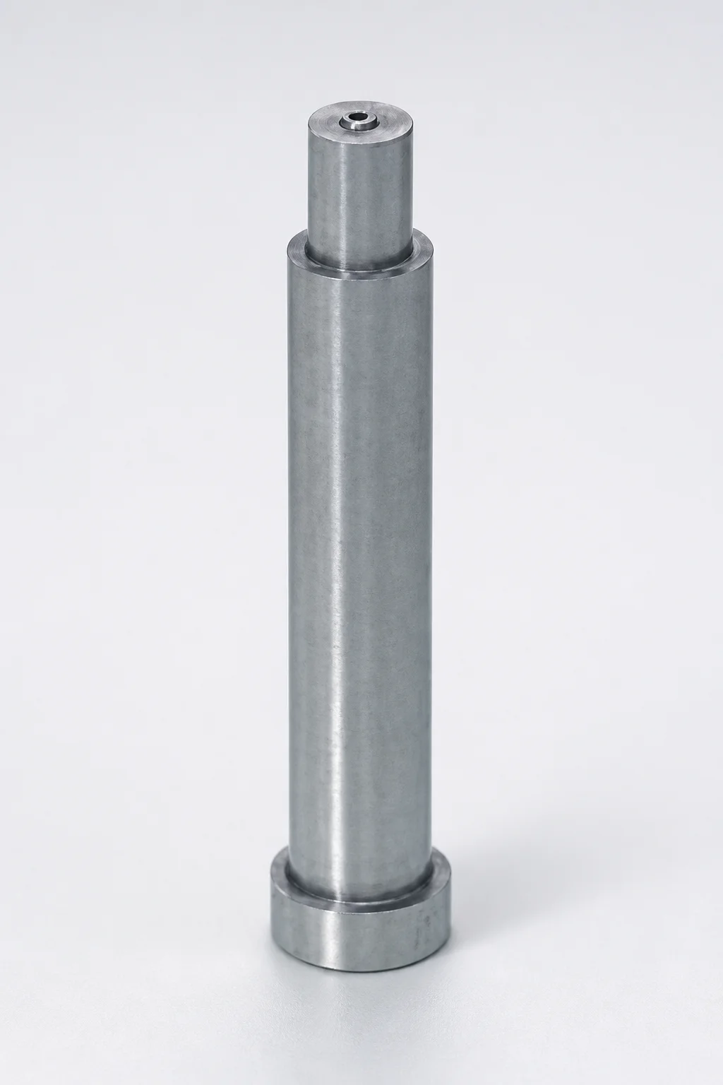
SKH51 Steel Pin-Point Gate Bushings with Head - Round Gate Transition (SR)
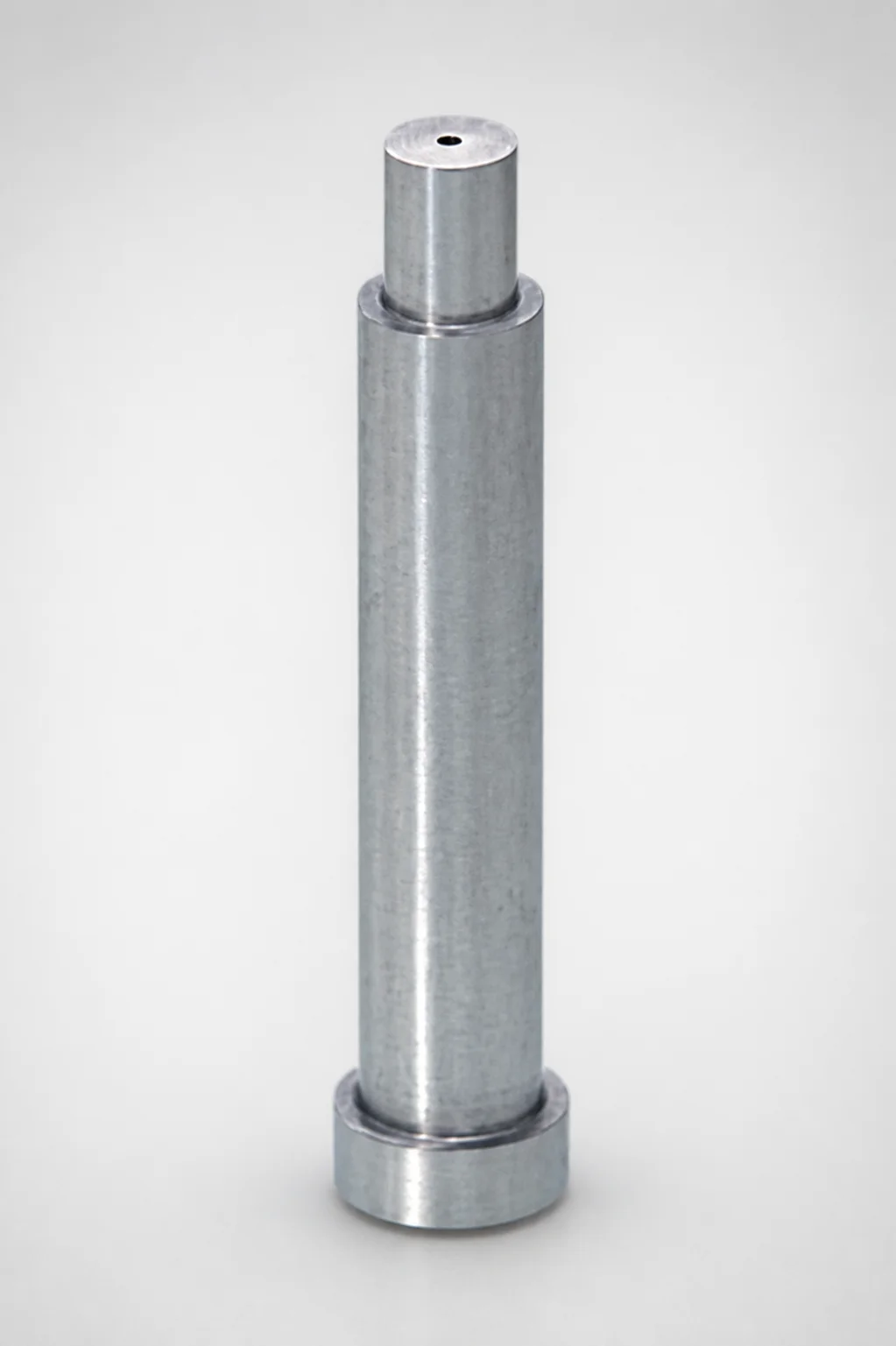
JIS Standard SKH51 Steel Pin-Point Gate Bushings (PGHTBL) with Head
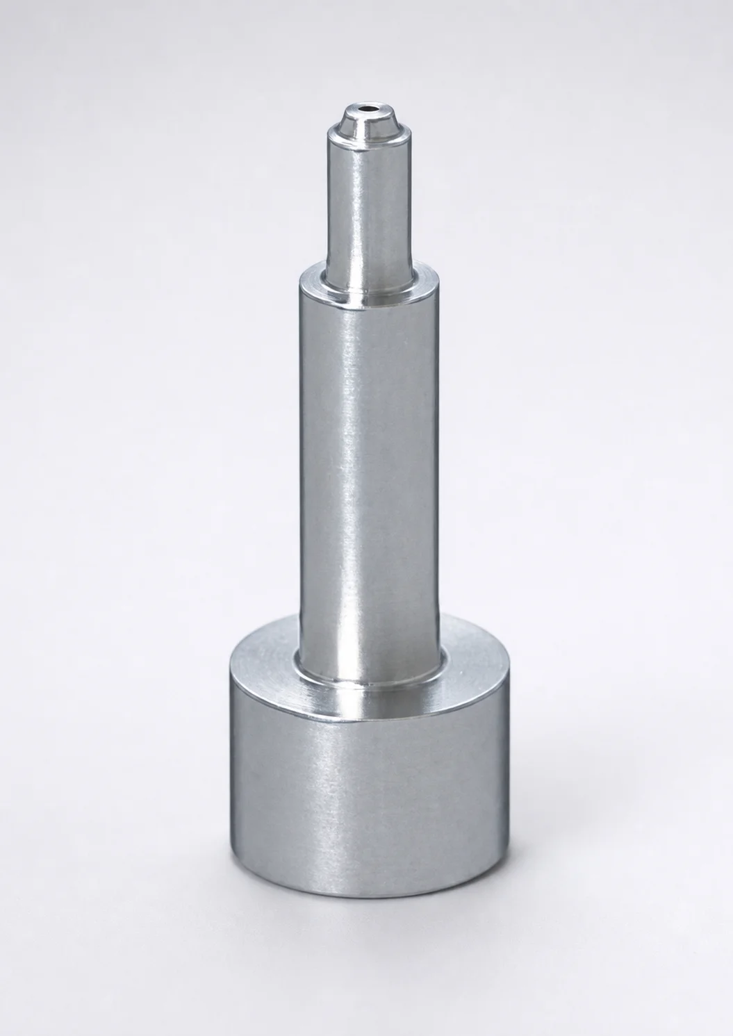
SKH51 Steel Pin-Point Gate Bushings with Head - Round Gate Transition
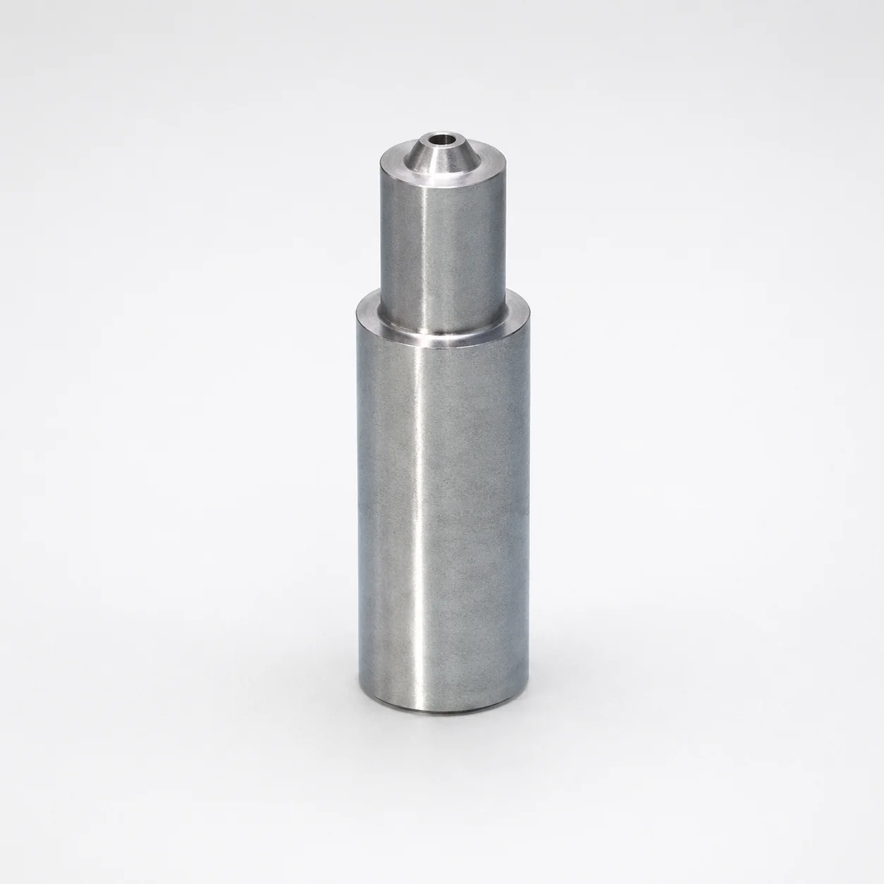
SKH51 Steel Pin-Point Gate Bushings Round Gate Transition SR
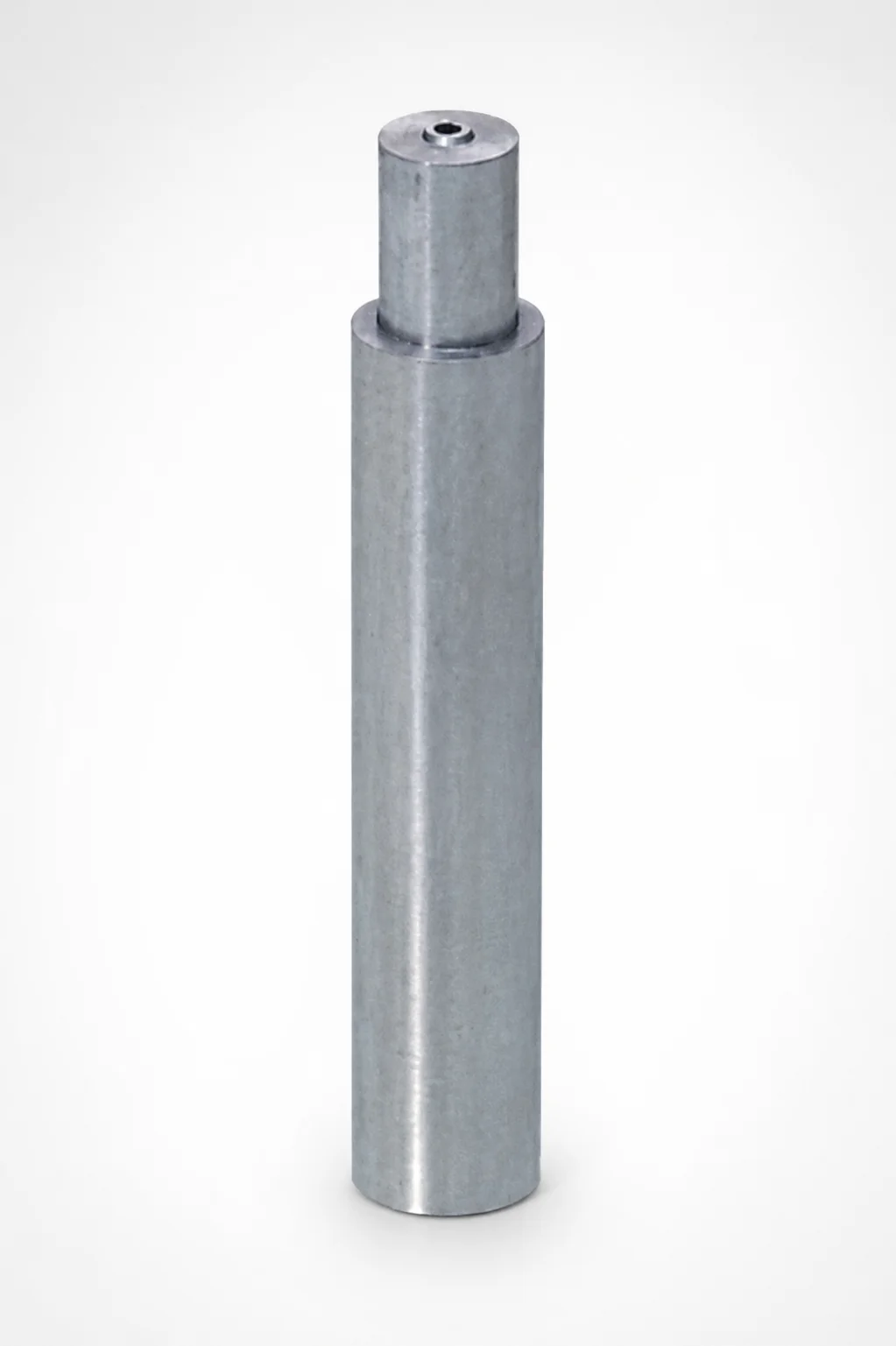
JIS Standard SKH51 Steel Pin-Point Gate Bushings Round Gate Transition SR
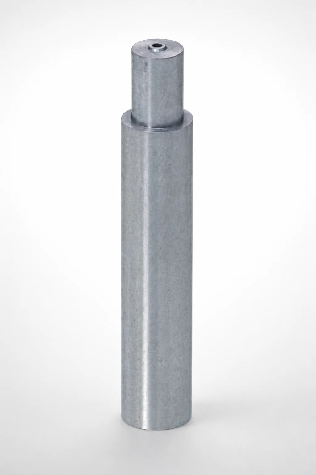
SKH51 Steel Pin-Point Gate Bushings Angle Gate Transition
Need Custom Specifications?
Our engineering team can help with custom configurations, material selection, and volume pricing.