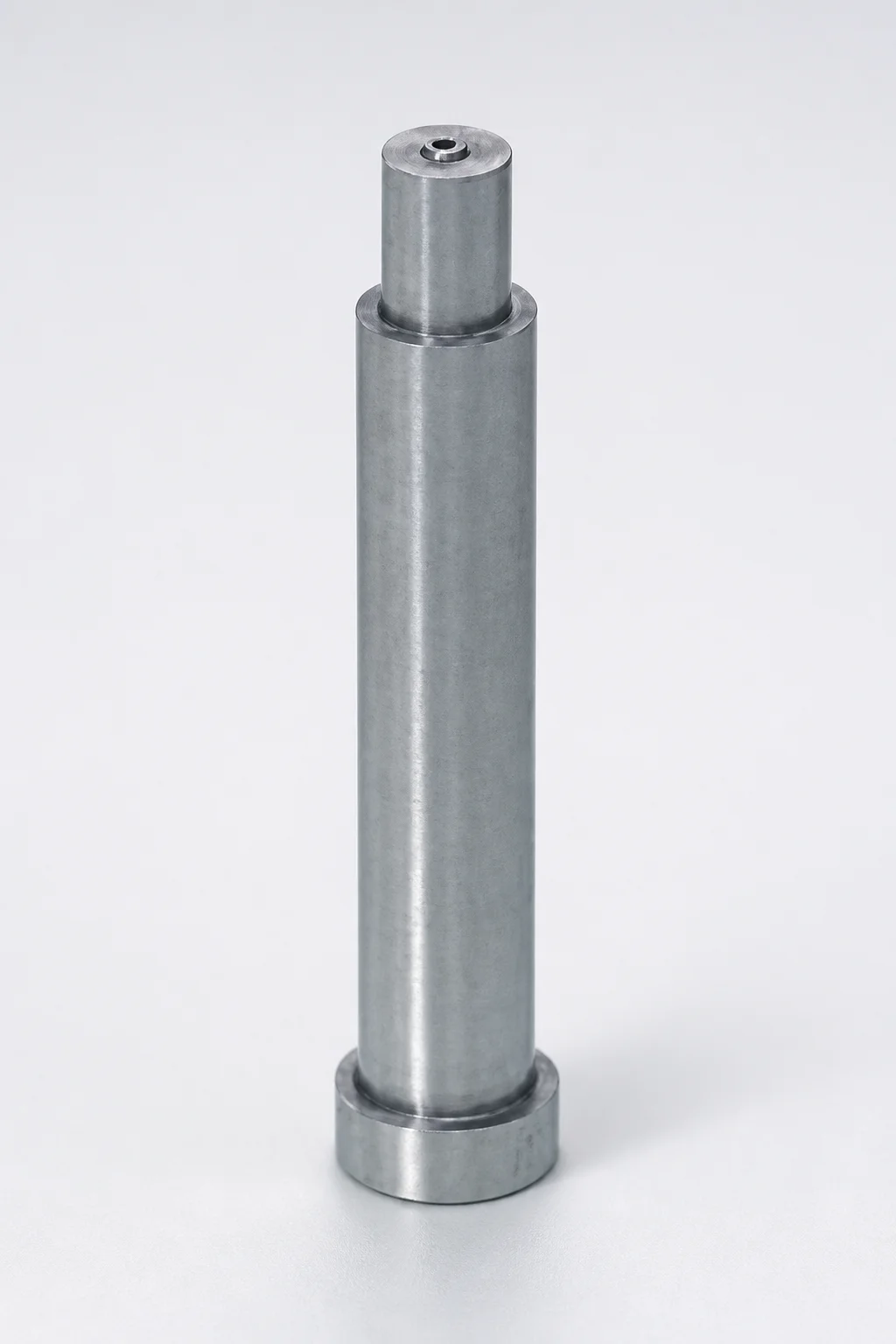
SKH51 Steel Pin-Point Gate Bushings with Head - Round Gate Transition (SR)
Pin-point gate bushings with head (SKH51 steel) with a round gate transition (SR) provide stable pin-point gating and smooth flow entry in precision molds. The stepped SR tip geometry helps support controlled runner gate formation for reliable cycle performance.
- Round gate transition (SR) supports consistent pin-point gating during injection
- SKH51 steel construction with hardening steel performance for wear resistance
- Controlled fit with D-dimension tolerance 0/-0.005 for repeatable assembly
- Used in molds requiring pinpoint gate control and repeatable part filling
Specifications
35 configurations available
| Tip Shape | D (Outer diameter) (mm) | A (Secondary sprue angle) (°) | C (Tip length) (mm) | K (Cutting angle) (°) | L (L dimension) (mm) | P (Tip diameter) (mm) | R (Tip R) (mm) | S (Tip angle) (°) | V (Tip diameter) (mm) | type |
|---|---|---|---|---|---|---|---|---|---|---|
| 1A | 2 | 1 ~ 3 | 0.2 ~ 0.4 | 20 ~ 30 | 10 ~ 20 | 0.3 ~ 0.5 | - | - | 1.3 ~ 1.9 | - |
| 1A | 2.5 | 1 ~ 3 | 0.2 ~ 0.5 | 20 ~ 30 | 10 ~ 25 | 0.3 ~ 0.6 | - | - | 1.5 ~ 2.4 | - |
| 1A | 3 | 1 ~ 3 | 0.3 ~ 0.8 | 20 ~ 30 | 20 ~ 40 | 0.5 ~ 0.9 | - | - | 2 ~ 2.9 | - |
| 1A | 4 | 1 ~ 3 | 0.3 ~ 0.8 | 20 ~ 30 | 20 ~ 40 | 0.6 ~ 1.2 | - | - | 2.5 ~ 3.9 | - |
| 1A | 5 | 1 ~ 3 | 0.5 ~ 1.5 | 20 ~ 30 | 20 ~ 60 | 0.8 ~ 1.5 | - | - | 3.5 ~ 4.9 | - |
| 1A | 6 | 1 ~ 3 | 0.5 ~ 1.5 | 20 ~ 30 | 20 ~ 60 | 1 ~ 1.6 | - | - | 4 ~ 5.9 | - |
| 1A | 8 | 1 ~ 3 | 0.5 ~ 1.5 | 20 ~ 30 | 20 ~ 60 | 1.2 ~ 1.6 | - | - | 4.5 ~ 7.9 | - |
| 2A | 2 | 1 ~ 3 | - | 20 ~ 30 | 10 ~ 20 | 0.3 ~ 0.5 | - | - | - | - |
| 2A | 2.5 | 1 ~ 3 | - | 20 ~ 30 | 10 ~ 25 | 0.3 ~ 0.6 | - | - | - | - |
| 2A | 3 | 1 ~ 3 | - | 20 ~ 30 | 20 ~ 40 | 0.5 ~ 0.9 | - | - | - | - |
| 2A | 4 | 1 ~ 3 | - | 20 ~ 30 | 20 ~ 40 | 0.6 ~ 1.2 | - | - | - | - |
| 2A | 5 | 1 ~ 3 | - | 20 ~ 30 | 20 ~ 60 | 0.8 ~ 1.5 | - | - | - | - |
| 2A | 6 | 1 ~ 3 | - | 20 ~ 30 | 20 ~ 60 | 1 ~ 1.6 | - | - | - | - |
| 2A | 8 | 1 ~ 3 | - | 20 ~ 30 | 20 �� 60 | 1.2 ~ 1.6 | - | - | - | - |
| 3A | 2 | 1 ~ 3 | 0.2 ~ 0.4 | 20 ~ 30 | 10 ~ 25 | 0.3 ~ 0.5 | - | 1 ~ 45 | - | - |
| 3A | 2.5 | 1 ~ 3 | 0.2 ~ 0.5 | 20 ~ 30 | 10 ~ 25 | 0.3 ~ 0.6 | - | 1 ~ 45 | - | - |
| 3A | 3 | 1 ~ 3 | 0.3 ~ 0.8 | 20 ~ 30 | 20 ~ 40 | 0.5 ~ 0.9 | - | 1 ~ 45 | - | - |
| 3A | 4 | 1 ~ 3 | 0.3 ~ 0.8 | 20 ~ 30 | 20 ~ 40 | 0.6 ~ 1.2 | - | 1 ~ 45 | - | - |
| 3A | 5 | 1 ~ 3 | 0.5 ~ 1.5 | 20 ~ 30 | 20 ~ 60 | 0.8 ~ 1.5 | - | 1 ~ 45 | - | - |
| 3A | 6 | 1 ~ 3 | 0.5 ~ 1.5 | 20 ~ 30 | 20 ~ 60 | 1 ~ 1.6 | - | 1 ~ 50 | - | - |
| 3A | 8 | 1 ~ 3 | 0.5 ~ 1.5 | 20 ~ 30 | 20 ~ 60 | 1.2 ~ 1.6 | - | 1 ~ 60 | - | - |
| 4A | 2 | 1 ~ 3 | 0.2 ~ 0.4 | 20 ~ 30 | 10 ~ 20 | 0.3 ~ 0.5 | 0.4 ~ 0.8 | - | - | - |
| 4A | 2.5 | 1 ~ 3 | 0.2 ~ 0.5 | 20 ~ 30 | 10 ~ 25 | 0.3 ~ 0.6 | 0.6 ~ 1 | - | - | - |
| 4A | 3 | 1 ~ 3 | 0.3 ~ 0.8 | 20 ~ 30 | 20 ~ 40 | 0.5 ~ 0.9 | 0.8 ~ 1.5 | - | - | - |
| 4A | 4 | 1 ~ 3 | 0.3 ~ 0.8 | 20 ~ 30 | 20 ~ 40 | 0.6 ~ 1.2 | 0.8 ~ 1.5 | - | - | - |
| 4A | 5 | 1 ~ 3 | 0.5 ~ 1.5 | 20 ~ 30 | 20 ~ 60 | 0.8 ~ 1.5 | 1 ~ 2 | - | - | - |
| 4A | 6 | 1 ~ 3 | 0.5 ~ 1.5 | 20 ~ 30 | 20 ~ 60 | 1 ~ 1.6 | 1.5 ~ 3 | - | - | - |
| 4A | 8 | 1 ~ 3 | 0.5 ~ 1.5 | 20 ~ 30 | 20 ~ 60 | 1.2 ~ 1.6 | 2 ~ 4 | - | - | - |
| 5A | 2 | 1 ~ 3 | 0.2 ~ 0.4 | 20 ~ 30 | 10 ~ 20 | 0.3 ~ 0.6 | - | - | - | - |
| 5A | 2.5 | 1 ~ 3 | 0.2 ~ 0.5 | 20 ~ 30 | 10 ~ 25 | 0.3 ~ 0.6 | - | - | - | - |
| 5A | 3 | 1 ~ 3 | 0.3 ~ 0.8 | 20 ~ 30 | 20 ~ 40 | 0.5 ~ 0.9 | - | - | - | - |
| 5A | 4 | 1 ~ 3 | 0.3 ~ 0.8 | 20 ~ 30 | 20 ~ 40 | 0.6 ~ 1.2 | - | - | - | - |
| 5A | 5 | 1 ~ 3 | 0.5 ~ 1.5 | 20 ~ 30 | 20 ~ 60 | 0.8 ~ 1.5 | - | - | - | - |
| 5A | 6 | 1 ~ 3 | 0.5 ~ 1.5 | 20 ~ 30 | 20 ~ 60 | 1 ~ 1.6 | - | - | - | - |
| 5A | 8 | 1 ~ 3 | 0.5 ~ 1.5 | 20 ~ 30 | 20 ~ 60 | 1.2 ~ 1.6 | - | - | - | - |
Product Guide
Application Scenarios+
Pin-point gate bushings with a round gate transition are used in injection mold tooling where stable, low-shear gate entry is critical and the gate must form reliably at every cycle. This style supports controlled runner-to-gate transfer and helps maintain a consistent pin-point gate footprint, which is especially valuable when filling thin-wall or high-detail features.
- Automotive connector and sensor housings: The round transition (SR) promotes smooth flow entry and controlled gate formation, helping reduce knit lines and gate-related defects during repeated production cycles.
- Consumer electronics housings and snap-fit parts: Tight dimensional repeatability supports consistent part filling, improving surface quality at the gate area while minimizing cycle-to-cycle variation.
- Medical device components (non-biomedical-critical gate surfaces): The hard steel bushing construction is suited to precision molds that see high wear from frequent gate shearing and retraction.
The combination of the SR geometry and SKH51 steel is well-matched to pin-point gating applications that demand both smooth flow transition and durable, accurate gate formation.
Material & Process Details+
SKH51 steel pin-point gate bushings are selected for toolmakers seeking hard, wear-resistant performance at the gate-contact interface. In typical tool steel cross-references, SKH51 is commonly treated as similar to the AISI M2 family in high-speed steel performance terms (fine carbide structure enabling abrasion resistance).
- Heat treatment state: supplied in a hardened condition appropriate for cutting/shearing gate steel loads; follow the manufacturer’s process to confirm final hardness and stable dimensional performance.
- Hardness & wear resistance: expected high hardness in the ~60 HRC class, balancing abrasion resistance for repeated gate formation and shearing.
- Toughness trade-off: higher hardness improves wear life but can reduce impact toughness versus tougher, lower-hardness tool steels—so design for stable support and avoid excessive side loads.
If compared with more general mold steels (e.g., tempered pre-hard grades), SKH51’s hard, wear-focused character better targets pin-point gate surfaces where repeated contact and micro-abrasion are dominant.
Sizing & Selection Guide+
Select the bushing profile by matching the gate-transition geometry and tip dimensions to the required pin-point gate size and shearing behavior in the cavity/core. Use the specified variable ranges to choose the closest geometry, then verify clearance and assembly fit in the mold.
- D (outer diameter): choose within 2 ~ 8 mm to match the bush pocket and alignment features of the sprue system.
- Tip parameters: pick a tip shape (1A–5A), then set P (tip diameter 0.3 ~ 1.2 mm), R (tip R 0.4 ~ 4 mm), and V (tip diameter 1.3 ~ 4.5 mm) to define the actual gate throat and transition radius.
- Length: use L (10–20, 10–25, 20–40, 20–60, or 20–60+ mm depending on variant) to ensure full engagement where the bushing interfaces with the runner/gate land.
For assembly compatibility, the design supports a D-dimension tolerance 0/-0.005 mm; confirm mating hole tolerance and press-fit/locating strategy. Secondary sprue angle A = 1–3° and cutting angle K = 20–30° are fixed within the listed ranges—use these constraints when finalizing gate layout.
Frequently Asked Questions
How does the SR (round gate transition) geometry affect pin-point gate consistency and gate remnants?+
What should I check when selecting P (tip diameter) and R (tip radius) for a given gate throat size?+
Is the D outer diameter tolerance suitable for repeatable bushing installation in a sprue/gate pocket?+
Which L length range should I use to ensure proper engagement with the runner/gate interface?+
Why choose SKH51 for pinpoint gate bushings instead of a more general tool steel?+
Related Products
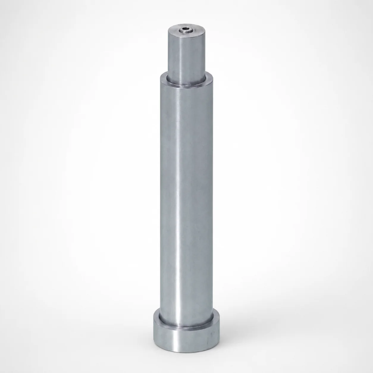
SKH51 Steel Pin-Point Gate Bushings with Head
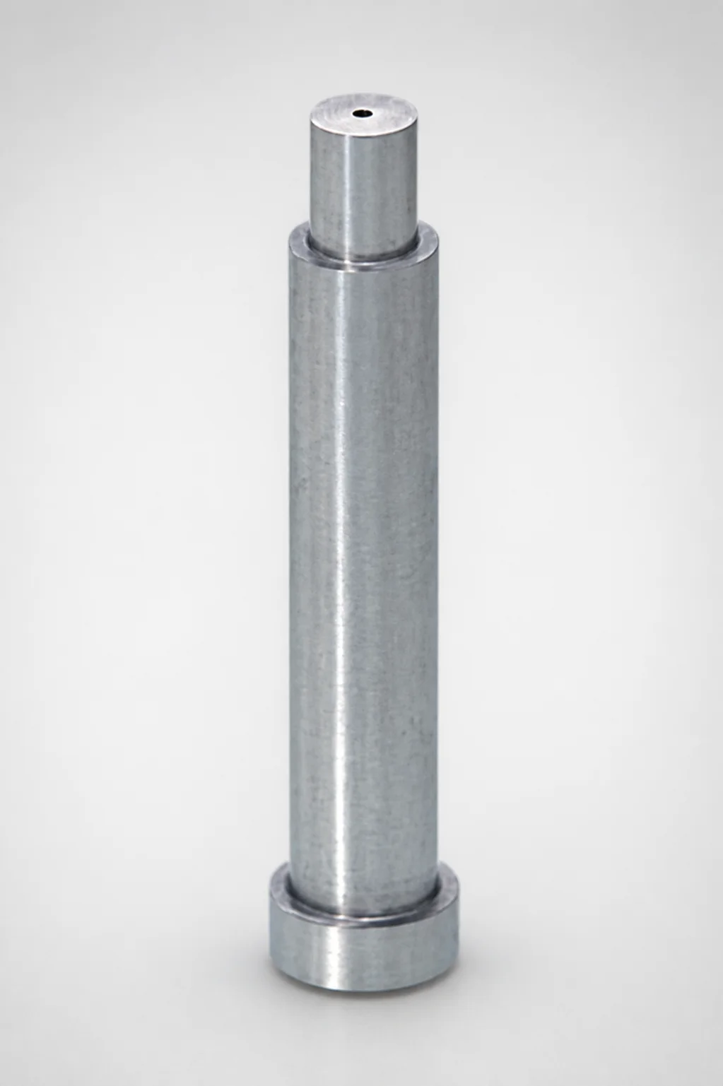
JIS Standard SKH51 Steel Pin-Point Gate Bushings (PGHTBL) with Head
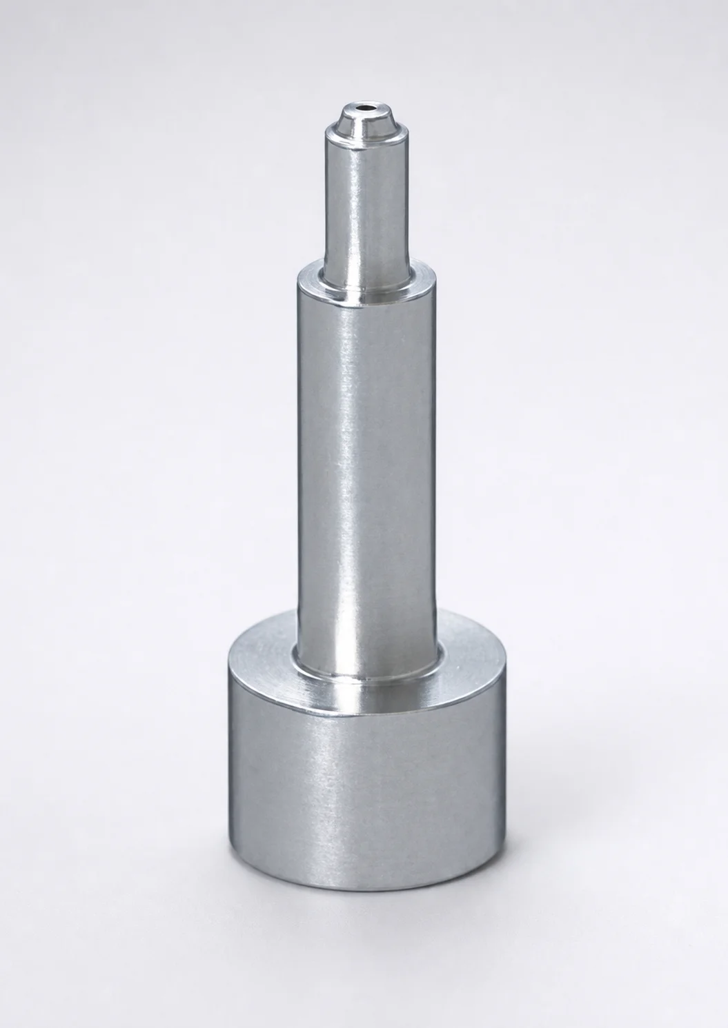
SKH51 Steel Pin-Point Gate Bushings with Head - Round Gate Transition
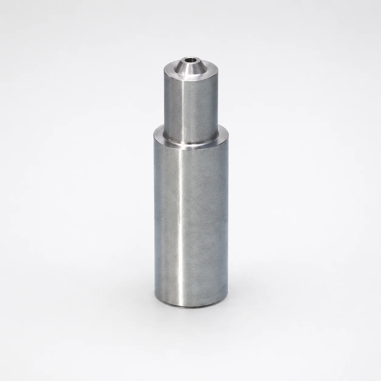
SKH51 Steel Pin-Point Gate Bushings Round Gate Transition SR
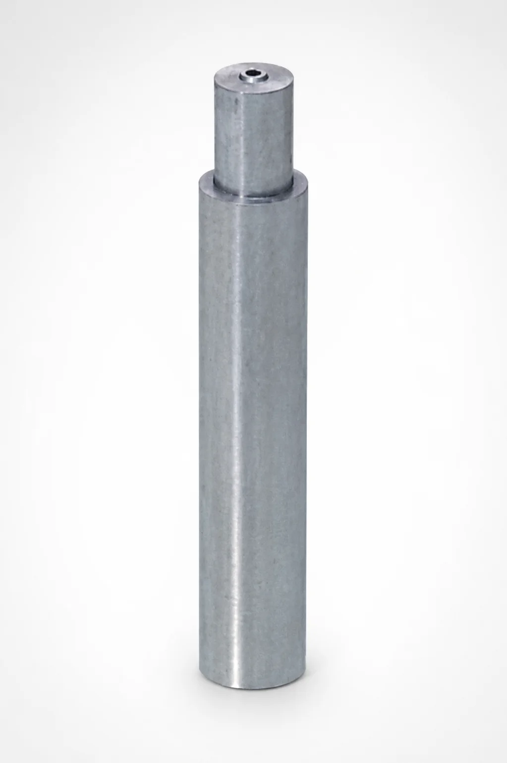
JIS Standard SKH51 Steel Pin-Point Gate Bushings Round Gate Transition SR
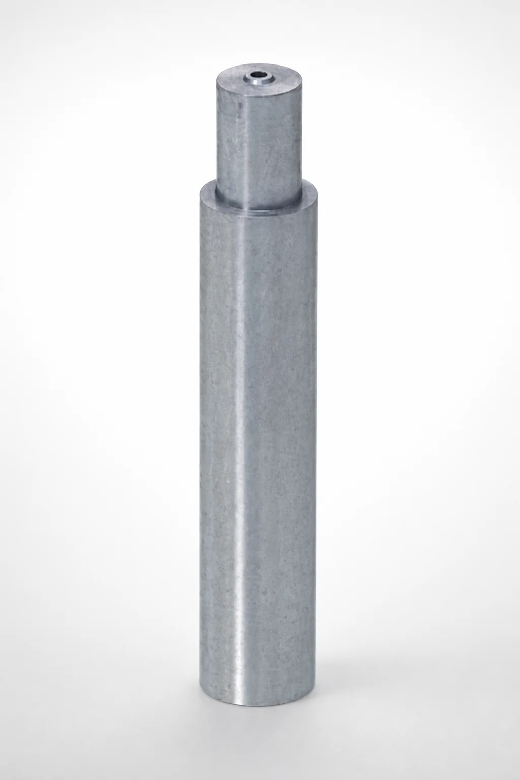
SKH51 Steel Pin-Point Gate Bushings Angle Gate Transition
Need Custom Specifications?
Our engineering team can help with custom configurations, material selection, and volume pricing.