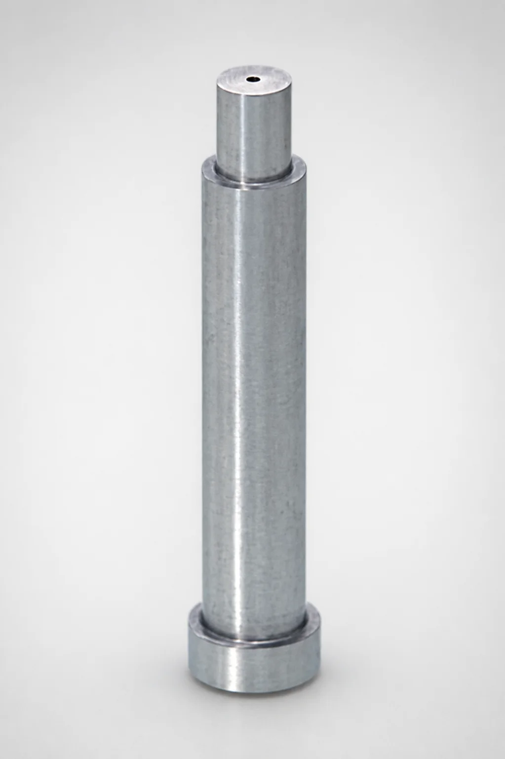
JIS Standard SKH51 Steel Pin-Point Gate Bushings (PGHTBL) with Head
Pin-Point Gate Bushings with Head (SKH51 steel) are designed for accurate round gate transitions using the PGHTBL structure. The pilot tip hole helps control runner/gate positioning for consistent molding output.
- PGHTBL head type for stable gate-area support during injection
- Built from SKH51 steel for wear resistance and long service life
- Controlled outer diameter tolerance reference of 0/-0.005 supports tight fit
- For tooling requiring precise gate transfer and repeatable alignment
Specifications
5 configurations available
| D (Outer diameter) (mm) | A (Secondary sprue angle) (°) | B (Length excluding the lengths of head and tip) (mm) | G (Distance from gate tip to SR) (mm) | L (L dimension) (mm) | P (Tip diameter) (mm) | SR (mm) | type |
|---|---|---|---|---|---|---|---|
| 3 | 1 ~ 3 | 5 ~ 10.5 | 1.2 ~ 3 | 20 ~ 40 | 0.4 ~ 0.6 | 1 | - |
| 4 | 1 ~ 3 | 5 ~ 31.5 | 1.2 ~ 3 | 20 ~ 40 | 0.4 ~ 0.8 | 1 ~ 1.25 | - |
| 5 | 1 ~ 3 | 5 ~ 32.5 | 1.5 ~ 4 | 20 ~ 60 | 0.6 ~ 0.8 | 1.25 ~ 1.5 | - |
| 6 | 1 ~ 3 | 5 ~ 30 | 1.5 ~ 4 | 20 ~ 60 | 0.8 | 1.25 ~ 1.5 | - |
| 8 | 1 ~ 3 | 6.5 ~ 31.5 | 1.5 ~ 4 | 20 ~ 60 | 0.8 | 1.5 ~ 2 | - |
Product Guide
Application Scenarios+
Pin-point gate bushings are used in injection mold tooling to create controlled, repeatable transitions between the sprue/runner and the final round gate. This variant’s pilot tip hole supports precise alignment of the gate position, helping reduce part-to-part variation in fill and packing.
- Automotive connector and terminal molds: Use the round-transition geometry to stabilize gate-area support during injection; the head type helps maintain reliable seating under cycling.
- Consumer and appliance housings with small round gates: Select the matching tip diameter and SR range to tune the gate opening and ensure consistent gate formation during fast fills.
- General precision housings requiring alignment repeatability: The SKH51 wear-resistant steel supports long production runs where bushings experience frequent thermal cycling and contact loads.
Compared with non-piloted gate bushings, the PGHTBL structure improves positioning repeatability by locating the transition area with the pilot tip hole, which is critical for maintaining the target gate location over time.
Material & Process Details+
This bushing is manufactured from JIS Standard SKH51 steel, a high-speed steel grade commonly used for wear-critical mold components. SKH51 is known for excellent wear resistance at the contact surfaces near the gate interface, where sliding and impact loads can occur during ejection and thermal cycling.
- Typical hardness: SKH51 is commonly supplied in the quenched & tempered range and is often used at high hardness levels (commonly around the 60–62 HRC class) to balance wear and toughness.
- Heat treatment (process): Hardening followed by tempering is used to achieve the working hardness; in service, localized wear and micro-chipping resistance are improved at the gate-contact tip.
- Trade-off: Higher hardness improves wear resistance, but can reduce toughness versus lower-hardness steels—so correct bushing sizing and proper alignment are important.
Compared with more general tool steels, SKH51’s high-speed steel characteristics provide a more robust solution for long-life gate bushings subjected to repeated contact at the pin-point transition.
Sizing & Selection Guide+
To select the correct PGHTBL steel pin-point gate bushing, match the mold’s required round gate transition dimensions to the offered spec ranges. Start with D (outer diameter)—available in 3, 4, 5, 6, 8 mm—to ensure the bushing fits the corresponding sprue bushing pocket and maintains concentricity to the gate.
- Gate geometry tuning: Choose P (tip diameter) from 0.4–0.6, 0.4–0.8, 0.6–0.8, or 0.8 mm and select the SR range (1, 1–1.25, 1.25–1.5, 1.5–2 mm) to define the transition and pilot-tip shaping.
- Length setup: Match B (5–10.5 up to 5–32.5 or 6.5–31.5 mm, depending on the selected variant) and overall L (20–40 or 20–60 mm) to the mold plate thickness and runner/sprue layout.
- Alignment reference: Use G (1.2–3 or 1.5–4 mm) for the required distance from gate tip to SR feature.
For fit, the product description indicates an outer diameter tolerance reference of 0/-0.005 mm, so plan cavity/core machining and clearances accordingly to achieve a stable seating without interference.
Frequently Asked Questions
How do I choose the correct D (outer diameter) for a pin-point gate bushing with head?+
Select D from 3, 4, 5, 6, or 8 mm based on the diameter of the bushing pocket in the mold plate. The provided outer diameter tolerance reference is 0/-0.005 mm, so account for the lower end tolerance during fit-up. If you’re targeting a tight locating fit, verify both the pocket size and surface finish to maintain alignment of the pilot tip hole.
What should I use to tune the round transition: P (tip diameter) or SR, and how are the ranges defined?+
Use P to set the tip diameter (options include 0.4–0.6, 0.4–0.8, 0.6–0.8, or 0.8 mm) and use SR to set the SR feature range (1, 1–1.25, 1.25–1.5, 1.5–2 mm). In combination, these dimensions define the pin-point/gate transition profile that affects gate formation and repeatability. Keep G (distance from gate tip to SR) consistent with your runner/sprue design requirements.
How do I match B and L to my mold plate thickness and sprue/runner layout?+
Use B (length excluding the head and tip) and L (overall L dimension) to match the distance from the reference face to the transition/gate area. Available ranges include B: 5–10.5, 5–31.5, 5–32.5, 5–30, or 6.5–31.5 mm and L: 20–40 or 20–60 mm. Confirm that the gate tip location relative to the runner/sprue interface can be achieved with your chosen G (1.2–3 or 1.5–4 mm).
Does the secondary sprue angle A affect gate transfer on this PGHTBL bushing?+
Yes. The secondary sprue angle A is fixed in this series at 1° to 3°, which influences how the round transition aligns with the runner/sprue entry. When optimizing flow and gate formation, verify that your sprue/runner angle setup matches this range so the pilot tip hole can support consistent positioning.
Why is SKH51 selected for pin-point gate bushings, and what wear behavior should I expect?+
The bushing uses JIS SKH51 steel, chosen for wear resistance at the gate transition area. In tooling service, higher hardness achieved via hardening and tempering improves resistance to wear and micro-damage at the tip and seating surfaces, though it can reduce toughness compared with lower-hardness steels. If your process involves frequent thermal cycling or high contact loads, SKH51’s wear-oriented performance helps extend service intervals.
Related Products
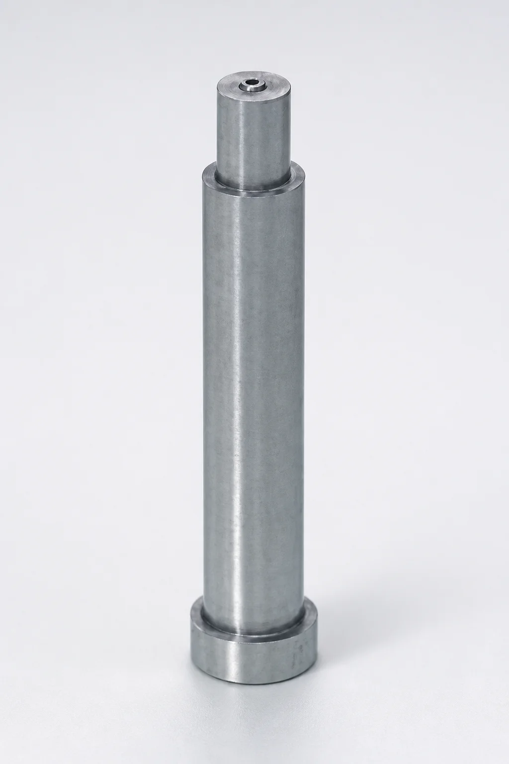
SKH51 Steel Pin-Point Gate Bushings with Head - Round Gate Transition (SR)
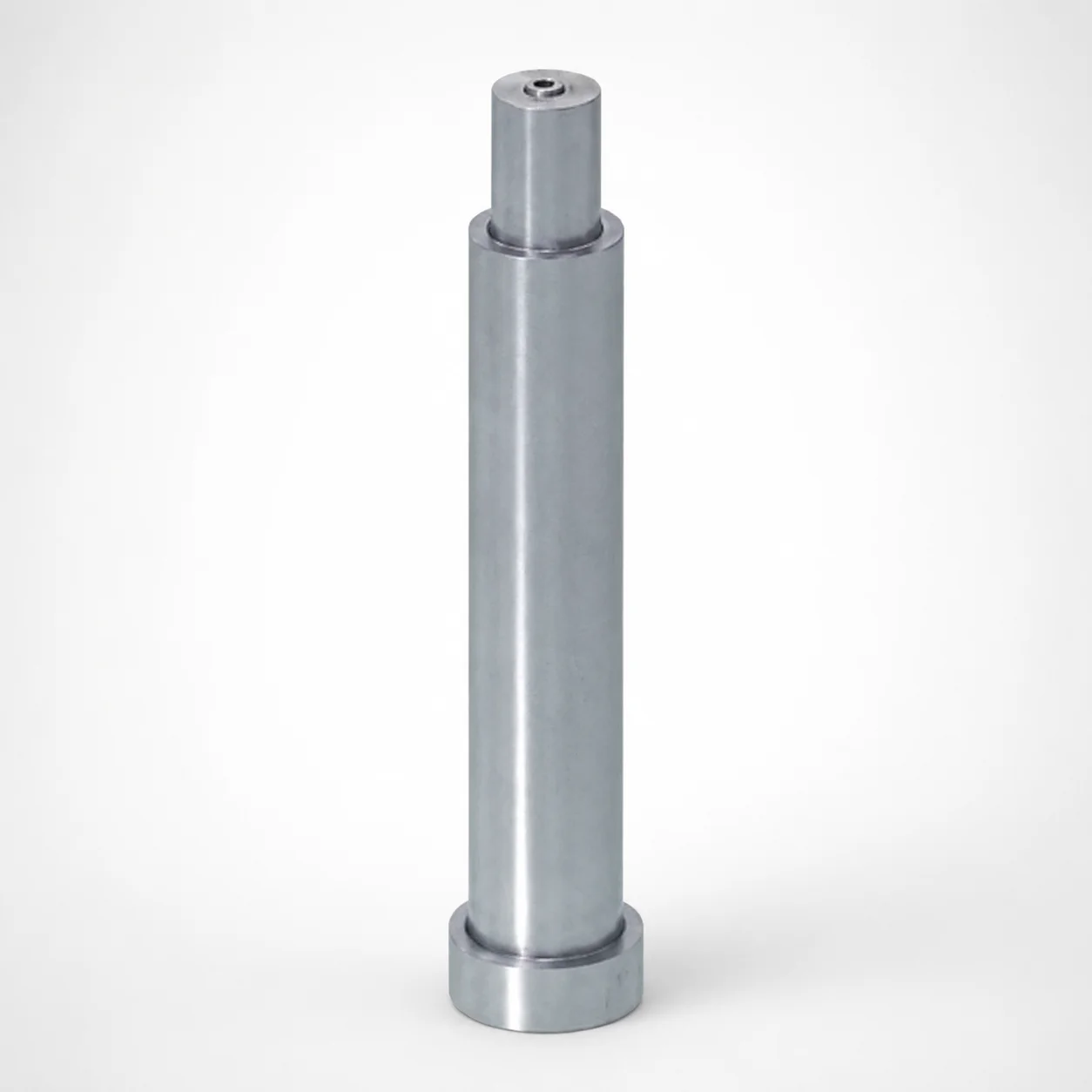
SKH51 Steel Pin-Point Gate Bushings with Head
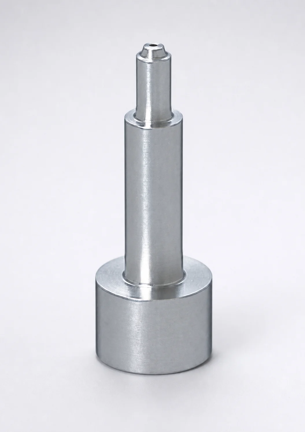
SKH51 Steel Pin-Point Gate Bushings with Head - Round Gate Transition
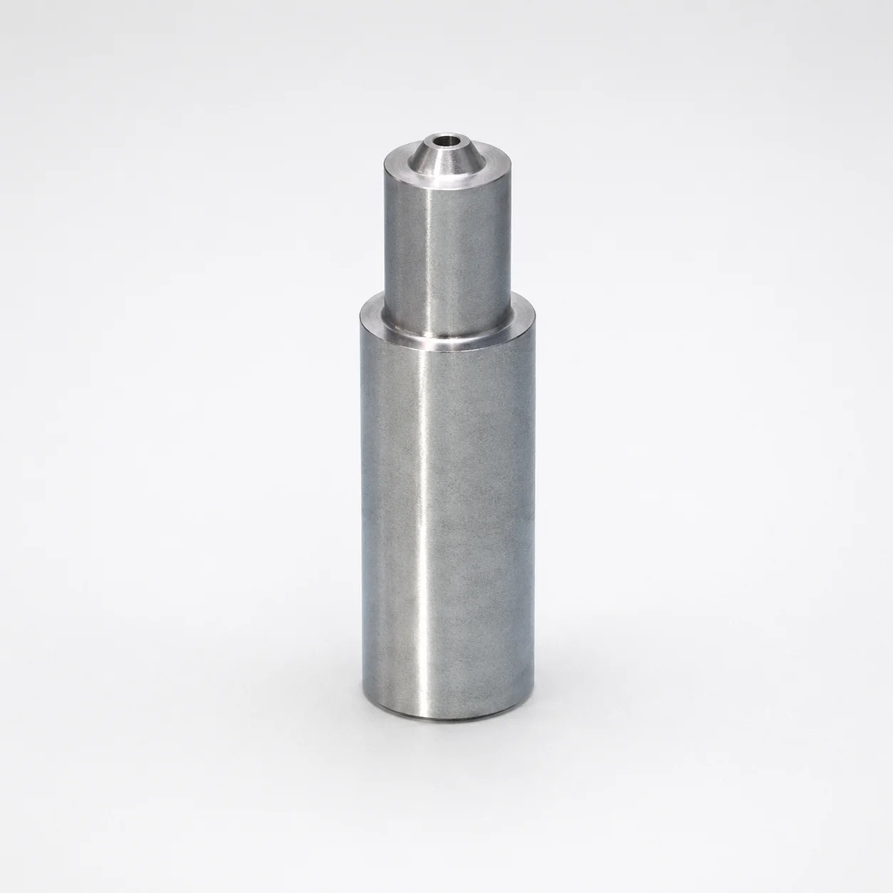
SKH51 Steel Pin-Point Gate Bushings Round Gate Transition SR
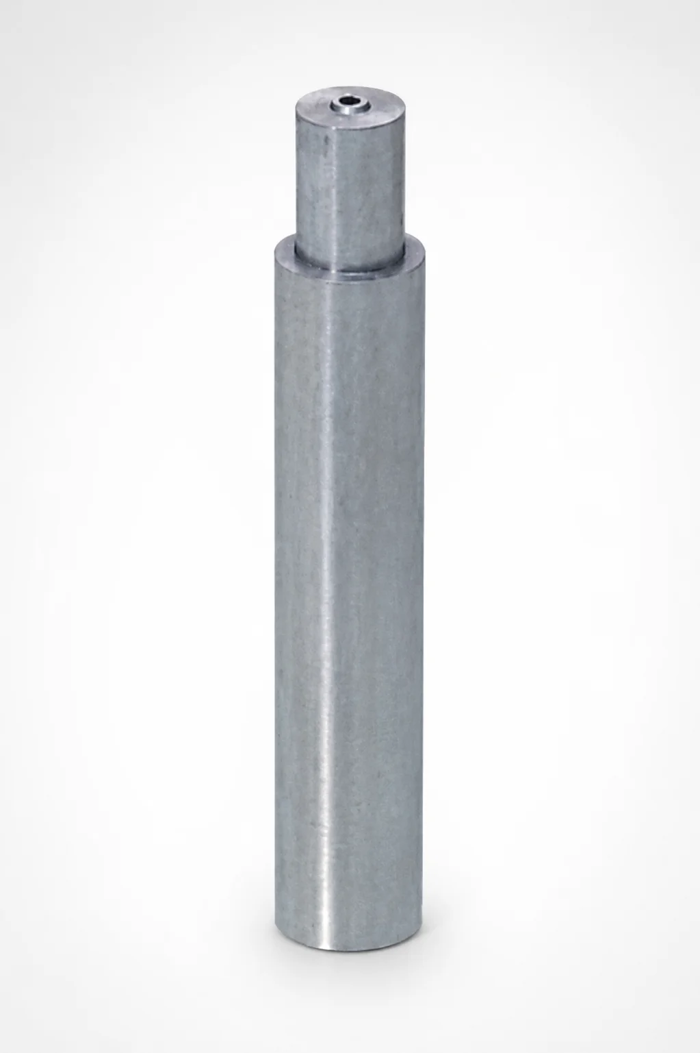
JIS Standard SKH51 Steel Pin-Point Gate Bushings Round Gate Transition SR
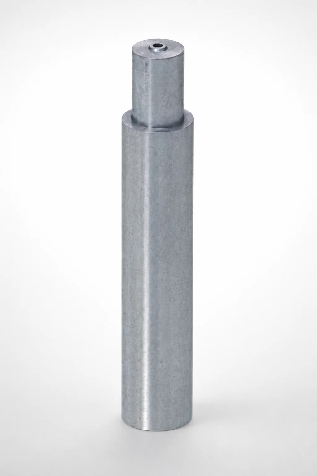
SKH51 Steel Pin-Point Gate Bushings Angle Gate Transition
Need Custom Specifications?
Our engineering team can help with custom configurations, material selection, and volume pricing.