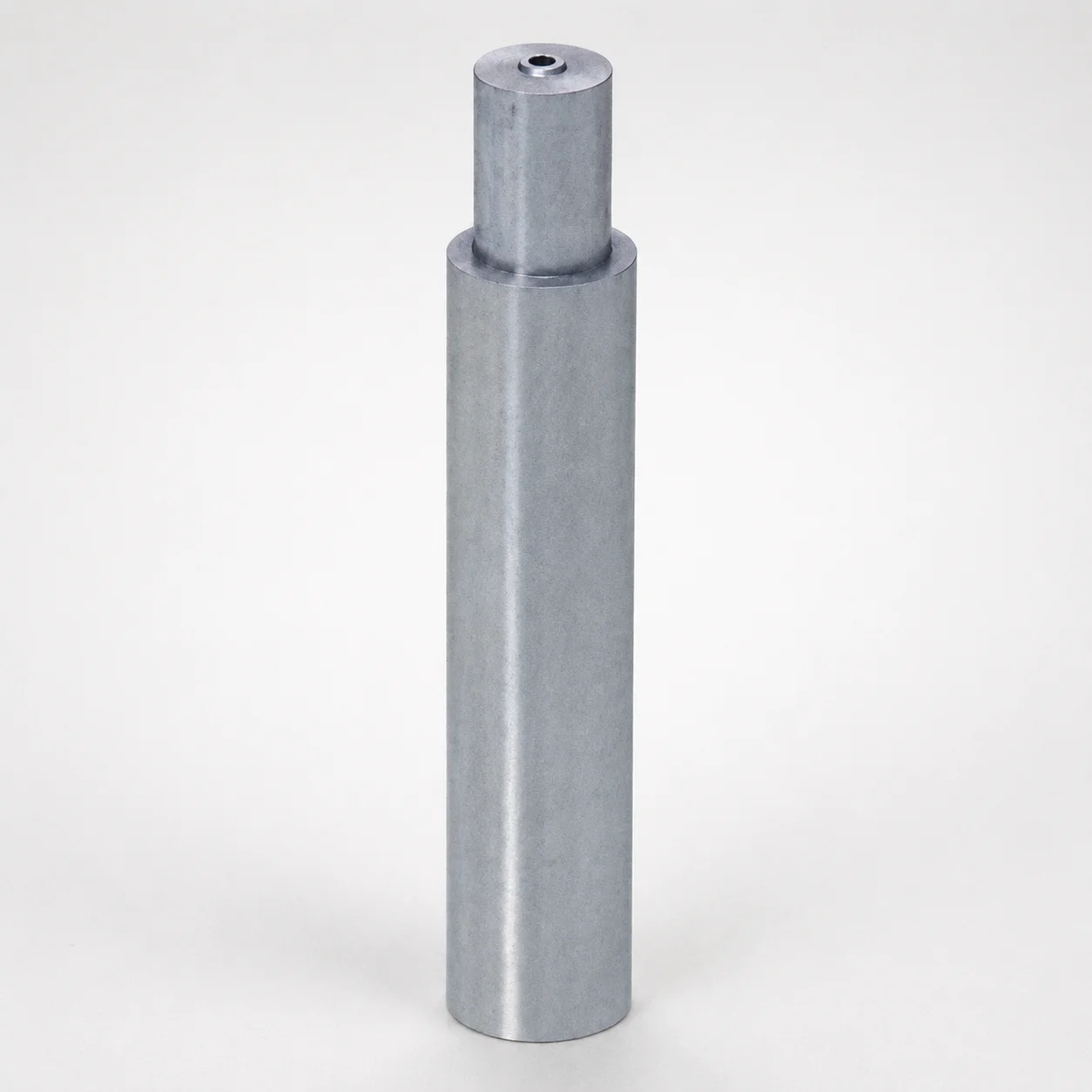
SKH51 Steel Pin-Point Gate Bushings Round Gate Transition
Pin-Point Gate Bushings (SKH51 steel) provide a stable round gate transition to help position and guide the melt for consistent filling. The robust bushing body is designed for repeatable mold setup and dependable gate formation in production.
- Round gate transition geometry supports accurate gate alignment during injection cycles
- Quenched SKH51 steel offers wear resistance for long-term mold operation
- Maintains P dimension tolerance (±0.01) for reliable assembly and fit consistency
- Suitable for injection molds requiring pin-point gate bushings with controlled gate transition
Specifications
24 configurations available
| Tip Type | Tip Shape | P Dimension Tolerance | Tip Straight Tolerance | D (Outer diameter) (mm) | A (Taper angle) (°) | B (Length excluding the lengths of head and tip) (mm) | C (Tip length) (mm) | G (Tip tapered length) (mm) | K (Cutting angle) (°) | L (L dimension) (mm) | P (Tip diameter) (mm) | R (Tip R) (mm) | S (Tip angle) (°) | V (Tip diameter) (mm) | type |
|---|---|---|---|---|---|---|---|---|---|---|---|---|---|---|---|
| Normal | 1A | ±0.01 | 0 to 0.2 | 6 | 1 ~ 3 | 5 ~ 20 | 0.5 ~ 1.5 | 0.8 ~ 1.2 | 20 ~ 50 | 15 ~ 40 | 0.5 ~ 0.6 | - | - | 4 ~ 5.9 | - |
| Normal | 1A | ±0.01 | 0 to 0.2 | 8 | 1 ~ 3 | 5 ~ 20 | 0.5 ~ 1.5 | 0.8 ~ 1.5 | 20 ~ 60 | 15 ~ 40 | 0.8 ~ 1.4 | - | - | 4.5 ~ 7.9 | - |
| Normal | 1A | ±0.01 | 0 to 0.2 | 10 | 1 ~ 3 | 5 ~ 20 | 0.5 ~ 1.5 | 0.8 ~ 1.5 | 20 ~ 60 | 15 ~ 40 | 1.2 ~ 1.6 | - | - | 5 ~ 9.9 | - |
| Normal | 2A | ±0.01 | 0 to 0.2 | 6 | 1 ~ 3 | 5 ~ 20 | - | 0.8 ~ 1.2 | 20 ~ 50 | 15 ~ 40 | 0.5 ~ 0.6 | - | - | - | - |
| Normal | 2A | ±0.01 | 0 to 0.2 | 8 | 1 ~ 3 | 5 ~ 20 | - | 0.8 ~ 1.5 | 20 ~ 60 | 15 ~ 40 | 0.8 ~ 1.4 | - | - | - | - |
| Normal | 2A | ±0.01 | 0 to 0.2 | 10 | 1 ~ 3 | 5 ~ 20 | - | 0.8 ~ 1.5 | 20 ~ 60 | 15 ~ 40 | 1.2 ~ 1.6 | - | - | - | - |
| Normal | 3A | ±0.01 | 0 to 0.2 | 6 | 1 ~ 3 | 5 ~ 20 | 0.5 ~ 1.5 | 0.8 ~ 1.2 | 20 ~ 50 | 15 ~ 40 | 0.5 ~ 0.6 | - | 1 ~ 50 | - | - |
| Normal | 3A | ±0.01 | 0 to 0.2 | 8 | 1 ~ 3 | 5 ~ 20 | 0.5 ~ 1.5 | 0.8 ~ 1.5 | 20 ~ 60 | 15 ~ 40 | 0.8 ~ 1.4 | - | 1 ~ 60 | - | - |
| Normal | 3A | ±0.01 | 0 to 0.2 | 10 | 1 ~ 3 | 5 ~ 20 | 0.5 ~ 1.5 | 0.8 ~ 1.5 | 20 ~ 60 | 15 ~ 40 | 1.2 ~ 1.6 | - | 1 ~ 60 | - | - |
| Normal | 4A | ±0.01 | 0 to 0.2 | 6 | 1 ~ 3 | 5 ~ 20 | 0.5 ~ 1.5 | 0.8 ~ 1.2 | 20 ~ 50 | 15 ~ 40 | 0.5 ~ 0.6 | 1.5 ~ 3 | - | - | - |
| Normal | 4A | ±0.01 | 0 to 0.2 | 8 | 1 ~ 3 | 5 ~ 20 | 0.5 ~ 1.5 | 0.8 ~ 1.5 | 20 ~ 60 | 15 ~ 40 | 0.8 ~ 1.4 | 2 ~ 4 | - | - | - |
| Normal | 4A | ±0.01 | 0 to 0.2 | 10 | 1 ~ 3 | 5 ~ 20 | 0.5 ~ 1.5 | 0.8 ~ 1.5 | 20 ~ 60 | 15 ~ 40 | 1.2 ~ 1.6 | 2.5 ~ 5 | - | - | - |
| Normal | 5A | ±0.01 | 0 to 0.2 | 6 | 1 ~ 3 | 5 ~ 20 | 0.5 ~ 1.5 | 0.8 ~ 1.2 | 20 ~ 50 | 15 ~ 40 | 0.5 ~ 0.6 | - | - | - | - |
| Normal | 5A | ±0.01 | 0 to 0.2 | 8 | 1 ~ 3 | 5 ~ 20 | 0.5 ~ 1.5 | 0.8 ~ 1.5 | 20 ~ 60 | 15 ~ 40 | 0.8 ~ 1.4 | - | - | - | - |
| Normal | 5A | ±0.01 | 0 to 0.2 | 10 | 1 ~ 3 | 5 ~ 20 | 0.5 ~ 1.5 | 0.8 ~ 1.5 | 20 ~ 60 | 15 ~ 40 | 1.2 ~ 1.6 | - | - | - | - |
| Acute angle | 1A | - | 0 to 0.05 | 6 | 1 ~ 3 | 5 ~ 20 | 0.5 ~ 1.5 | 0.8 ~ 1.2 | 20 ~ 50 | 15 ~ 40 | 0.5 ~ 0.6 | - | - | 4 ~ 5.9 | - |
| Acute angle | 1A | - | 0 to 0.05 | 8 | 1 ~ 3 | 5 ~ 20 | 0.5 ~ 1.5 | 0.8 ~ 1.5 | 20 ~ 60 | 15 ~ 40 | 0.8 ~ 1.4 | - | - | 4.5 ~ 7.9 | - |
| Acute angle | 1A | - | 0 to 0.05 | 10 | 1 ~ 3 | 5 ~ 20 | 0.5 ~ 1.5 | 0.8 ~ 1.5 | 20 ~ 60 | 15 ~ 40 | 1.2 ~ 1.6 | - | - | 5 ~ 9.9 | - |
| Acute angle | 2A | - | 0 to 0.05 | 6 | 1 ~ 3 | 5 ~ 20 | - | 0.8 ~ 1.2 | 20 ~ 50 | 15 ~ 40 | 0.5 ~ 0.6 | - | - | - | - |
| Acute angle | 2A | - | 0 to 0.05 | 8 | 1 ~ 3 | 5 ~ 20 | - | 0.8 ~ 1.5 | 20 ~ 60 | 15 ~ 40 | 0.8 ~ 1.4 | - | - | - | - |
| Acute angle | 2A | - | 0 to 0.05 | 10 | 1 ~ 3 | 5 ~ 20 | - | 0.8 ~ 1.5 | 20 ~ 60 | 15 ~ 40 | 1.2 ~ 1.6 | - | - | - | - |
| Acute angle | 3A | - | 0 to 0.05 | 6 | 1 ~ 3 | 5 ~ 20 | 0.5 ~ 1.5 | 0.8 ~ 1.2 | 20 ~ 50 | 15 ~ 40 | 0.5 ~ 0.6 | - | 1 ~ 50 | - | - |
| Acute angle | 3A | - | 0 to 0.05 | 8 | 1 ~ 3 | 5 ~ 20 | 0.5 ~ 1.5 | 0.8 ~ 1.5 | 20 ~ 60 | 15 ~ 40 | 0.8 ~ 1.4 | - | 1 ~ 60 | - | - |
| Acute angle | 3A | - | 0 to 0.05 | 10 | 1 ~ 3 | 5 ~ 20 | 0.5 ~ 1.5 | 0.8 ~ 1.5 | 20 ~ 60 | 15 ~ 40 | 1.2 ~ 1.6 | - | 1 ~ 60 | - | - |
Product Guide
Application Scenarios+
Pin-point gate bushings are used in injection molds to create a stable, repeatable connection between the sprue and the gate. This SKH51 quenched steel bushing variant is especially suited for precision gate placement where consistent melt onset prevents short shots and jetting.
- Automotive connector and sensor housings: Use the round gate transition to maintain accurate gate alignment through repeated opening cycles, supporting consistent filling for thin ribs and high-gate-count layouts.
- Consumer electronics casings: The controlled taper (A: 1–3°) and governed tip geometry help form a reliable gate without excessive flash, improving surface appearance near the part gate.
- Medical device housings: Wear-resistant SKH51 helps sustain dimensional stability in high-run molds, supporting repeatable gate size and transition during long production batches.
Choose the correct tip type (Normal/Acute) and shape family to match your required gate transition profile and part-flow sensitivity.
Material & Process Details+
This bushing uses SKH51 quenched hardening steel, selected for its high wear resistance in gate-forming components. SKH51 is commonly aligned with AISI M2-equivalent high-speed steel performance levels, making it suitable for repeated thermal cycling and sliding contact during pin-point gate formation.
- Heat treatment: Quenched hardening construction, typically resulting in high hardness suitable for long mold runs.
- Hardness & performance: High hardness supports wear resistance at the gate tip; expect a trade-off where extreme hardness may reduce toughness compared with lower-alloy, water-hardened steels.
- Wear vs. toughness: For molds with frequent gate rework or abrasive additives, SKH51’s wear capability helps maintain tip dimensions; however, careful design for load concentration remains important.
Where other steels offer higher toughness, SKH51 is preferred when gate-tip wear control and dimensional stability across production are critical.
Sizing & Selection Guide+
Select dimensions by matching the bushing to the gate bushing seat and the required gate transition profile in the mold core/cavity system.
- Outer diameter (D): Choose D = 6, 8, or 10 mm to match your bushing bore. Confirm fit based on the mold plate machining size and your intended retention method.
- Tip diameter (P): Maintain the specified P tolerance ±0.01 and select P from 0.5–0.6, 0.8–1.4, or 1.2–1.6 mm to set the gate neck diameter.
- Gate transition geometry: Use the fixed taper angle A = 1–3°, tip length C = 0.5–1.5 mm, and base length B = 5–20 mm. Tip tapered length G = 0.8–1.2 or 0.8–1.5 mm and overall L = 15–40 mm help control penetration and transition length.
For best assembly repeatability, align the bushing’s controlled P diameter with the gate-forming cavity features; the fixed tolerance makes it easier to keep gate dimensions consistent across builds.
Frequently Asked Questions
Which SKH51 pin-point gate bushing dimensions most affect gate diameter and transition length?+
How do I choose between Normal and Acute tip types for injection gate performance?+
What outer diameter (D) options are available, and what should I verify for mold plate fit?+
Does this bushing’s SKH51 quenched hardening steel target wear resistance at the gate tip?+
How do taper angles and cutting angles (A and K) relate to flash risk and gate quality?+
Related Products
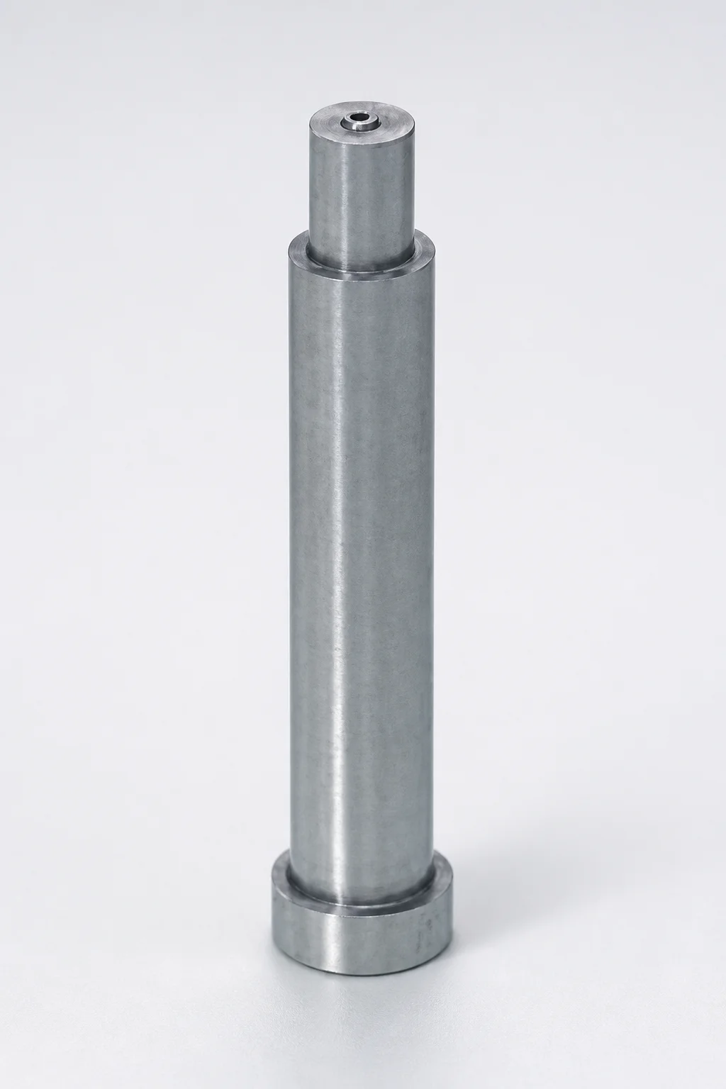
SKH51 Steel Pin-Point Gate Bushings with Head - Round Gate Transition (SR)
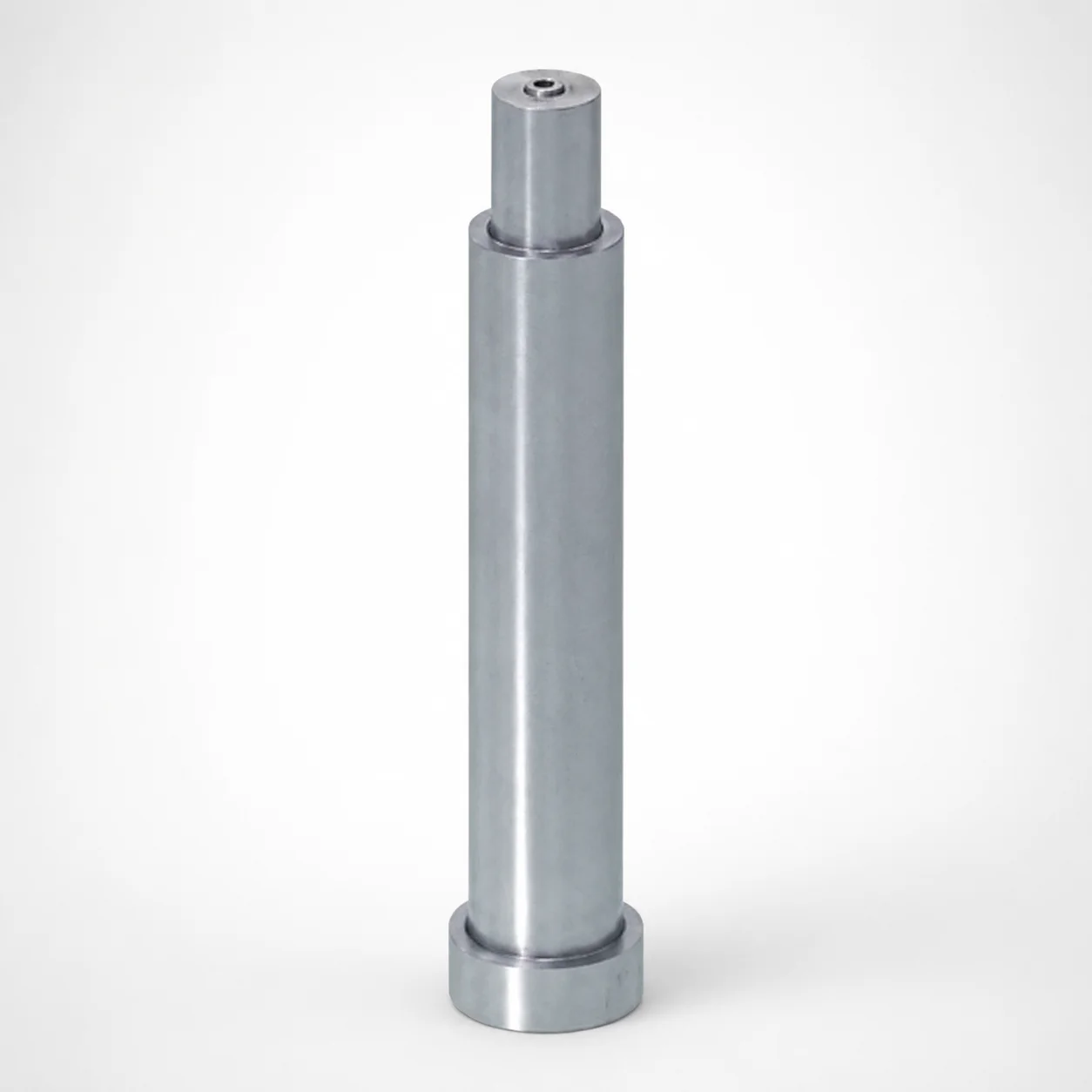
SKH51 Steel Pin-Point Gate Bushings with Head
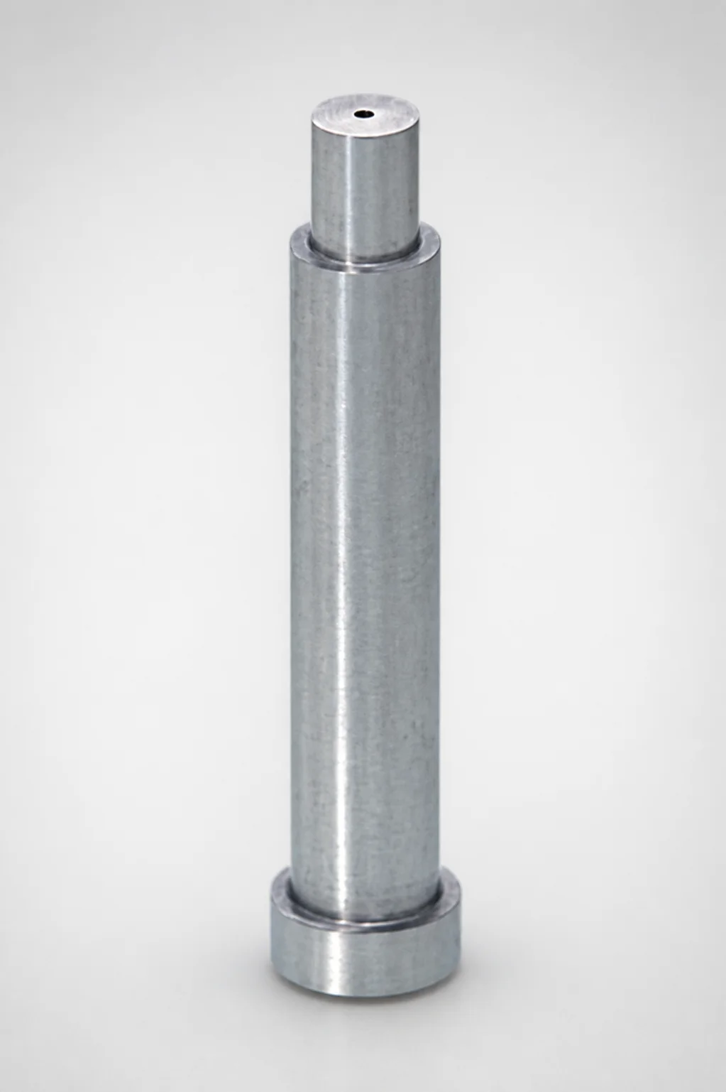
JIS Standard SKH51 Steel Pin-Point Gate Bushings (PGHTBL) with Head
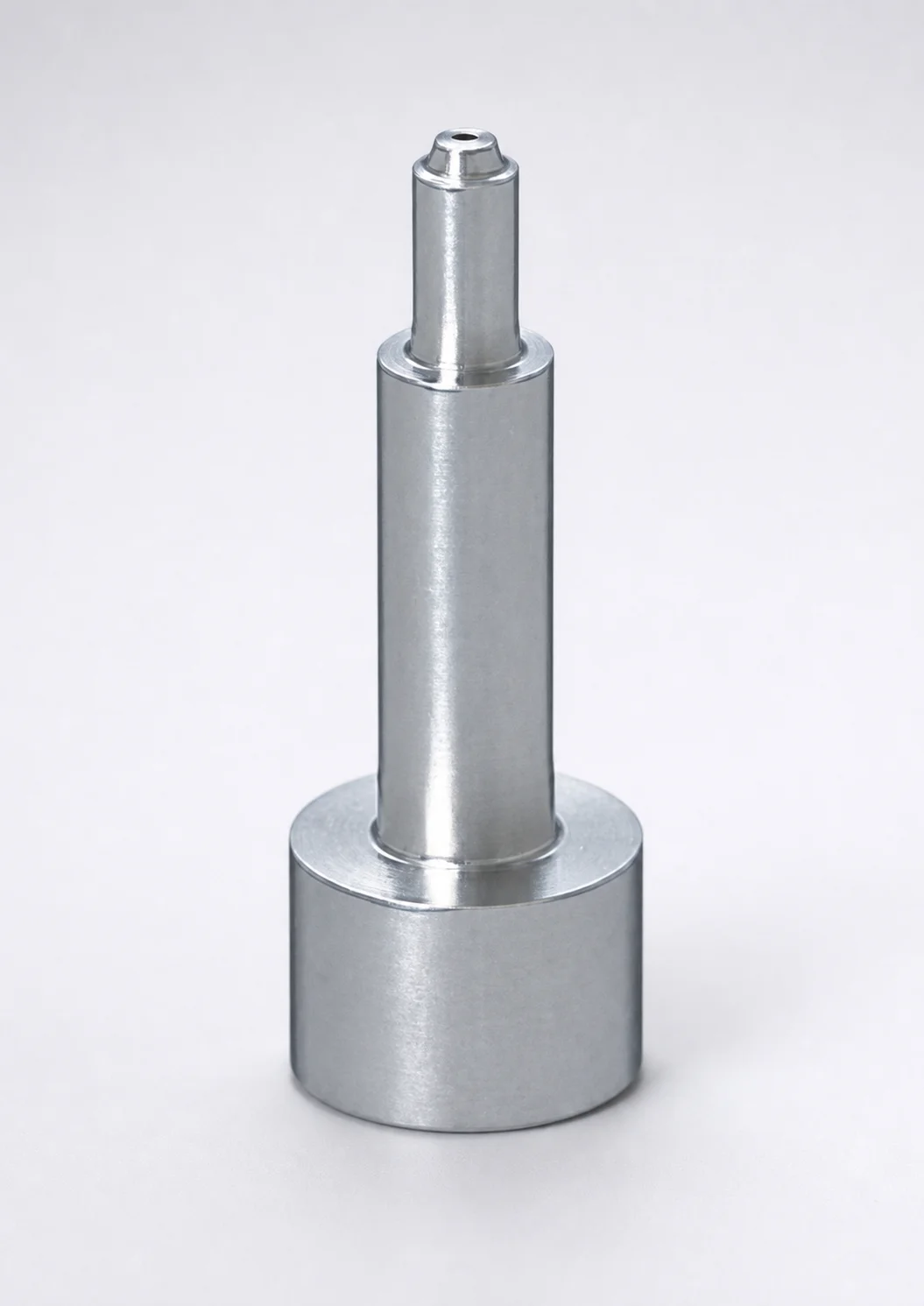
SKH51 Steel Pin-Point Gate Bushings with Head - Round Gate Transition
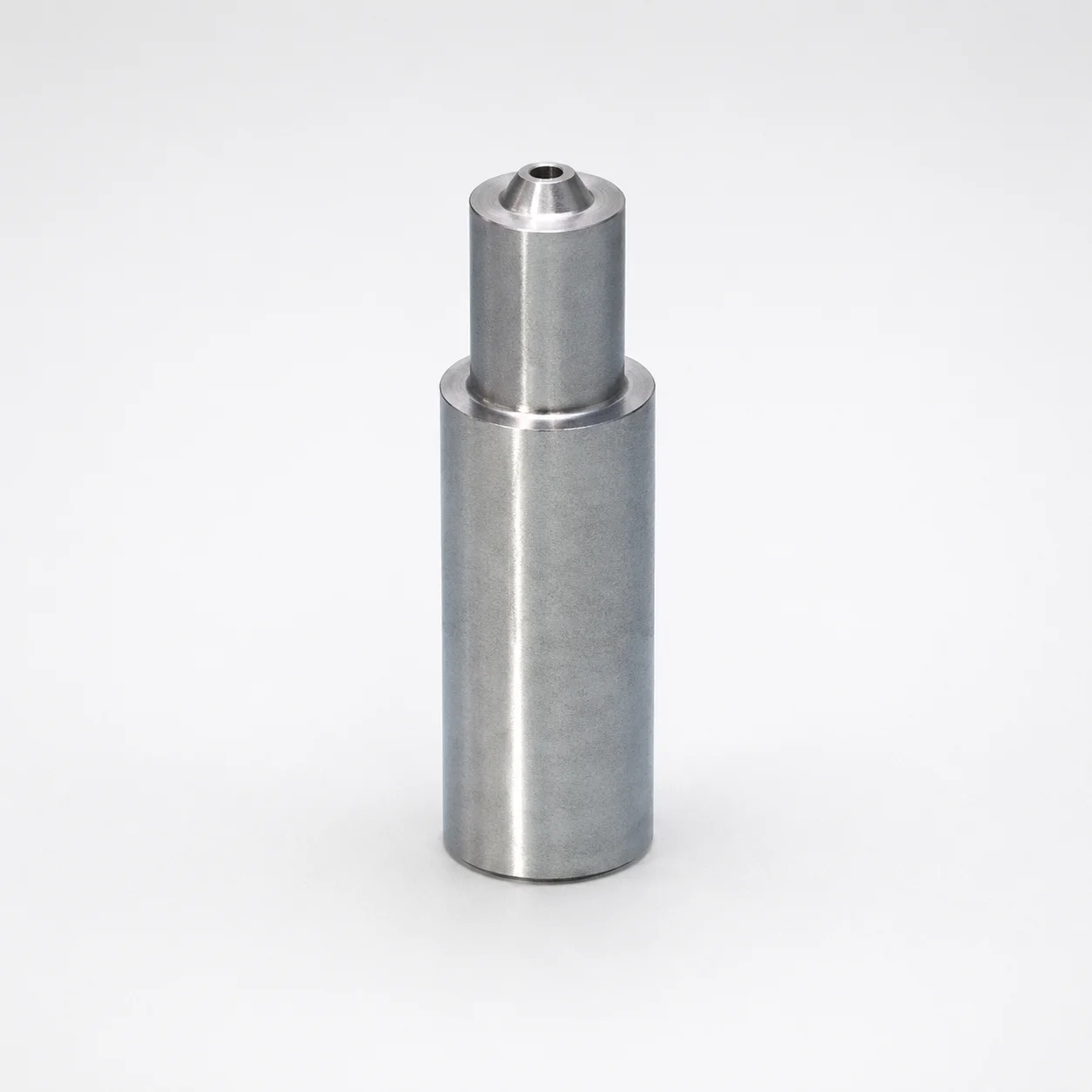
SKH51 Steel Pin-Point Gate Bushings Round Gate Transition SR
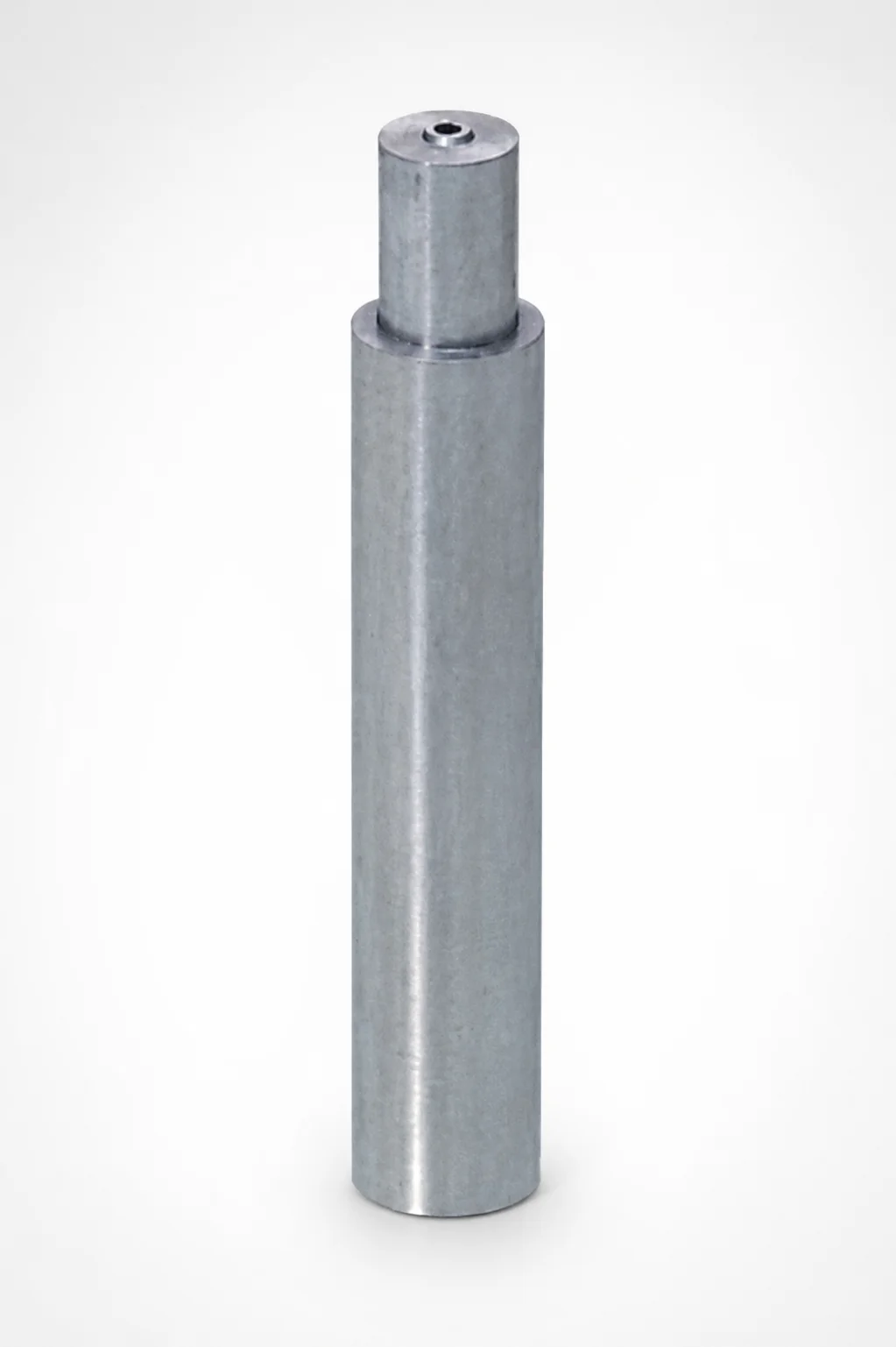
JIS Standard SKH51 Steel Pin-Point Gate Bushings Round Gate Transition SR
Need Custom Specifications?
Our engineering team can help with custom configurations, material selection, and volume pricing.