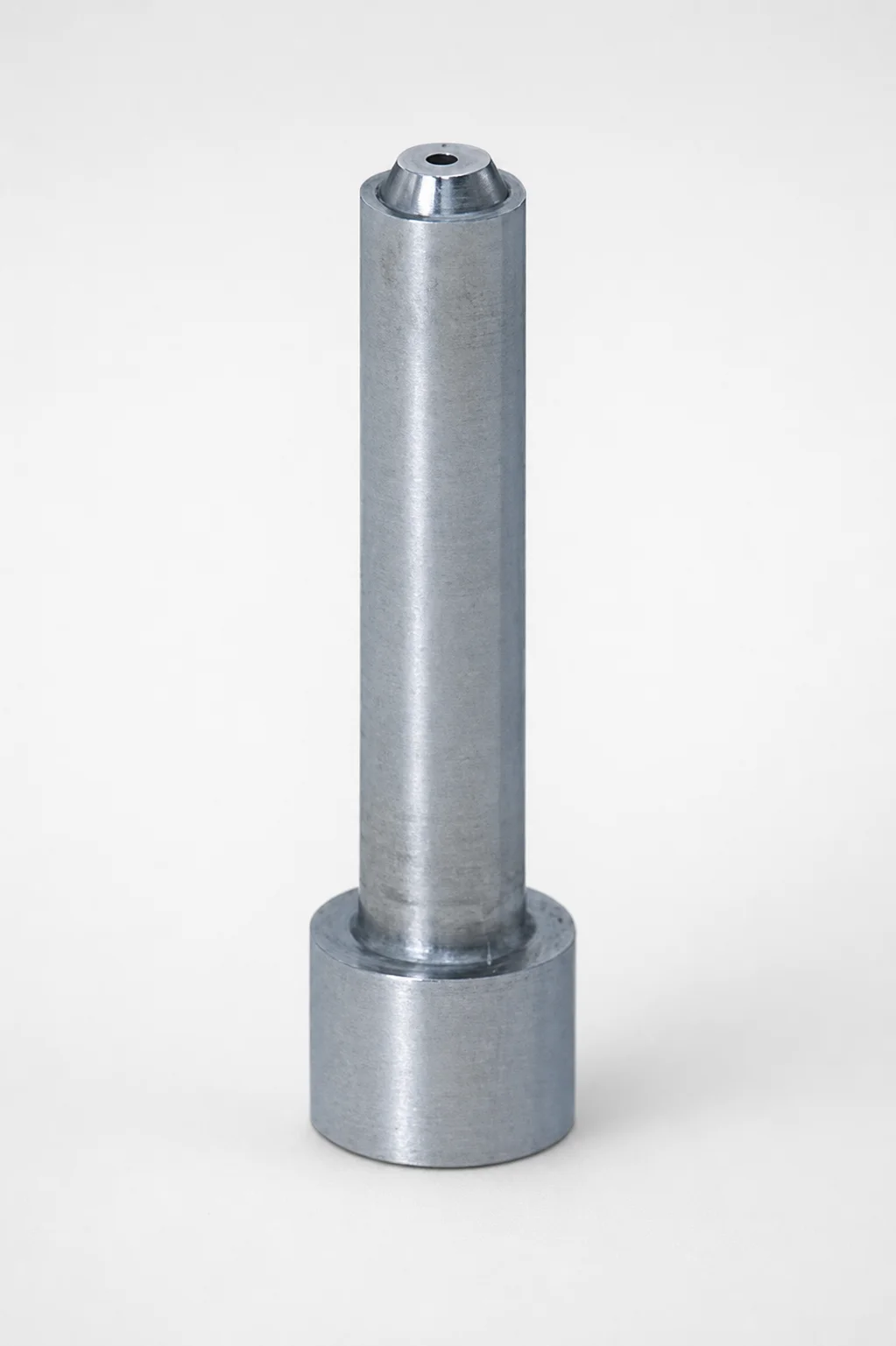
SKH51 Steel Pin-Point Gate Bushings - Round Gate Transition
Pin-Point Gate Bushings (SKH51 steel) with a round gate transition are designed to guide molten material from the sprue into the cavity with controlled pin-point gating. The SR tip step geometry helps maintain consistent flow while reducing stress at gate entry.
- Round gate transition supports smooth flow and stable pin-point gating during molding
- SKH51 hardened steel construction delivers wear resistance for repeat production cycles
- Tight P dimension tolerance ±0.01 helps achieve reliable positioning in the mold gate area
- Built for use in precision injection mold systems where consistent gate formation matters
Specifications
56 configurations available
| Tip Type | Tip Shape | P Dimension Tolerance | Tip Straight Tolerance | D (Outer diameter) (mm) | A (Taper angle) (°) | B (Length excluding the lengths of head and tip) (mm) | C (Tip length) (mm) | K (Cutting angle) (°) | L (L dimension) (mm) | P (Tip diameter) (mm) | R (Tip R) (mm) | S (Tip angle) (°) | V (Tip diameter) (mm) | type |
|---|---|---|---|---|---|---|---|---|---|---|---|---|---|---|
| Normal | 1A | ±0.01 | 0 to 0.2 | 2 | 1 ~ 3 | 3 ~ 5 | 0.2 ~ 0.4 | 20 ~ 30 | 6 ~ 20 | 0.3 ~ 0.5 | - | - | 1.3 ~ 1.9 | - |
| Normal | 1A | ±0.01 | 0 to 0.2 | 2.5 | 1 ~ 3 | 4 ~ 6 | 0.2 ~ 0.5 | 20 ~ 30 | 8 ~ 25 | 0.3 ~ 0.6 | - | - | 1.5 ~ 2.4 | - |
| Normal | 1A | ±0.01 | 0 to 0.2 | 3 | 1 ~ 3 | 5 ~ 9 | 0.3 ~ 0.8 | 20 ~ 30 | 10 ~ 40 | 0.5 ~ 0.9 | - | - | 2 ~ 2.9 | - |
| Normal | 1A | ±0.01 | 0 to 0.2 | 4 | 1 ~ 3 | 5 ~ 30 | 0.3 ~ 0.8 | 20 ~ 30 | 10 ~ 40 | 0.6 ~ 1.2 | - | - | 2.5 ~ 3.9 | - |
| Normal | 1A | ±0.01 | 0 to 0.2 | 5 | 1 ~ 3 | 5 ~ 35 | 0.5 ~ 1.5 | 20 ~ 30 | 15 ~ 60 | 0.8 ~ 1.5 | - | - | 3.5 ~ 4.9 | - |
| Normal | 1A | ±0.01 | 0 to 0.2 | 6 | 1 ~ 3 | 5 ~ 50 | 0.5 ~ 1.5 | 20 ~ 30 | 15 ~ 60 | 1 ~ 1.6 | - | - | 4 ~ 5.9 | - |
| Normal | 1A | ±0.01 | 0 to 0.2 | 8 | 1 ~ 3 | 5 ~ 50 | 0.5 ~ 1.5 | 20 ~ 30 | 15 ~ 60 | 1.2 ~ 1.6 | - | - | 4.5 ~ 7.9 | - |
| Normal | 2A | ±0.01 | 0 to 0.2 | 2 | 1 ~ 3 | 3 ~ 5 | - | 20 ~ 30 | 6 ~ 20 | 0.3 ~ 0.5 | - | - | - | - |
| Normal | 2A | ±0.01 | 0 to 0.2 | 2.5 | 1 ~ 3 | 4 ~ 6 | - | 20 ~ 30 | 8 ~ 25 | 0.3 ~ 0.6 | - | - | - | - |
| Normal | 2A | ±0.01 | 0 to 0.2 | 3 | 1 ~ 3 | 5 ~ 9 | - | 20 ~ 30 | 10 ~ 40 | 0.5 ~ 0.9 | - | - | - | - |
| Normal | 2A | ±0.01 | 0 to 0.2 | 4 | 1 ~ 3 | 5 ~ 30 | - | 20 ~ 30 | 10 ~ 40 | 0.6 ~ 1.2 | - | - | - | - |
| Normal | 2A | ±0.01 | 0 to 0.2 | 5 | 1 ~ 3 | 5 ~ 35 | - | 20 ~ 30 | 15 ~ 60 | 0.8 ~ 1.5 | - | - | - | - |
| Normal | 2A | ±0.01 | 0 to 0.2 | 6 | 1 ~ 3 | 5 ~ 50 | - | 20 ~ 30 | 15 ~ 60 | 1 ~ 1.6 | - | - | - | - |
| Normal | 2A | ±0.01 | 0 to 0.2 | 8 | 1 ~ 3 | 5 ~ 50 | - | 20 ~ 30 | 15 ~ 60 | 1.2 ~ 1.6 | - | - | - | - |
| Normal | 3A | ±0.01 | 0 to 0.2 | 2 | 1 ~ 3 | 3 ~ 5 | 0.2 ~ 0.4 | 20 ~ 30 | 6 ~ 20 | 0.3 ~ 0.5 | - | 1 ~ 45 | - | - |
| Normal | 3A | ±0.01 | 0 to 0.2 | 2.5 | 1 ~ 3 | 4 ~ 6 | 0.2 ~ 0.5 | 20 ~ 30 | 8 ~ 25 | 0.3 ~ 0.6 | - | 1 ~ 45 | - | - |
| Normal | 3A | ±0.01 | 0 to 0.2 | 3 | 1 ~ 3 | 5 ~ 9 | 0.3 ~ 0.8 | 20 ~ 30 | 10 ~ 40 | 0.5 ~ 0.9 | - | 1 ~ 45 | - | - |
| Normal | 3A | ±0.01 | 0 to 0.2 | 4 | 1 ~ 3 | 5 ~ 30 | 0.3 ~ 0.8 | 20 ~ 30 | 10 ~ 40 | 0.6 ~ 1.2 | - | 1 ~ 45 | - | - |
| Normal | 3A | ±0.01 | 0 to 0.2 | 5 | 1 ~ 3 | 5 ~ 35 | 0.5 ~ 1.5 | 20 ~ 30 | 15 ~ 60 | 0.8 ~ 1.5 | - | 1 ~ 45 | - | - |
| Normal | 3A | ±0.01 | 0 to 0.2 | 6 | 1 ~ 3 | 5 ~ 50 | 0.5 ~ 1.5 | 20 ~ 30 | 15 ~ 60 | 1 ~ 1.6 | - | 1 ~ 50 | - | - |
| Normal | 3A | ±0.01 | 0 to 0.2 | 8 | 1 ~ 3 | 5 ~ 50 | 0.5 ~ 1.5 | 20 ~ 30 | 15 ~ 60 | 1.2 ~ 1.6 | - | 1 ~ 60 | - | - |
| Normal | 4A | ±0.01 | 0 to 0.2 | 2 | 1 ~ 3 | 3 ~ 5 | 0.2 ~ 0.4 | 20 ~ 30 | 6 ~ 20 | 0.3 ~ 0.5 | 0.4 ~ 0.8 | - | - | - |
| Normal | 4A | ±0.01 | 0 to 0.2 | 2.5 | 1 ~ 3 | 4 ~ 6 | 0.2 ~ 0.5 | 20 ~ 30 | 8 ~ 25 | 0.3 ~ 0.6 | 0.6 ~ 1 | - | - | - |
| Normal | 4A | ±0.01 | 0 to 0.2 | 3 | 1 ~ 3 | 5 ~ 9 | 0.3 ~ 0.8 | 20 ~ 30 | 10 ~ 40 | 0.5 ~ 0.9 | 0.8 ~ 1.5 | - | - | - |
| Normal | 4A | ±0.01 | 0 to 0.2 | 4 | 1 ~ 3 | 5 ~ 30 | 0.3 ~ 0.8 | 20 ~ 30 | 10 ~ 40 | 0.6 ~ 1.2 | 0.8 ~ 1.5 | - | - | - |
| Normal | 4A | ±0.01 | 0 to 0.2 | 5 | 1 ~ 3 | 5 ~ 35 | 0.5 ~ 1.5 | 20 ~ 30 | 15 ~ 60 | 0.8 ~ 1.5 | 1 ~ 2 | - | - | - |
| Normal | 4A | ±0.01 | 0 to 0.2 | 6 | 1 ~ 3 | 5 ~ 50 | 0.5 ~ 1.5 | 20 ~ 30 | 15 ~ 60 | 1 ~ 1.6 | 1.5 ~ 3 | - | - | - |
| Normal | 4A | ±0.01 | 0 to 0.2 | 8 | 1 ~ 3 | 5 ~ 50 | 0.5 ~ 1.5 | 20 ~ 30 | 15 ~ 60 | 1.2 ~ 1.6 | 2 ~ 4 | - | - | - |
| Normal | 5A | ±0.01 | 0 to 0.2 | 2 | 1 ~ 3 | 3 ~ 5 | 0.2 ~ 0.4 | 20 ~ 30 | 6 ~ 20 | 0.3 ~ 0.5 | - | - | - | - |
| Normal | 5A | ±0.01 | 0 to 0.2 | 2.5 | 1 ~ 3 | 4 ~ 6 | 0.2 ~ 0.5 | 20 ~ 30 | 8 ~ 25 | 0.3 ~ 0.6 | - | - | - | - |
| Normal | 5A | ±0.01 | 0 to 0.2 | 3 | 1 ~ 3 | 5 ~ 9 | 0.3 ~ 0.8 | 20 ~ 30 | 10 ~ 40 | 0.5 ~ 0.9 | - | - | - | - |
| Normal | 5A | ±0.01 | 0 to 0.2 | 4 | 1 ~ 3 | 5 ~ 30 | 0.3 ~ 0.8 | 20 ~ 30 | 10 ~ 40 | 0.6 ~ 1.2 | - | - | - | - |
| Normal | 5A | ±0.01 | 0 to 0.2 | 5 | 1 ~ 3 | 5 ~ 35 | 0.5 ~ 1.5 | 20 ~ 30 | 15 ~ 60 | 0.8 ~ 1.5 | - | - | - | - |
| Normal | 5A | ±0.01 | 0 to 0.2 | 6 | 1 ~ 3 | 5 ~ 50 | 0.5 ~ 1.5 | 20 ~ 30 | 15 ~ 60 | 1 ~ 1.6 | - | - | - | - |
| Normal | 5A | ±0.01 | 0 to 0.2 | 8 | 1 ~ 3 | 5 ~ 50 | 0.5 ~ 1.5 | 20 ~ 30 | 15 ~ 60 | 1.2 ~ 1.6 | - | - | - | - |
| Acute angle | 1A | - | 0 to 0.05 | 2 | 1 ~ 3 | 3 ~ 5 | 0.2 ~ 0.4 | 20 ~ 30 | 6 ~ 20 | 0.3 ~ 0.5 | - | - | 1.3 ~ 1.9 | - |
| Acute angle | 1A | - | 0 to 0.05 | 2.5 | 1 ~ 3 | 4 ~ 6 | 0.2 ~ 0.5 | 20 ~ 30 | 8 ~ 25 | 0.3 ~ 0.6 | - | - | 1.5 ~ 2.4 | - |
| Acute angle | 1A | - | 0 to 0.05 | 3 | 1 ~ 3 | 5 ~ 9 | 0.3 ~ 0.8 | 20 ~ 30 | 10 ~ 40 | 0.5 ~ 0.9 | - | - | 2 ~ 2.9 | - |
| Acute angle | 1A | - | 0 to 0.05 | 4 | 1 ~ 3 | 5 ~ 30 | 0.3 ~ 0.8 | 20 ~ 30 | 10 ~ 40 | 0.6 ~ 1.2 | - | - | 2.5 ~ 3.9 | - |
| Acute angle | 1A | - | 0 to 0.05 | 5 | 1 ~ 3 | 5 ~ 35 | 0.5 ~ 1.5 | 20 ~ 30 | 15 ~ 60 | 0.8 ~ 1.5 | - | - | 3.5 ~ 4.9 | - |
| Acute angle | 1A | - | 0 to 0.05 | 6 | 1 ~ 3 | 5 ~ 50 | 0.5 ~ 1.5 | 20 ~ 30 | 15 ~ 60 | 1 ~ 1.6 | - | - | 4 ~ 5.9 | - |
| Acute angle | 1A | - | 0 to 0.05 | 8 | 1 ~ 3 | 5 ~ 50 | 0.5 ~ 1.5 | 20 ~ 30 | 15 ~ 60 | 1.2 ~ 1.6 | - | - | 4.5 ~ 7.9 | - |
| Acute angle | 2A | - | 0 to 0.05 | 2 | 1 ~ 3 | 3 ~ 5 | - | 20 ~ 30 | 6 ~ 20 | 0.3 ~ 0.5 | - | - | - | - |
| Acute angle | 2A | - | 0 to 0.05 | 2.5 | 1 ~ 3 | 4 ~ 6 | - | 20 ~ 30 | 8 ~ 25 | 0.3 ~ 0.6 | - | - | - | - |
| Acute angle | 2A | - | 0 to 0.05 | 3 | 1 ~ 3 | 5 ~ 9 | - | 20 ~ 30 | 10 ~ 40 | 0.5 ~ 0.9 | - | - | - | - |
| Acute angle | 2A | - | 0 to 0.05 | 4 | 1 ~ 3 | 5 ~ 30 | - | 20 ~ 30 | 10 ~ 40 | 0.6 ~ 1.2 | - | - | - | - |
| Acute angle | 2A | - | 0 to 0.05 | 5 | 1 ~ 3 | 5 ~ 35 | - | 20 ~ 30 | 15 ~ 60 | 0.8 ~ 1.5 | - | - | - | - |
| Acute angle | 2A | - | 0 to 0.05 | 6 | 1 ~ 3 | 5 ~ 50 | - | 20 ~ 30 | 15 ~ 60 | 1 ~ 1.6 | - | - | - | - |
| Acute angle | 2A | - | 0 to 0.05 | 8 | 1 ~ 3 | 5 ~ 50 | - | 20 ~ 30 | 15 ~ 60 | 1.2 ~ 1.6 | - | - | - | - |
| Acute angle | 3A | - | 0 to 0.05 | 2 | 1 ~ 3 | 3 ~ 5 | 0.2 ~ 0.4 | 20 ~ 30 | 6 ~ 20 | 0.3 ~ 0.5 | - | 1 ~ 45 | - | - |
Product Guide
Application Scenarios+
Pin-point gate bushings made from SKH51 are used at the transition between the sprue and cavity to produce a controlled, repeatable gate. The round gate transition variant helps stabilize molten flow as it concentrates into a small gate opening, which is critical for parts that require consistent knit-line behavior and clean gate appearance.
- Automotive connector and sensor housing molds: Use these bushings to maintain precise gate formation and reduce localized wear at the gate area through hardened steel, supporting long-run production.
- Medical device housings with tight cosmetic requirements: The controlled pin-point geometry supports smooth flow into fine features, improving the likelihood of stable part-to-part gate quality.
- High-precision consumer electronics enclosures: The tight P dimension tolerance ±0.01 supports accurate positioning for reliable assembly in precision gate systems.
Material & Process Details+
SKH51 steel pin-point gate bushings are designed for gate-area durability and dimensional stability in injection tooling. SKH51 is an equivalent of AISI M2 high-speed steel, known for high hardness and strong wear resistance under cyclic thermal and mechanical loading.
- Hardness & wear vs. toughness: In typical mold tooling usage, SKH51 is expected to be hardened to a high hardness level (often in the high-HRC range) for wear resistance at the gate tip. This high hardness improves resistance to erosion, while requiring attention to toughness trade-offs compared with lower-alloy steels.
- Heat treatment state: These bushings are supplied in a hardened condition suitable for precision gate formation; post-processing typically focuses on dimensional stability and surface finishing rather than re-hardening.
If you need higher impact toughness, consider alternative mold steels, but you would generally give up some gate-tip wear resistance relative to SKH51.
Sizing & Selection Guide+
Select the bushing size by matching the gate tip dimensions and overall geometry to your mold cavity/core gate requirements. Start with the shaft/tip diameter P (given as 0.3 to 1.2 mm) to define the actual pin-point gate opening controlled at the cavity interface.
- Outer diameter D: Choose D = 2 to 8 mm so the bushing fits the corresponding bore in the sprue/gate insert or guide block.
- Length matching (B and L): Confirm the stack-up length using B = 3 to 5, 4 to 6, 5 to 9, 5 to 30, 5 to 35, 5 to 50 mm (length excluding head and tip) and L = 6 to 20, 8 to 25, 10 to 40, 15 to 60 mm (overall L dimension range per configuration).
- Tip geometry: Use C (tip length), R (tip radius), and taper angle A = 1° to 3° to align the round gate transition profile to your gate land design.
Because P tolerance is ±0.01, use that value when checking gate opening targets and assembly fit around the gate bushing to ensure stable pin-point gating.
Frequently Asked Questions
How do I choose the correct tip diameter (P) for stable pin-point gating?+
The pin-point gate opening is defined by the P (tip diameter) dimension, available in the range 0.3 to 1.2 mm. Keep in mind the P dimension tolerance ±0.01, which helps ensure consistent bushing-to-gate positioning in precision mold assemblies. Match P to the cavity gate opening target to avoid unintended gate size variation.
Which dimensions control the round gate transition profile at the cavity entry?+
The round gate transition is governed by the tip geometry: C (tip length), R (tip radius), and the taper angle A = 1° to 3°. Select C within 0.2 to 1.5 mm (depending on the configuration) and R within the provided ranges (e.g., 0.4 to 0.8 mm, 1 to 2 mm, or 2 to 4 mm) to match your gate land and flow transition design.
What outer diameter (D) should I use to ensure the bushing fits the mold bore?+
Choose D (outer diameter) within 2 to 8 mm based on the bore size in your sprue/gate insert or guide block. Because assembly alignment strongly affects gate formation consistency, verify that the selected D configuration also supports the required length stack-up using B and L ranges. Confirm fit with your local tolerancing strategy for the mold insert.
How do I select between normal and acute angle tip types for my gating strategy?+
This series supports Tip Type: Normal or Acute angle. Use the acute-angle option when you need a geometry that promotes more directed entry behavior at the gate, while selecting the normal option for more conventional transition behavior. Pair the tip type selection with the appropriate taper angle A (1° to 3°) and tip straight tolerance target for your mold requirements.
What tolerance and positioning risks should I consider given tip straight tolerance options?+
The product lists Tip Straight Tolerance options of 0 to 0.2 and 0 to 0.05. For assemblies that demand tighter alignment at the gate entry, prefer the smaller tolerance option to reduce variation in how the pin-point tip meets the cavity gate zone. Also rely on the P ±0.01 tolerance to control gate diameter consistency.
Related Products
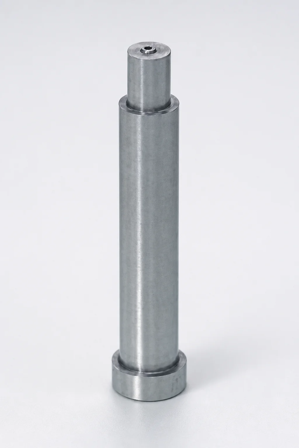
SKH51 Steel Pin-Point Gate Bushings with Head - Round Gate Transition (SR)
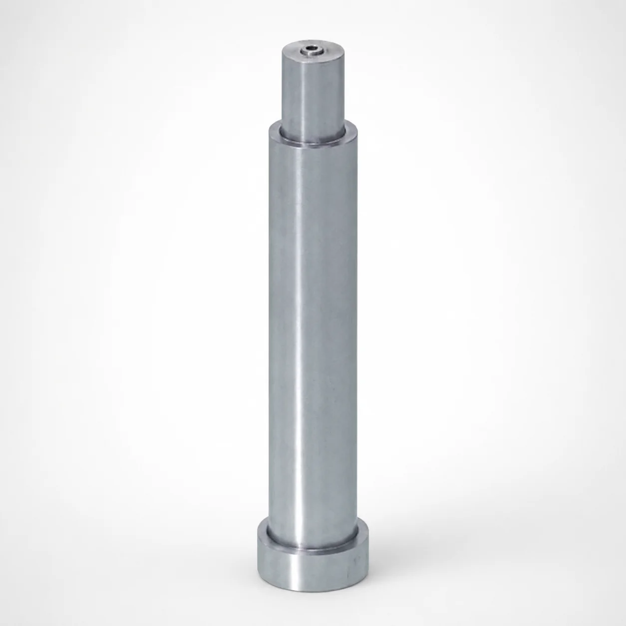
SKH51 Steel Pin-Point Gate Bushings with Head
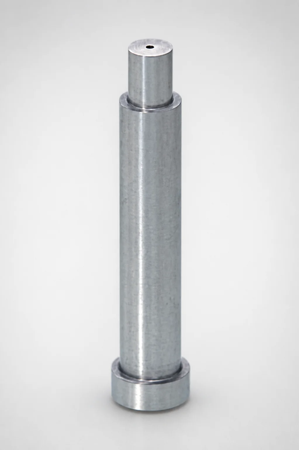
JIS Standard SKH51 Steel Pin-Point Gate Bushings (PGHTBL) with Head
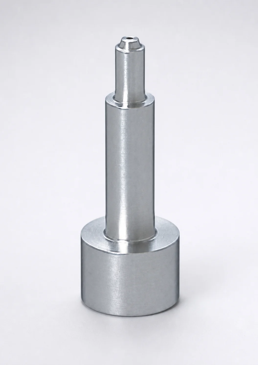
SKH51 Steel Pin-Point Gate Bushings with Head - Round Gate Transition
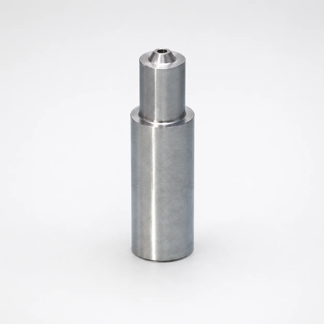
SKH51 Steel Pin-Point Gate Bushings Round Gate Transition SR
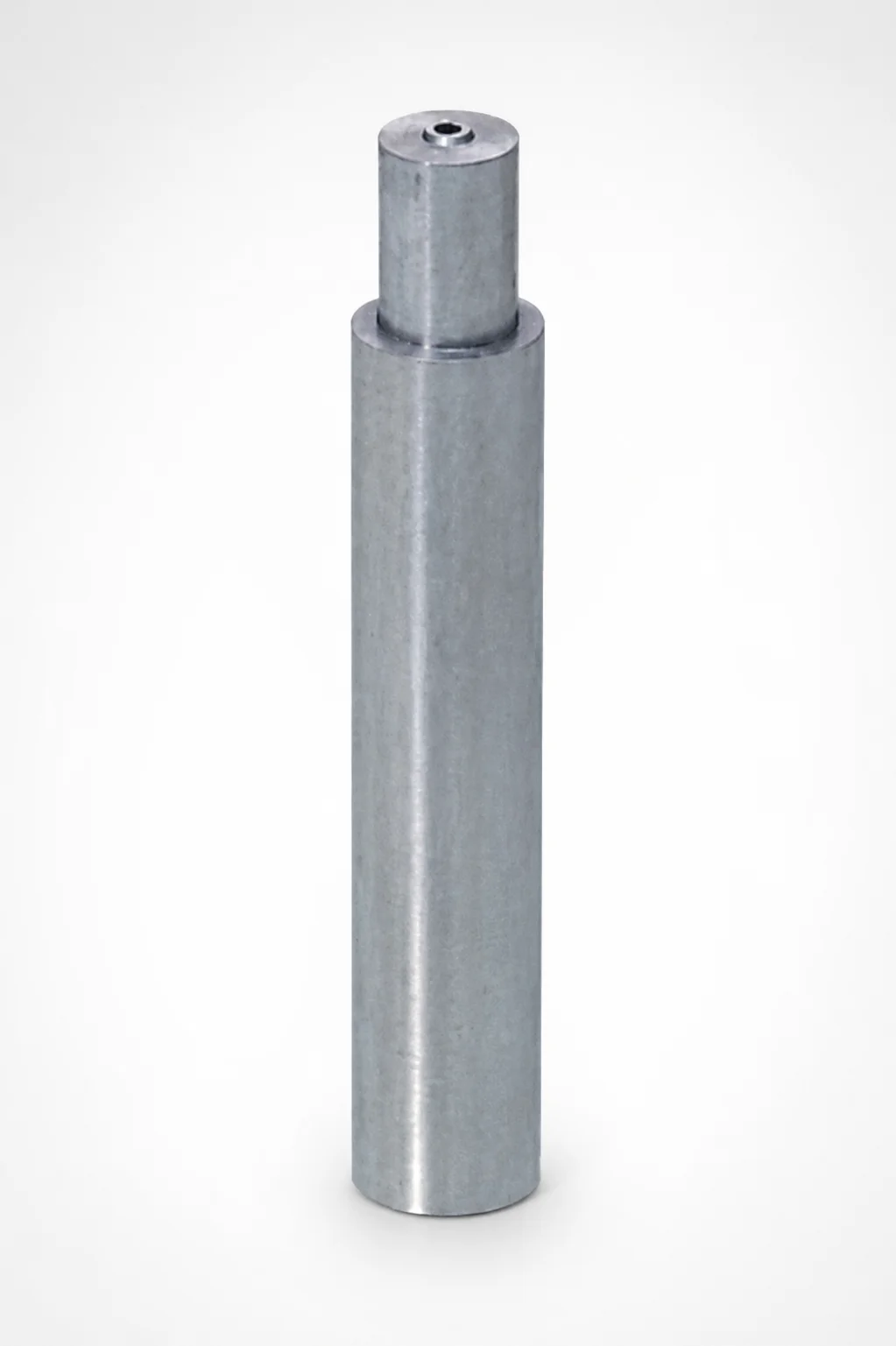
JIS Standard SKH51 Steel Pin-Point Gate Bushings Round Gate Transition SR
Need Custom Specifications?
Our engineering team can help with custom configurations, material selection, and volume pricing.