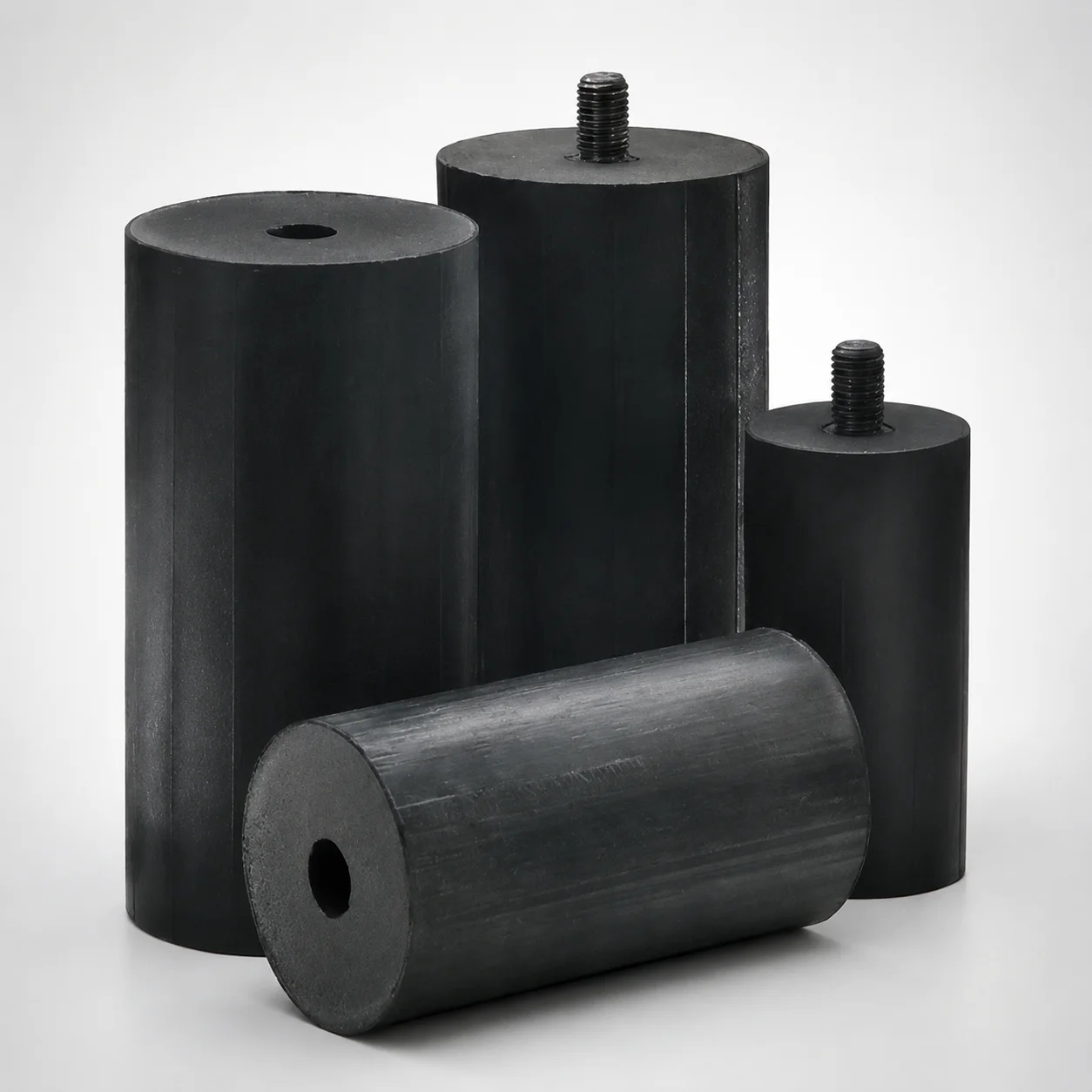
Marshmellow Die Springs Metric Urethane Springs
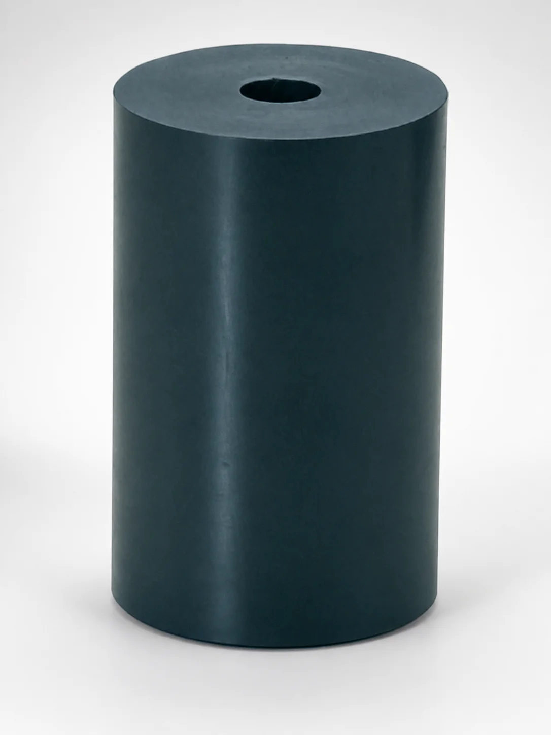
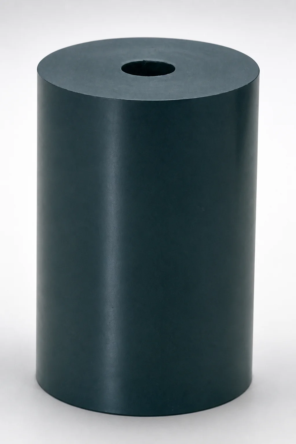
Marshmellow Die Springs Metric Urethane Springs (Lamina) are engineered for heavy-load support using a urethane body with Shore A 90 hardness. Their pillar shape and installed hole/counterbore geometry help achieve reliable positioning and durable performance in die systems.
- Pillar-formed urethane spring body built for robust load-bearing support.
- Urethane construction with Shore A 90 hardness for stable stiffness under load.
- Hole and counterbore design simplifies mounting and integration into die tooling.
- Metric die spring format for consistent fit within mold and press assembly layouts.
Specifications
88 configurations available
| Maximum Load (N) | Maximum Elongation (%) | Length (L) (mm) | Outside diameter (mm) | d (Inner diameter) (mm) | Locating Stud |
|---|---|---|---|---|---|
| 38 | 8.8 | 32 | 30 | 8 | without |
| 38 | 8.8 | 32 | 30 | 8 | with |
| 38 | 11 | 40 | 30 | 8 | without |
| 38 | 11 | 40 | 30 | 8 | with |
| 38 | 13.75 | 50 | 30 | 8 | without |
| 38 | 13.75 | 50 | 30 | 8 | with |
| 38 | 17.33 | 63 | 30 | 8 | without |
| 38 | 17.33 | 63 | 30 | 8 | with |
| 50 | 11 | 40 | 40 | 16 | without |
| 50 | 11 | 40 | 40 | 16 | with |
| 50 | 13.75 | 50 | 40 | 16 | without |
| 50 | 13.75 | 50 | 40 | 16 | with |
| 50 | 17.33 | 63 | 40 | 16 | without |
| 50 | 17.33 | 63 | 40 | 16 | with |
| 50 | 22 | 80 | 40 | 16 | without |
| 50 | 22 | 80 | 40 | 16 | with |
| 64 | 13.75 | 50 | 50 | 20 | without |
| 64 | 13.75 | 50 | 50 | 20 | with |
| 64 | 17.33 | 63 | 50 | 20 | without |
| 64 | 17.33 | 63 | 50 | 20 | with |
| 64 | 22 | 80 | 50 | 20 | without |
| 64 | 22 | 80 | 50 | 20 | with |
| 64 | 27.5 | 100 | 50 | 20 | without |
| 64 | 27.5 | 100 | 50 | 20 | with |
| 79 | 17.33 | 63 | 63 | 20 | without |
| 79 | 17.33 | 63 | 63 | 20 | with |
| 79 | 22 | 80 | 63 | 20 | without |
| 79 | 22 | 80 | 63 | 20 | with |
| 79 | 27.5 | 100 | 63 | 20 | without |
| 79 | 27.5 | 100 | 63 | 20 | with |
| 79 | 34.38 | 125 | 63 | 20 | without |
| 79 | 34.38 | 125 | 63 | 20 | with |
| 104 | 22 | 80 | 80 | 25 | without |
| 104 | 22 | 80 | 80 | 25 | with |
| 104 | 27.5 | 100 | 80 | 25 | without |
| 104 | 27.5 | 100 | 80 | 25 | with |
| 104 | 34.38 | 125 | 80 | 25 | without |
| 104 | 34.38 | 125 | 80 | 25 | with |
| 104 | 38.5 | 140 | 80 | 25 | without |
| 104 | 38.5 | 140 | 80 | 25 | with |
| 104 | 41.25 | 150 | 80 | 25 | without |
| 104 | 41.25 | 150 | 80 | 25 | with |
| 128 | 27.5 | 100 | 100 | 25 | without |
| 128 | 27.5 | 100 | 100 | 25 | with |
| 128 | 34.38 | 125 | 100 | 25 | without |
| 128 | 34.38 | 125 | 100 | 25 | with |
| 128 | 38.5 | 140 | 100 | 25 | without |
| 128 | 38.5 | 140 | 100 | 25 | with |
| 128 | 41.25 | 150 | 100 | 25 | without |
| 128 | 41.25 | 150 | 100 | 25 | with |
Product Guide
Application Scenarios+
These metric urethane die springs are used to provide controlled, repeatable force in injection mold tooling where safe support and stable die positioning matter. The pillar form and counterbore/installed-hole geometry support consistent alignment during press cycles, helping reduce drift in heavy-load assemblies.
- Automotive connector and bracket mold support: Use springs with higher capacity (within the 38–192 N maximum load range) to maintain contact force at the slide or die-set interfaces under long production runs.
- Consumer electronics housing tooling: The Shore A 90 stiffness supports predictable return and damping when elongation demands range up to 68.75%, improving part-to-part consistency.
- Packaging insert or thick-walled parts: Select the appropriate outside diameter (30–150 mm) and length (32–250 mm) to match available space and mounting features for reliable setup.
The urethane body is suited for applications needing stable stiffness with a simpler mounting interface (hole/counterbore), especially where mechanical springs alone may be less tolerant to assembly variation.
Material & Process Details+
This series uses a urethane spring body specified for Shore A 90 hardness, providing a balance of stiffness and damping for heavy-load die support. Urethane elastomers typically trade absolute rigidity for controlled compliance, which helps maintain stable force delivery across cyclic loading.
- Hardness: Shore A 90 is selected for consistent stiffness under load and repeatable spring response.
- Heat treatment: Urethane springs are manufactured as an elastomeric molded component; no steel-style quenching and tempering is specified in this variant.
- Wear resistance vs. toughness: Compared with softer urethane grades, Shore A 90 improves load-bearing stiffness, while still offering elastomer damping rather than brittle fracture behavior seen in hard metallic springs.
- Manufacturing approach: Pillar-formed urethane with integrated hole/counterbore is molded to geometry for stable setup and easier installation.
Sizing & Selection Guide+
Select dimensions by matching the spring’s load/deflection capability to the die-set requirement and then fitting it into the mold’s available space. Start with the needed force using the Maximum Load: 38–192 N range and confirm the expected movement does not exceed the Maximum Elongation: 8.8–68.75% for the selected size.
- Length (L): Choose within 32–250 mm so the installed height works with your press clearance and die opening/closing stroke.
- Outside diameter: Select 30–150 mm to fit the pocket/land area without interference with surrounding tooling.
- Inner diameter (d): Match the available locating/shaft feature using d options 8, 16, 20, 25 mm.
- Locating stud: Pick without or with based on whether your die-set uses the locating stud to control assembly repeatability.
For proper function, ensure the hole/counterbore interface seats fully and that the spring can compress along its axis without side loading.
Frequently Asked Questions
How do I choose the correct maximum load and elongation for these urethane die springs?+
Use the specified Maximum Load (N) range of 38–192 N to target the required support force in your die set. Then verify your expected compression/deflection does not exceed the Maximum Elongation (%) of 8.8–68.75% for the chosen length and diameter. If the required working movement is near the upper elongation limit, select a larger capacity size within the series.
Which inside diameter (d) options are available, and how do they affect compatibility with the mold locating features?+
This series provides inner diameter d options of 8, 16, 20, 25 mm. Select the d value that matches your die platen hole, locating shaft, or installed geometry so the spring aligns axially and avoids lateral stress during cycling.
How should I determine the spring length (L) for a given mold cavity/core space?+
Choose Length (L) from 32–250 mm to fit the available installed height in your die assembly. Confirm that the selected length allows proper clearance through opening/closing while still achieving the necessary preload/working stroke. If space is constrained, reduce L only after ensuring the load and elongation requirements remain within the specified ranges.
What is the role of the pillar form and counterbore/installed hole in die stability?+
The pillar-formed urethane body plus the hole/counterbore geometry is intended to support stable positioning during press cycles. This design helps maintain consistent placement and simplifies integration into tooling layouts by providing an engineered mounting interface.
When should I select a version 'with locating stud' versus 'without'?+
Choose with locating stud when your die-set design uses the locating stud to improve assembly repeatability and alignment. Choose without when your existing mold tooling already provides alignment through other features, or when you need a simpler interface compatible with your current mounting arrangement.
Related Products
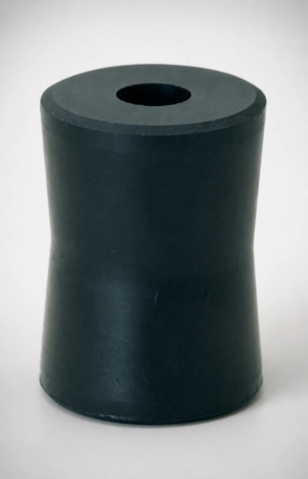
EX Series Heavy-Duty Urethane Pillar Springs (Through Hole)
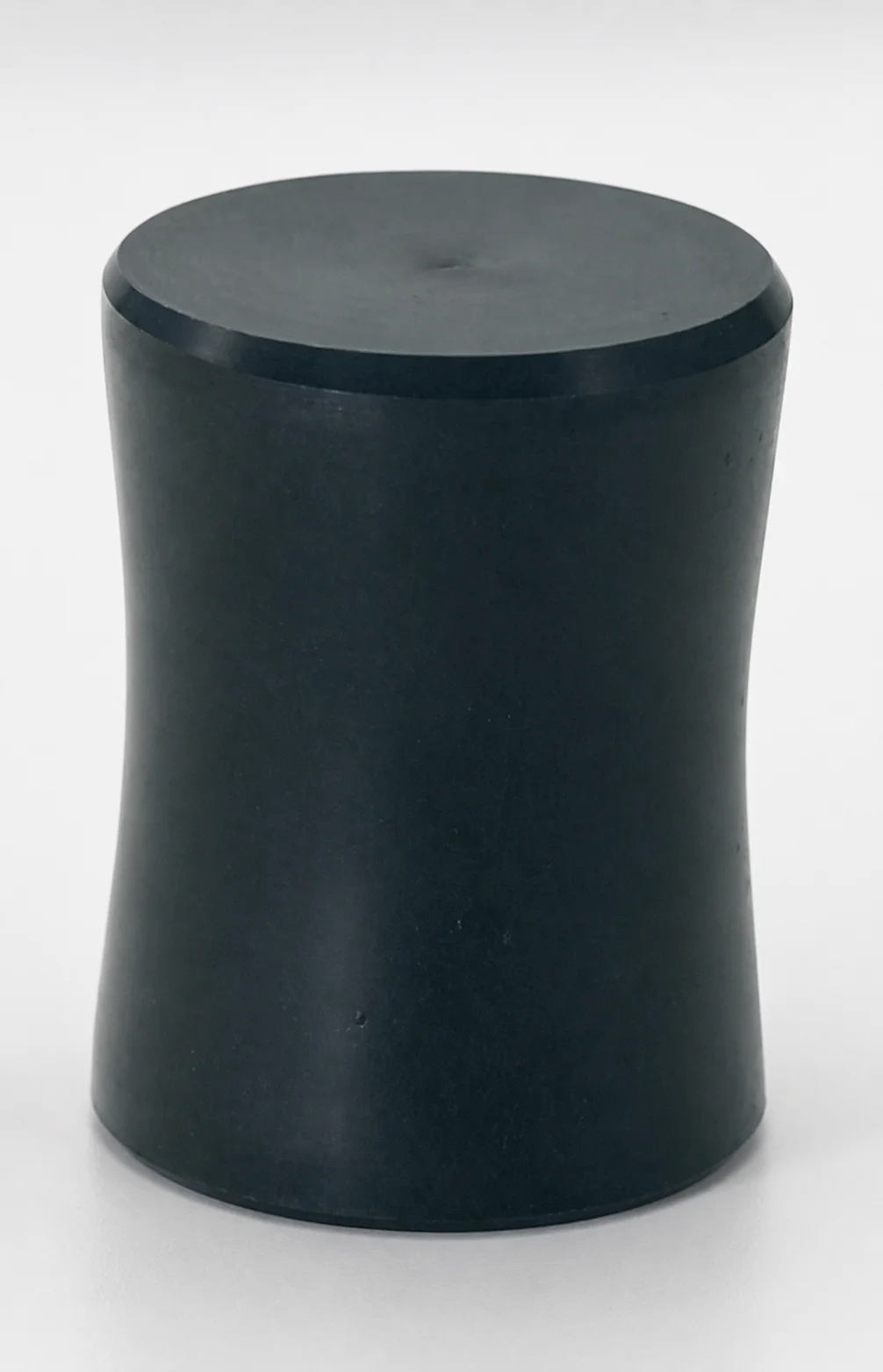
EX Series Heavy Duty Urethane Springs Pillar Hourglass
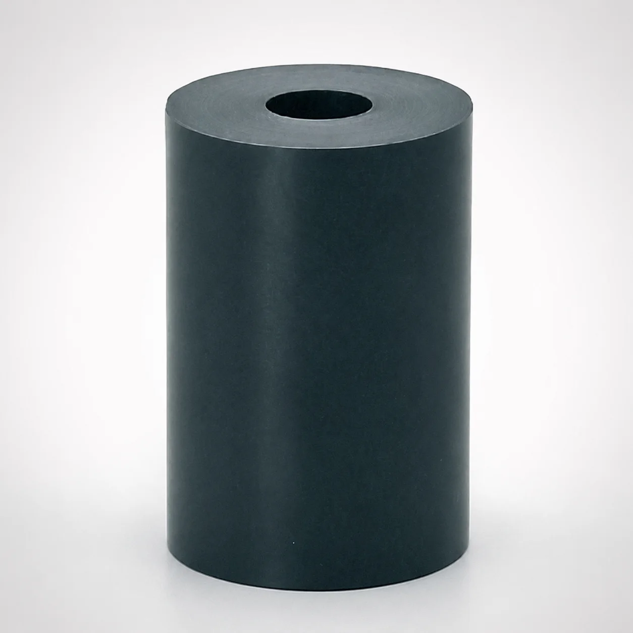
Heavy Duty Urethane Pillar Springs - A Series, Through Hole
E Series Heavy Duty Urethane Springs - Pillar Type Through Hole
EL Series Heavy Load Urethane Pillar Springs Through Hole
Heavy Duty Urethane Springs Pillar Shape
Need Custom Specifications?
Our engineering team can help with custom configurations, material selection, and volume pricing.