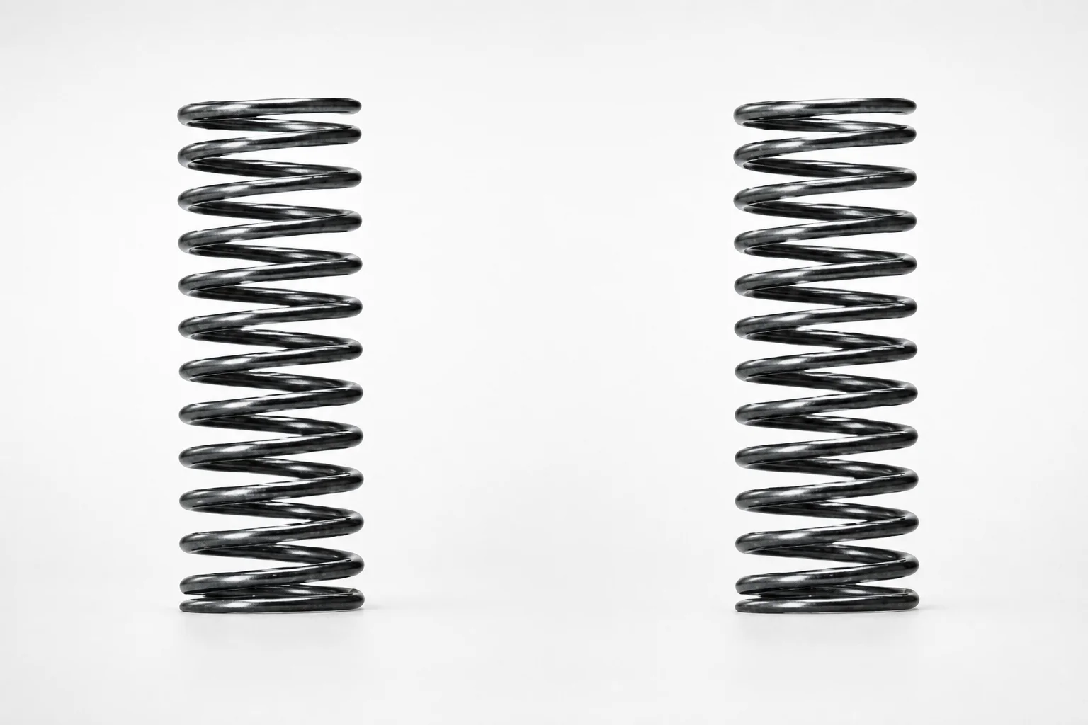
Round Wire Coil Springs - Inner Diameter Selection Type
Round Wire Coil Springs - Inner Diameter Selection Type deliver dependable support and controlled flexibility using round-wire construction. They help absorb shock, maintain consistent tension, and protect assemblies by reducing wear under repetitive mechanical loads.
- Inner diameter selection design supports consistent fit and stable spring alignment
- Round wire coil construction provides durable tension for reliable force transmission
- Configurable allowable deflection ratio and maximum load match varying operating conditions
- Built for demanding mechanical systems where efficient shock absorption matters
Specifications
64 configurations available
| Allowable Deflection Ratio (%) | Maximum Load (N) | Length L (mm) | Inner Diameter (mm) | type |
|---|---|---|---|---|
| 40 | 1.4 | 30 | 5.5 | - |
| 40 | 1.4 | 35 | 5.5 | - |
| 40 | 1.4 | 40 | 5.5 | - |
| 40 | 1.4 | 45 | 5.5 | - |
| 40 | 1.4 | 50 | 5.5 | - |
| 40 | 1.4 | 30 | 6.5 | - |
| 40 | 1.4 | 35 | 6.5 | - |
| 40 | 1.4 | 40 | 6.5 | - |
| 40 | 1.4 | 45 | 6.5 | - |
| 40 | 1.4 | 50 | 6.5 | - |
| 40 | 2.1 | 30 | 8.5 | - |
| 40 | 2.1 | 35 | 8.5 | - |
| 40 | 2.1 | 40 | 8.5 | - |
| 40 | 2.1 | 45 | 8.5 | - |
| 40 | 2.1 | 50 | 8.5 | - |
| 40 | 2.1 | 60 | 8.5 | - |
| 40 | 2.1 | 30 | 10.6 | - |
| 40 | 2.1 | 35 | 10.6 | - |
| 40 | 2.1 | 40 | 10.6 | - |
| 40 | 2.1 | 45 | 10.6 | - |
| 40 | 2.1 | 50 | 10.6 | - |
| 40 | 2.1 | 60 | 10.6 | - |
| 40 | 2.8 | 35 | 13.6 | - |
| 40 | 2.8 | 40 | 13.6 | - |
| 40 | 2.8 | 45 | 13.6 | - |
| 40 | 2.8 | 50 | 13.6 | - |
| 40 | 2.8 | 60 | 13.6 | - |
| 40 | 2.8 | 35 | 16.6 | - |
| 40 | 2.8 | 40 | 16.6 | - |
| 40 | 2.8 | 45 | 16.6 | - |
| 40 | 2.8 | 50 | 16.6 | - |
| 40 | 2.8 | 60 | 16.6 | - |
| 32 | 2.1 | 30 | 5.5 | - |
| 32 | 2.1 | 35 | 5.5 | - |
| 32 | 2.1 | 40 | 5.5 | - |
| 32 | 2.1 | 45 | 5.5 | - |
| 32 | 2.1 | 50 | 5.5 | - |
| 32 | 2.1 | 30 | 6.5 | - |
| 32 | 2.1 | 35 | 6.5 | - |
| 32 | 2.1 | 40 | 6.5 | - |
| 32 | 2.1 | 45 | 6.5 | - |
| 32 | 2.1 | 50 | 6.5 | - |
| 32 | 2.8 | 30 | 8.5 | - |
| 32 | 2.8 | 35 | 8.5 | - |
| 32 | 2.8 | 40 | 8.5 | - |
| 32 | 2.8 | 45 | 8.5 | - |
| 32 | 2.8 | 50 | 8.5 | - |
| 32 | 2.8 | 60 | 8.5 | - |
| 32 | 2.8 | 30 | 10.6 | - |
| 32 | 2.8 | 35 | 10.6 | - |
Product Guide
Application Scenarios+
Round-wire coil springs in injection mold tooling are used as compact mechanical energy-storage elements in places where vibration control and repeatable force matter. This inner-diameter-selection type is particularly suited to assemblies that require stable spring alignment and predictable restoring force over repeated cycling.
- Tooling shock absorption and ejector return assistance: Use selected inner diameters (e.g., 5.5–16.6 mm) and matched allowable deflection ratios (32% or 40%) to stabilize motion and reduce impact loads during frequent open/close and eject cycles.
- Automotive connector and sensor housings: In molds with frequent part handling interruptions, the spring’s controlled tension helps maintain consistent contact pressure and reduces wear at sliding interfaces.
- Medical device housing molds: When minimizing dimensional drift is critical, choosing a specific maximum load (1.4–3.5 N) supports stable force transmission without over-compressing the spring under tight assembly constraints.
By selecting the correct inner diameter and load/deflection limits, engineers can tailor force response to the mechanical system rather than relying on generic spring behavior.
Material & Process Details+
The provided product data does not specify a steel grade, hardness (HRC), or heat-treatment condition. Therefore, material-related properties such as wear resistance, toughness, and any quench/temper or nitriding state cannot be stated from the current specifications.
- Selection implication: For mold designs, the critical performance inputs available here are allowable deflection ratio (32% or 40%) and maximum load (1.4–3.5 N), which directly affect stress level and fatigue life under cycling.
- Trade-offs to verify: If you require higher wear resistance (typically linked with higher hardness) versus improved toughness (typically linked with lower hardness), confirm the steel grade and heat treatment from the full technical datasheet or supplier documentation.
Please provide the steel/material and hardness/heat-treatment details to enable an accurate materials engineering section for this component variant.
Sizing & Selection Guide+
Correct selection starts by matching the spring’s inner diameter to the guided feature in the mold assembly. This model uses an inner diameter selection type with available inner diameters of 5.5, 6.5, 8.5, 10.6, 13.6, and 16.6 mm, enabling stable alignment around a shaft or guide element.
- Step 1: Choose inner diameter (ID): Select the closest ID to your guiding shaft/center post so the spring seats correctly and avoids lateral shift.
- Step 2: Set stroke/deflection target: Use allowable deflection ratio of 32% or 40% to ensure the design compression stays within the supported operating range.
- Step 3: Match force requirement: Confirm maximum load at the required compression corresponds to your force budget: 1.4, 2.1, 2.8, or 3.5 N.
- Step 4: Select free length: Pick the spring length L = 30, 35, 40, 45, 50, or 60 mm to fit the available cavity space.
Check tolerance and fit at both the ID interface and the length stack-up (seat-to-seat distances). When ID is near a limit, choose a slightly larger ID to reduce binding risk, and validate with assembled compression calculations using the selected deflection ratio.
Frequently Asked Questions
How do I select the correct inner diameter for a guided spring application in a mold assembly?+
What does the allowable deflection ratio (32% vs 40%) mean for choosing spring travel in an injection tooling design?+
How do I choose between maximum load ratings (1.4, 2.1, 2.8, 3.5 N) when designing for return force?+
Which length (L = 30–60 mm) should I use to avoid coil bind in a constrained tool space?+
Can I combine any inner diameter with any length and load in this series, or are combinations restricted?+
Related Products
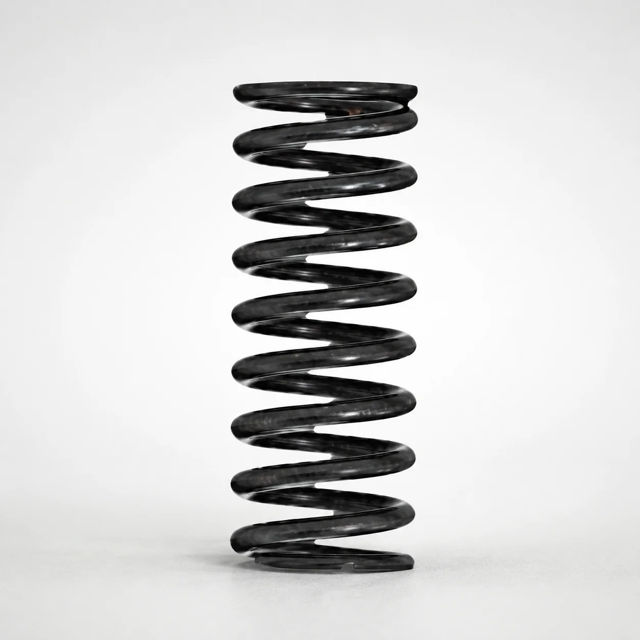
Round Wire Coil Springs - 75% Deflection, WY Series
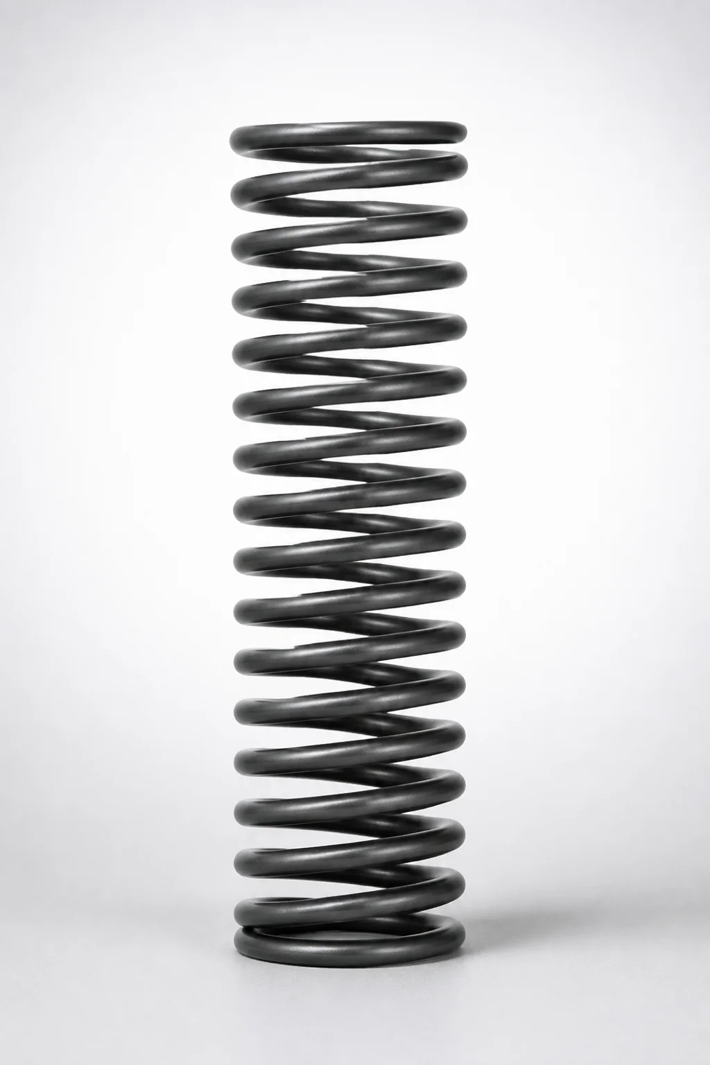
WR Series Round Wire Coil Springs 60% Deflection
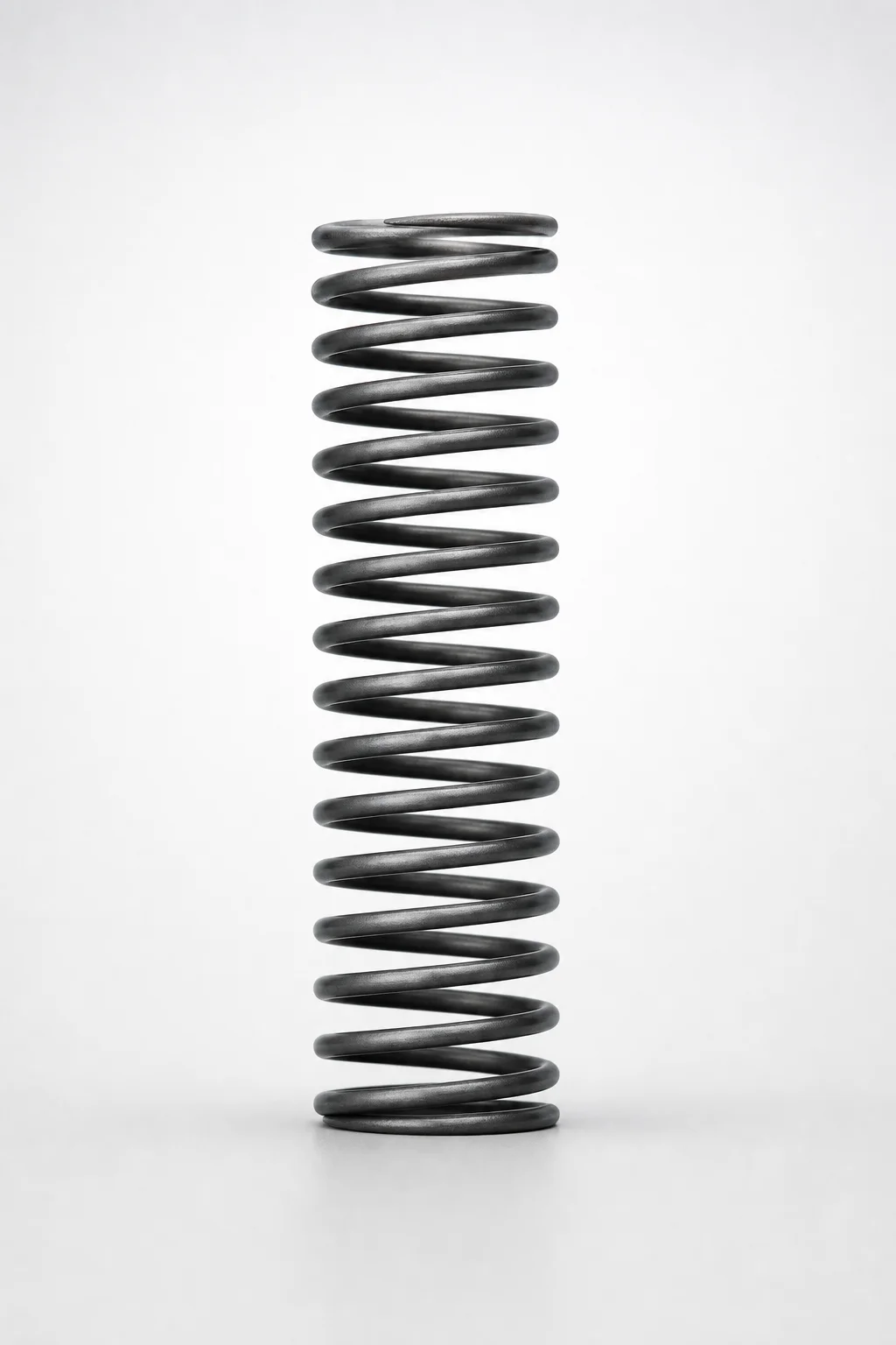
Round Wire Coil Springs - 45% Deflection WF Series
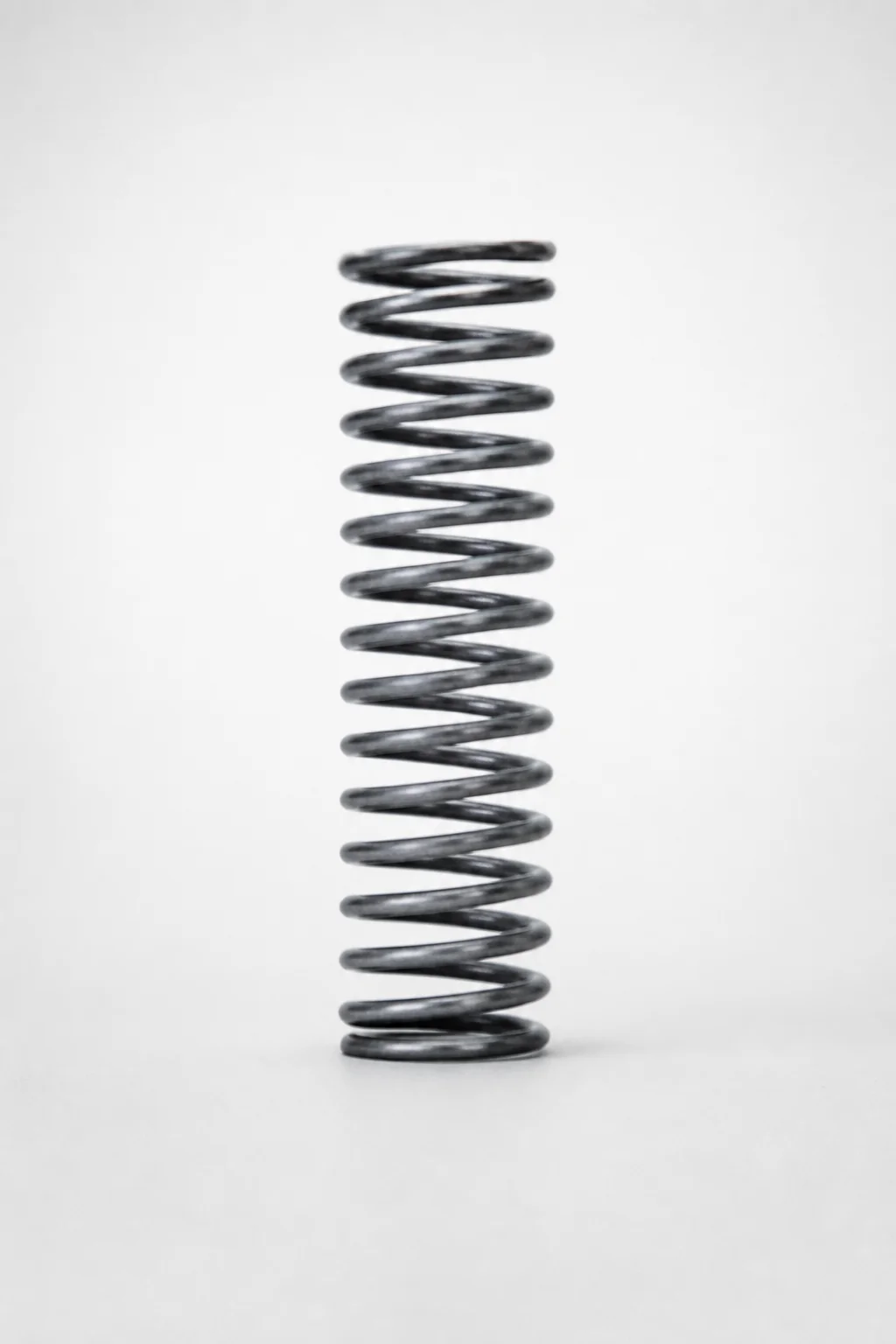
Piano Wire Round Wire Coil Springs - 40% Deflection, WL Series
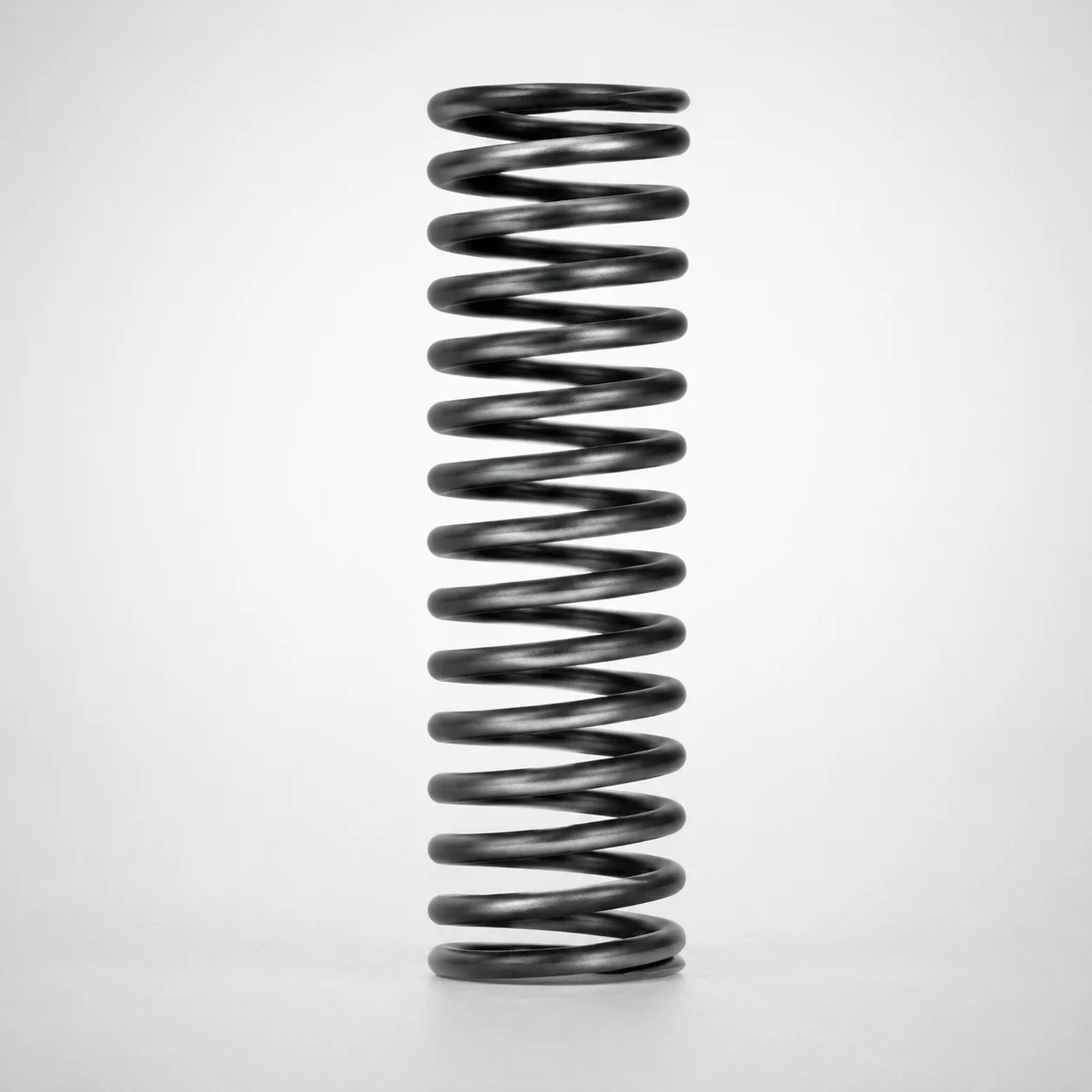
WT Series Round Wire Coil Springs 40% Deflection
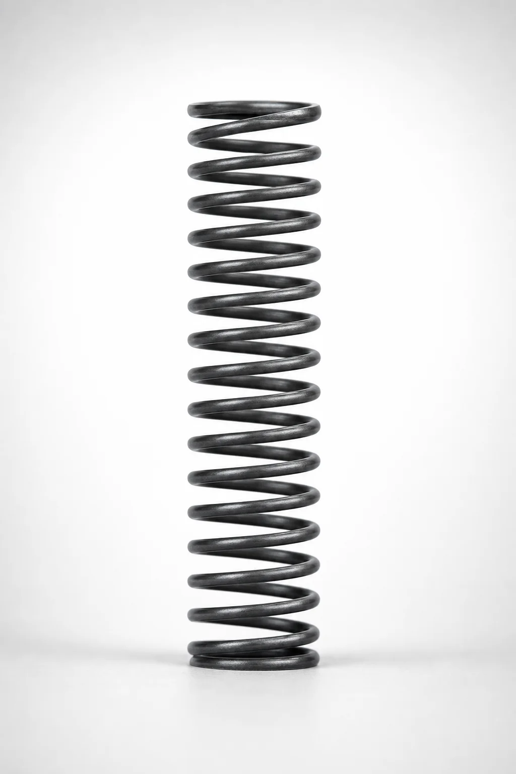
WM Series Round Wire Coil Springs 35% Deflection
Need Custom Specifications?
Our engineering team can help with custom configurations, material selection, and volume pricing.