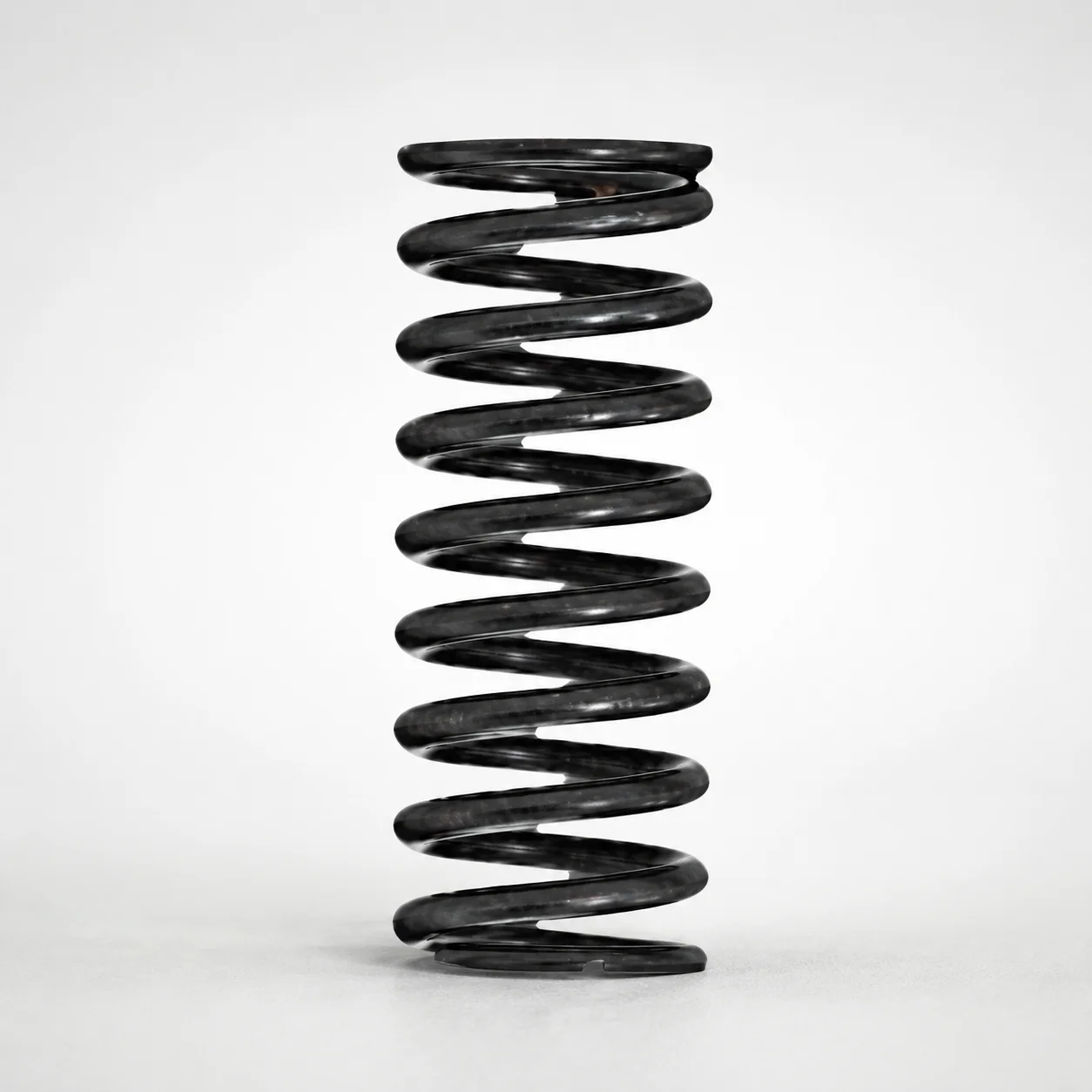
Round Wire Coil Springs - 75% Deflection, WY Series
Round Wire Coil Springs - 75% Deflection, WY Series are designed for predictable load response at higher deflection ratios. The WY type round-wire construction helps maintain consistent performance in mechanical assemblies.
- Built for 75% allowable deflection ratio to match controlled force requirements
- WY type round wire spring geometry supports stable spring characteristics
- Spring constant and maximum load can be selected within the available ranges for fitment
- Common for industrial mechanisms needing compact, repeatable compression spring action
Specifications
83 configurations available
| Spring Constant (N/mm) | Maximum Load (N) | Outer Diameter D (mm) | Length L (mm) | type |
|---|---|---|---|---|
| 0.1 | 0.38 | 3 | 5 | - |
| 0.1 | 0.75 | 3 | 10 | - |
| 0.1 | 1.12 | 3 | 15 | - |
| 0.1 | 1.5 | 3 | 20 | - |
| 0.1 | 1.87 | 3 | 25 | - |
| 0.1 | 2.25 | 3 | 30 | - |
| 0.1 | 0.38 | 4 | 5 | - |
| 0.1 | 0.7 | 4 | 10 | - |
| 0.1 | 1.1 | 4 | 15 | - |
| 0.1 | 1.5 | 4 | 20 | - |
| 0.1 | 1.8 | 4 | 25 | - |
| 0.1 | 2.2 | 4 | 30 | - |
| 0.1 | 2.6 | 4 | 35 | - |
| 0.1 | 2.9 | 4 | 40 | - |
| 0.1 | 0.7 | 5 | 10 | - |
| 0.1 | 1.1 | 5 | 15 | - |
| 0.1 | 1.5 | 5 | 20 | - |
| 0.1 | 1.8 | 5 | 25 | - |
| 0.1 | 2.2 | 5 | 30 | - |
| 0.1 | 2.6 | 5 | 35 | - |
| 0.1 | 2.9 | 5 | 40 | - |
| 0.1 | 3.3 | 5 | 45 | - |
| 0.1 | 3.7 | 5 | 50 | - |
| 0.1 | 0.75 | 6 | 10 | - |
| 0.1 | 1.1 | 6 | 15 | - |
| 0.1 | 1.5 | 6 | 20 | - |
| 0.1 | 1.8 | 6 | 25 | - |
| 0.1 | 2.2 | 6 | 30 | - |
| 0.1 | 2.6 | 6 | 35 | - |
| 0.1 | 2.9 | 6 | 40 | - |
| 0.1 | 3.3 | 6 | 45 | - |
| 0.1 | 3.7 | 6 | 50 | - |
| 0.1 | 4.0 | 6 | 55 | - |
| 0.1 | 4.4 | 6 | 60 | - |
| 0.1 | 4.8 | 6 | 65 | - |
| 0.1 | 5.1 | 6 | 70 | - |
| 0.1 | 0.75 | 8 | 10 | - |
| 0.1 | 1.1 | 8 | 15 | - |
| 0.1 | 1.5 | 8 | 20 | - |
| 0.1 | 1.8 | 8 | 25 | - |
| 0.1 | 2.2 | 8 | 30 | - |
| 0.1 | 2.6 | 8 | 35 | - |
| 0.1 | 2.9 | 8 | 40 | - |
| 0.1 | 3.3 | 8 | 45 | - |
| 0.1 | 3.7 | 8 | 50 | - |
| 0.1 | 4.0 | 8 | 55 | - |
| 0.1 | 4.4 | 8 | 60 | - |
| 0.1 | 4.8 | 8 | 65 | - |
| 0.1 | 5.1 | 8 | 70 | - |
| 0.2 | 2.26 | 10 | 15 | - |
Product Guide
Application Scenarios+
This round-wire coil spring is used inside injection-molded assemblies where a controlled compression force is required over a defined travel. A typical use case is automotive and industrial connectors, where the spring must maintain predictable load response despite tolerance stack-up during engagement and latching.
Another common application is medical and lab device mechanisms (e.g., cartridge retention, hinged closures, or actuator returns). The 75% deflection design supports repeatable force levels at higher deflection ratios, helping reduce variation in feel and actuation performance.
It is also suited for consumer electronics and office equipment snap-fit mechanisms, where compact space is limited. With an outer diameter range of 3–16 mm and length 5–70 mm, engineers can select a matching size to achieve the targeted spring constant and maximum load without redesigning the housing geometry.
- 75% allowable deflection ratio supports controlled spring response at higher travel
- WY geometry helps maintain stable characteristics in dynamic assembly conditions
Material & Process Details+
The provided metadata does not specify the steel grade, heat-treatment condition, or hardness (HRC) for this WY series spring. Because coil-spring performance (fatigue life, wear resistance, and load stability) is strongly tied to the material grade and tempering process, exact comparisons to steels (e.g., SKH51/AISI M2 or SKD61/H13 equivalents) cannot be confirmed from the supplied information.
For engineering selection, treat the spring as a finished spring product where the manufacturer’s wire material, forming method, and tempering are already optimized to meet the stated spring constant and maximum load ranges. If fatigue life or repeated cycling is a critical requirement, request the material specification and heat-treatment/hardness data to confirm toughness vs. wear/fatigue trade-offs.
- Material grade and heat treatment: not provided in this dataset
- Hardness (HRC): not provided
- Performance alignment: use provided k (0.1, 0.2 N/mm) and max load (0.38–10.3 N) for sizing
Sizing & Selection Guide+
To select the correct spring, start with the required force at the operating travel and confirm it fits within your available envelope. This WY series is specified for an allowable deflection ratio of 75%, meaning you should plan the working deflection so the spring operates within that limit to maintain the intended response.
Next, match the mechanical requirements using the available spring constant and loading capability. Choose between spring constant k = 0.1 or 0.2 N/mm and verify the expected load level falls within the provided maximum load of 0.38–10.3 N.
- Outer diameter D: select within 3–16 mm to clear the guide and housing walls
- Free length L: select within 5–70 mm based on the available stack height in the mold tool/assembly
Finally, account for fitment and tolerance stack-up: the D dimension should consider clearance to avoid binding, while L must accommodate installed length after compression. If you are close to bounds, select the next compatible size and re-check force vs. travel to keep operation under the 75% deflection limit.
Frequently Asked Questions
How do I apply the 75% deflection ratio to choose the working travel for a WY series coil spring?+
The dataset specifies an allowable deflection ratio of 75%. For design, keep the spring’s operating compression within that ratio of its allowable/selected deflection so the force response remains predictable for your assembly.
Because only spring constant (0.1 or 0.2 N/mm) and max load (0.38–10.3 N) are provided, calculate the expected load from the required deflection and confirm it does not exceed the selected maximum load.
What spring constant options are available, and how should I select between 0.1 and 0.2 N/mm?+
For this WY series, the available spring constant (N/mm) is 0.1 or 0.2.
Select 0.1 N/mm when you need lower force per unit travel, and 0.2 N/mm when you need a stiffer response. After choosing k, verify the resulting force at your planned deflection remains within the provided maximum load range (0.38–10.3 N).
How do outer diameter (D) and length (L) constraints affect spring fit in an injection-molded housing?+
The spring’s outer diameter D is available from 3–16 mm, and the length L is available from 5–70 mm.
Ensure D provides clearance against guide features to prevent binding, and ensure L allows the required installed/stack height without exceeding the allowable deflection ratio. If your design is near the limits, choose a size with margin and re-check load vs. travel using the selected spring constant.
Can I confirm the steel grade, heat treatment, or hardness for this WY round-wire coil spring from the provided specs?+
The supplied data does not list the steel grade, heat-treatment condition, or hardness (HRC).
Therefore, you cannot reliably match it to specific tool steels (e.g., SKH51/AISI M2 or SKD61/H13 equivalents) based on this dataset alone. For fatigue-life-critical designs, request the material and tempering information from the supplier.
What is the relationship between maximum load and the selected spring constant and deflection during assembly?+
The dataset provides maximum load values in the range 0.38–10.3 N and spring constants of 0.1 or 0.2 N/mm.
Use the selected spring constant to estimate force at the planned working deflection, then confirm the calculated force stays below the chosen product’s maximum load. Also ensure the compression stays within the 75% allowable deflection ratio for stable response.
Related Products
WR Series Round Wire Coil Springs 60% Deflection
Round Wire Coil Springs - 45% Deflection WF Series
Piano Wire Round Wire Coil Springs - 40% Deflection, WL Series
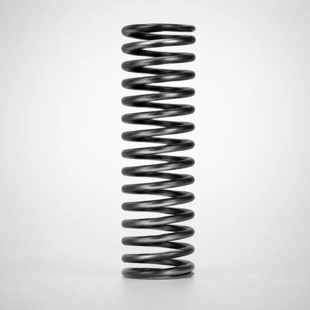
WT Series Round Wire Coil Springs 40% Deflection
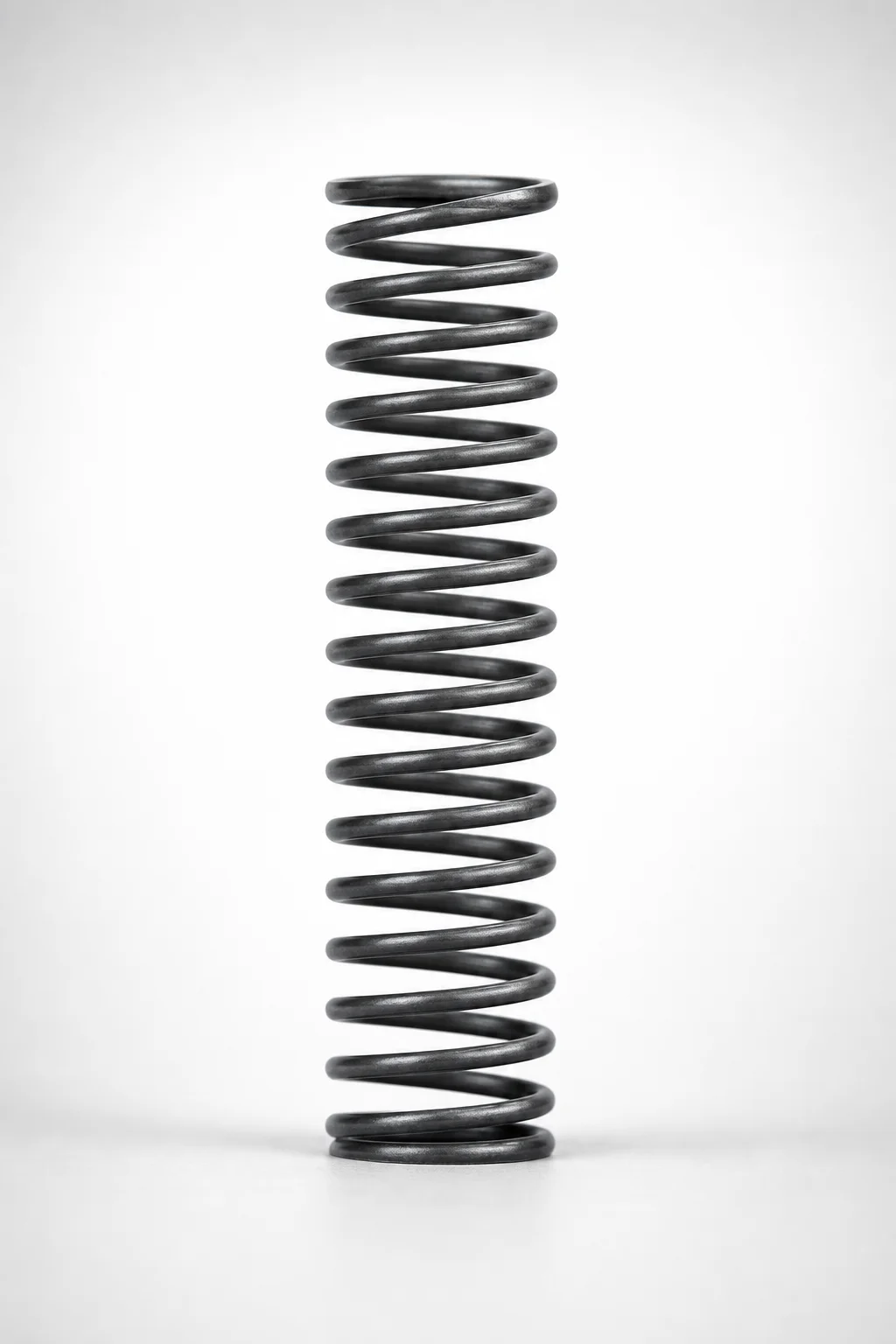
WM Series Round Wire Coil Springs 35% Deflection
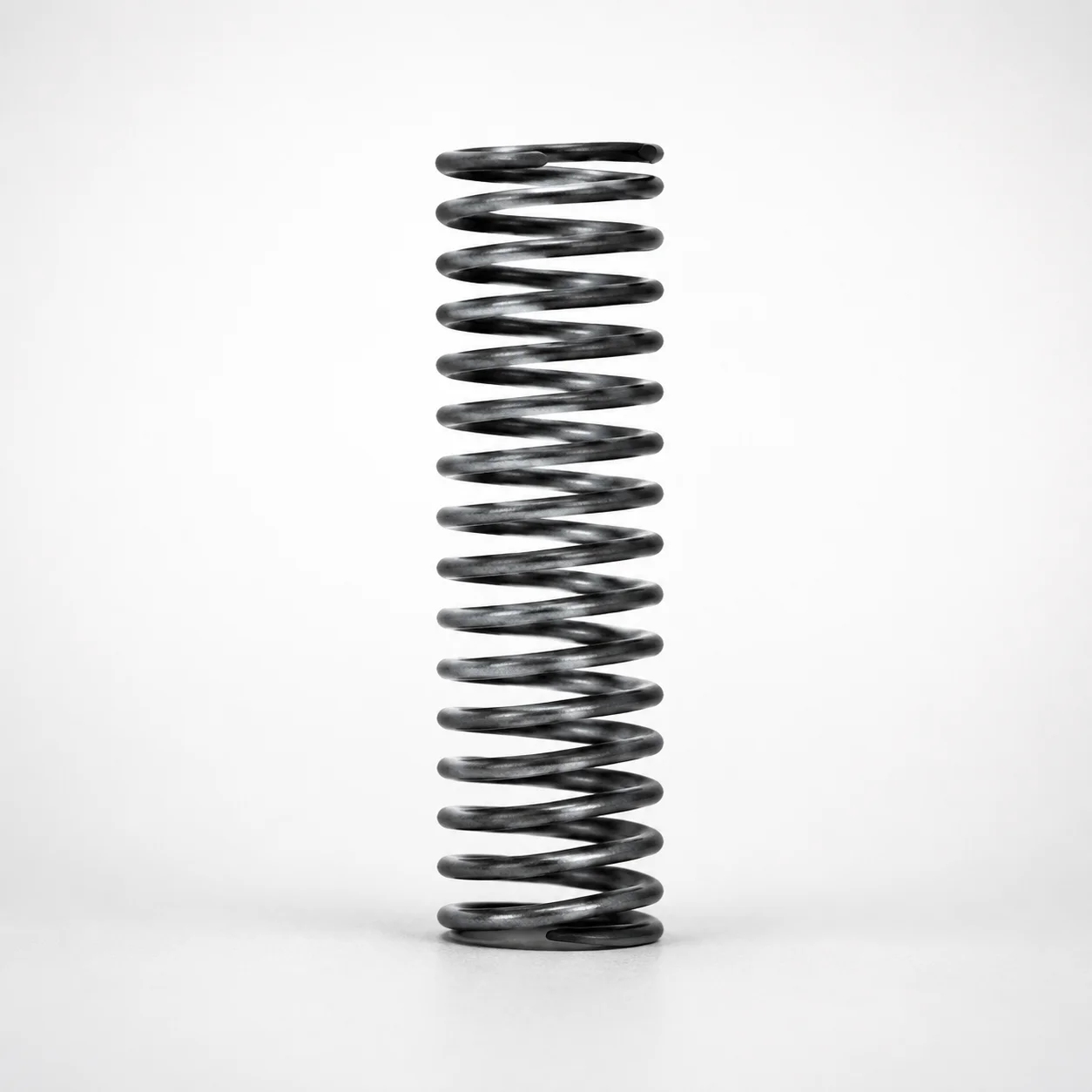
WH Series Round Wire Coil Springs - 30% Deflection
Need Custom Specifications?
Our engineering team can help with custom configurations, material selection, and volume pricing.