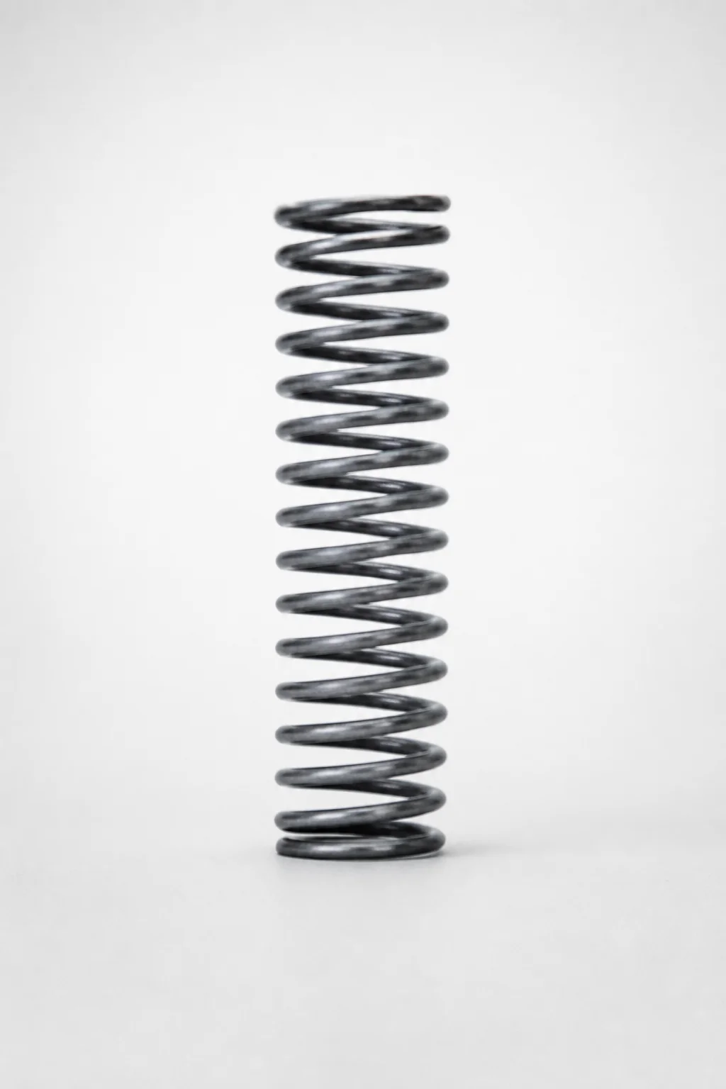
Piano Wire Round Wire Coil Springs - 40% Deflection, WL Series
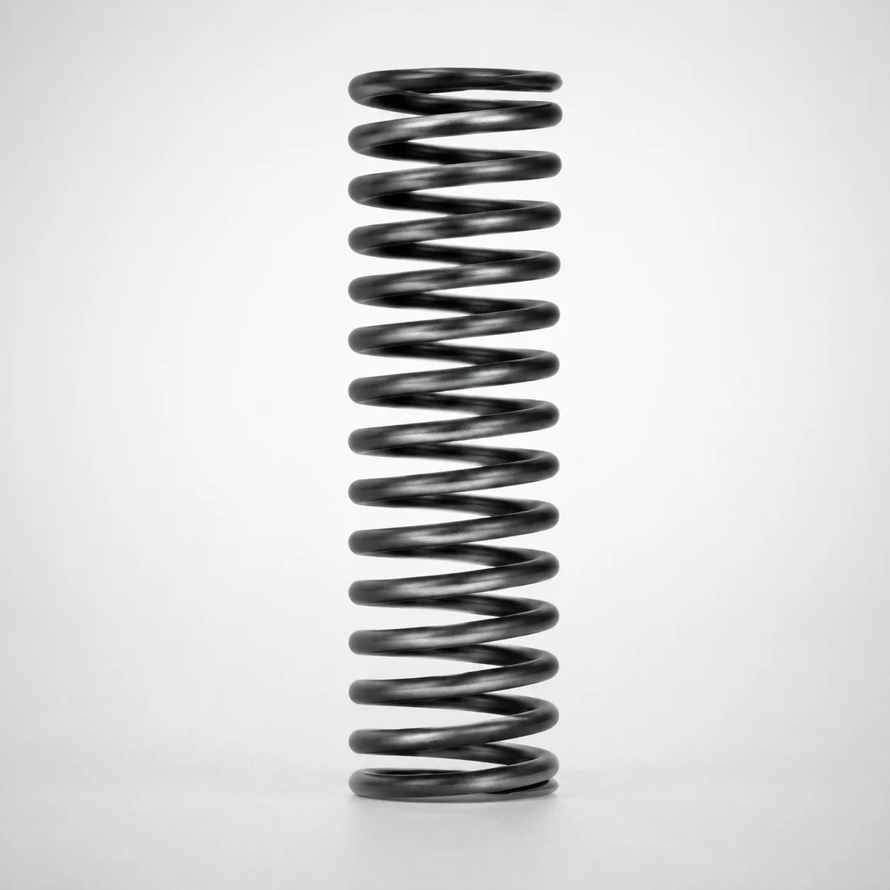
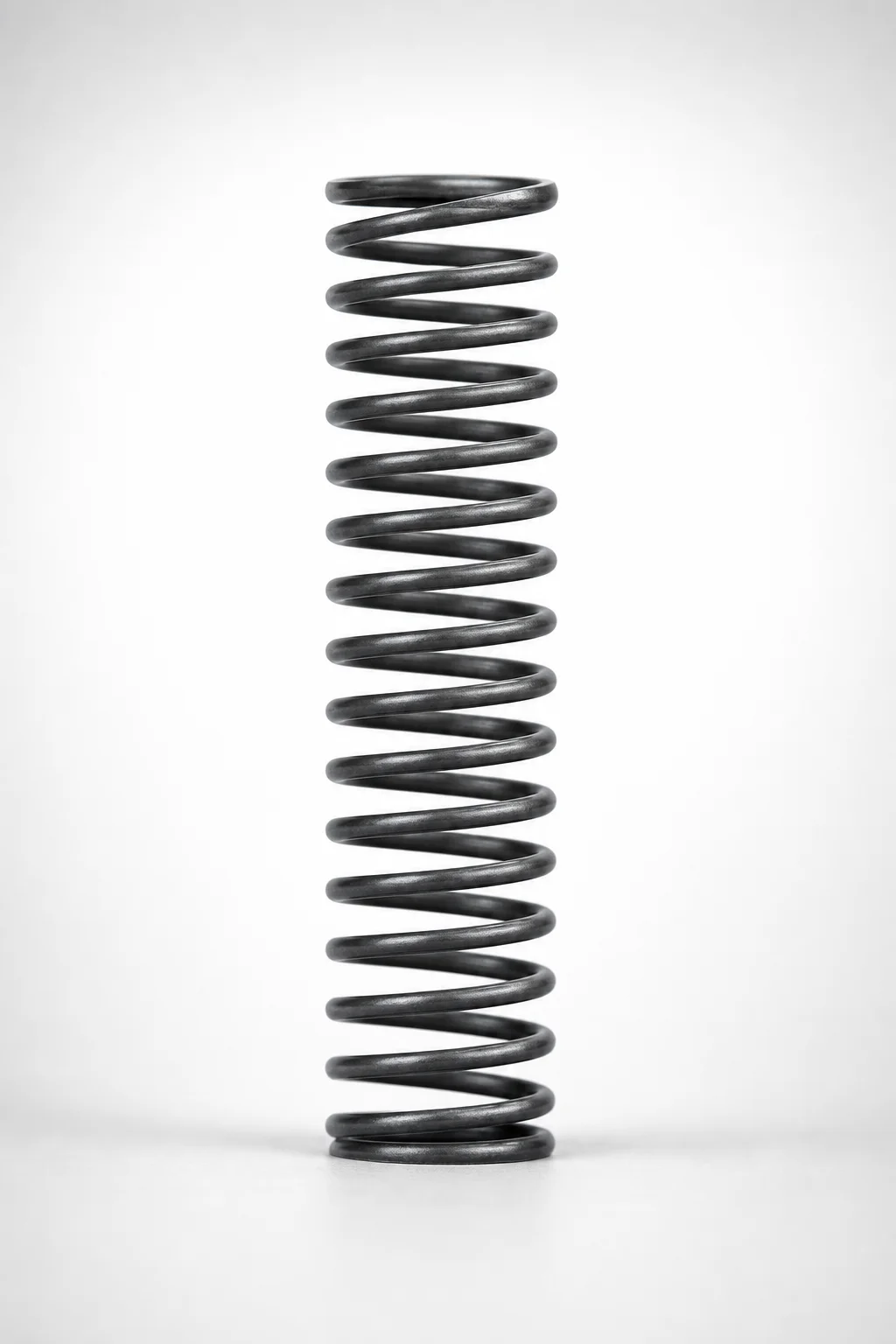
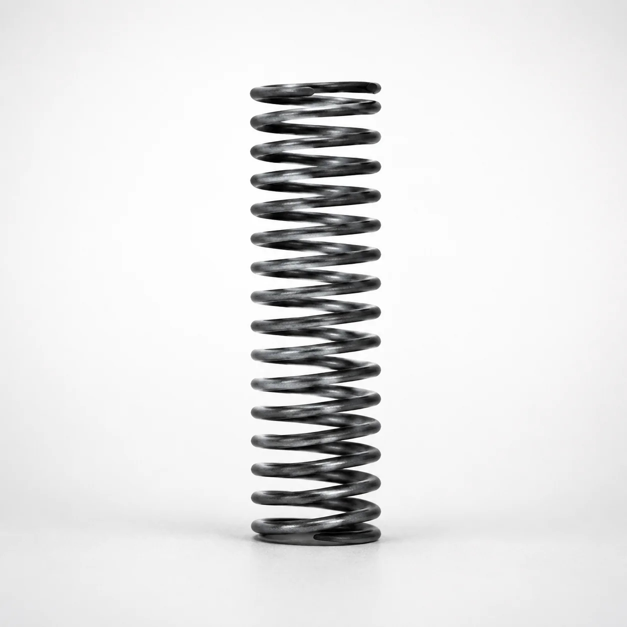
Round wire coil springs - 40% deflection, WL series are precision-formed from piano wire to provide a controlled spring response and reliable force under specified deflection. This design supports consistent performance in motion, clamping, and load-holding mechanisms.
- Built for 40% allowable deflection to maintain stable force characteristics
- Made from piano wire for uniform elasticity and predictable spring behavior
- Configurable spring constant and maximum load options for matching your required duty
- WL series round-wire geometry with type WL for dependable repeatability in assemblies
Specifications
194 configurations available
| Spring Constant (N/mm) | Maximum Load (N) | Outer Diameter D (mm) | Length L (mm) | type |
|---|---|---|---|---|
| 0.5 | 0.98 | 2 | 5 | - |
| 0.5 | 2.0 | 2 | 10 | - |
| 0.5 | 2.9 | 2 | 15 | - |
| 0.5 | 3.9 | 2 | 20 | - |
| 0.5 | 4.9 | 2 | 25 | - |
| 0.5 | 5.9 | 2 | 30 | - |
| 1.0 | 2.0 | 3 | 5 | - |
| 1.0 | 3.9 | 3 | 10 | - |
| 1.0 | 5.9 | 3 | 15 | - |
| 1.0 | 7.8 | 3 | 20 | - |
| 1.0 | 9.8 | 3 | 25 | - |
| 1.0 | 11.8 | 3 | 30 | - |
| 1.0 | 13.7 | 3 | 35 | - |
| 1.0 | 15.7 | 3 | 40 | - |
| 1.0 | 2.0 | 4 | 5 | - |
| 1.0 | 3.9 | 4 | 10 | - |
| 1.0 | 5.9 | 4 | 15 | - |
| 1.0 | 7.8 | 4 | 20 | - |
| 1.0 | 9.8 | 4 | 25 | - |
| 1.0 | 11.8 | 4 | 30 | - |
| 1.0 | 13.7 | 4 | 35 | - |
| 1.0 | 15.7 | 4 | 40 | - |
| 1.0 | 17.7 | 4 | 45 | - |
| 1.0 | 19.6 | 4 | 50 | - |
| 1.0 | 21.6 | 4 | 55 | - |
| 1.0 | 23.5 | 4 | 60 | - |
| 1.0 | 2.0 | 5 | 5 | - |
| 1.0 | 3.9 | 5 | 10 | - |
| 1.0 | 5.9 | 5 | 15 | - |
| 1.0 | 7.8 | 5 | 20 | - |
| 1.0 | 9.8 | 5 | 25 | - |
| 1.0 | 11.8 | 5 | 30 | - |
| 1.0 | 13.7 | 5 | 35 | - |
| 1.0 | 15.7 | 5 | 40 | - |
| 1.0 | 17.7 | 5 | 45 | - |
| 1.0 | 19.6 | 5 | 50 | - |
| 1.0 | 21.6 | 5 | 55 | - |
| 1.0 | 23.5 | 5 | 60 | - |
| 1.0 | 25.5 | 5 | 65 | - |
| 1.0 | 27.5 | 5 | 70 | - |
| 1.0 | 2.0 | 6 | 5 | - |
| 1.0 | 3.9 | 6 | 10 | - |
| 1.0 | 5.9 | 6 | 15 | - |
| 1.0 | 7.8 | 6 | 20 | - |
| 1.0 | 9.8 | 6 | 25 | - |
| 1.0 | 11.8 | 6 | 30 | - |
| 1.0 | 13.7 | 6 | 35 | - |
| 1.0 | 15.7 | 6 | 40 | - |
| 1.0 | 17.7 | 6 | 45 | - |
| 1.0 | 19.6 | 6 | 50 | - |
Product Guide
Application Scenarios+
This round-wire coil spring variant is used inside precision injection mold tooling where a consistent force over stroke is required—especially in mechanisms that must maintain repeatability across cycles.
- Automotive connector and terminal molds: suited for ejector or slide return support, where maintaining a stable force curve through 40% allowable deflection helps prevent sticking and improves cycle-to-cycle uniformity.
- Medical device housing molds: used in load-holding or micro-actuation features that require predictable spring response to keep components clamped during post-mold handling.
- Consumer electronics insert molds: ideal for motion or clamping systems that benefit from piano-wire elasticity and controllable spring constant selection for your required opening/closing timing.
The WL-series geometry and piano-wire construction support uniform elastic behavior, enabling engineers to tune spring rate via the available spring constant (0.5, 1.0, 2.9 N/mm) and match maximum load needs.
Material & Process Details+
This product is specified as piano wire (music-wire style), selected for its high elastic uniformity and predictable spring-back in compression or extension strokes.
- Material behavior: piano wire typically provides high wear resistance at the spring surface and excellent fatigue performance when deflection stays within the designed allowable range (here, 40% deflection).
- Heat treatment (typical for piano wire): wire is commonly supplied in a hardened condition and finished for spring use; for maximum life, it is expected to be manufactured to spring-grade mechanical properties rather than annealed steel.
- Trade-offs: higher hardness improves fatigue strength and wear resistance, but can reduce toughness margin—reinforcing the importance of selecting the correct length and working load.
If you compare alternatives, pre-hardened spring steels may be easier to form but often require more careful rate validation; the piano-wire approach emphasizes stable elasticity for controlled force curves.
Sizing & Selection Guide+
Select spring dimensions first, then confirm the force/load envelope for your mechanism so operation stays within the designed allowable deflection.
- Outer diameter (OD), D: choose from 2–27 mm to match surrounding guide clearances in your mold cavity/core layout and to avoid interference with neighboring components.
- Free length, L: use the available 5–100 mm range, then calculate your expected compression/extension stroke so the working deflection does not exceed the 40% allowable deflection requirement.
- Spring constant (k): pick 0.5, 1.0, or 2.9 N/mm to achieve the required force response over your stroke.
- Maximum load: verify the spring’s specified 0.98–117.7 N maximum load covers your highest expected operating load with a safety margin.
Tolerances are not provided in the supplied data; therefore, validate fit by checking your assembly clearance and allowing for normal spring manufacturing variations.
Frequently Asked Questions
How do I choose between the available spring constants (0.5, 1.0, 2.9 N/mm) for an injection mold return mechanism?+
What OD (D) and length (L) ranges should I design around for compatibility with mold guides and clearances?+
How do I verify the working load so the spring does not exceed the specified maximum load?+
Does the WL series provide a stable force curve, and how does the 40% deflection limit affect design?+
Is this spring suitable for load-holding/clamping in precision mold inserts where repeatability is critical?+
Related Products
Need Custom Specifications?
Our engineering team can help with custom configurations, material selection, and volume pricing.