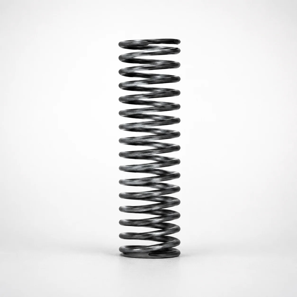
WH Series Round Wire Coil Springs - 30% Deflection
WH Series round wire coil springs - 30% deflection deliver controlled support for equipment that needs reliable shock absorption and stable performance. Their engineered geometry helps maintain consistent force across demanding mechanical operating cycles.
- Designed for 30% deflection to match application-specific support and damping needs
- Round wire construction supports smooth loading and reliable return under cyclic stress
- Selectable spring constant and maximum load options for tuned performance, from 2.9 to 14.7 N/mm
- Ideal for automotive and industrial machinery where equipment longevity depends on durable spring action
Specifications
163 configurations available
| Spring Constant (N/mm) | Allowable Deflection Ratio (%) | Maximum Load (N) | Outer Diameter D (mm) | Length L (mm) | type |
|---|---|---|---|---|---|
| 2.9 | 30 | 4.9 | 4 | 5 | - |
| 2.9 | 30 | 8.8 | 4 | 10 | - |
| 2.9 | 30 | 13.7 | 4 | 15 | - |
| 2.9 | 30 | 17.7 | 4 | 20 | - |
| 2.9 | 30 | 22.6 | 4 | 25 | - |
| 2.9 | 30 | 26.5 | 4 | 30 | - |
| 5.9 | 30 | 8.8 | 5 | 5 | - |
| 5.9 | 30 | 17.7 | 5 | 10 | - |
| 5.9 | 30 | 26.5 | 5 | 15 | - |
| 5.9 | 30 | 35.3 | 5 | 20 | - |
| 5.9 | 30 | 44.1 | 5 | 25 | - |
| 5.9 | 25 | 44.3 | 5 | 30 | - |
| 5.9 | 25 | 51.6 | 5 | 35 | - |
| 5.9 | 22 | 51.9 | 5 | 40 | - |
| 5.9 | 30 | 8.8 | 6 | 5 | - |
| 5.9 | 30 | 17.7 | 6 | 10 | - |
| 5.9 | 30 | 26.5 | 6 | 15 | - |
| 5.9 | 30 | 35.3 | 6 | 20 | - |
| 5.9 | 30 | 44.1 | 6 | 25 | - |
| 5.9 | 30 | 53.0 | 6 | 30 | - |
| 5.9 | 30 | 61.8 | 6 | 35 | - |
| 5.9 | 30 | 70.6 | 6 | 40 | - |
| 5.9 | 25 | 66.7 | 6 | 45 | - |
| 5.9 | 20 | 58.8 | 6 | 50 | - |
| 5.9 | 26 | 85.3 | 6 | 55 | - |
| 5.9 | 23 | 82.4 | 6 | 60 | - |
| 5.9 | 21 | 82.4 | 6 | 65 | - |
| 5.9 | 21 | 88.3 | 6 | 70 | - |
| 5.9 | 30 | 17.7 | 8 | 10 | - |
| 5.9 | 30 | 26.5 | 8 | 15 | - |
| 5.9 | 30 | 35.3 | 8 | 20 | - |
| 5.9 | 30 | 44.1 | 8 | 25 | - |
| 5.9 | 30 | 53.0 | 8 | 30 | - |
| 5.9 | 30 | 61.8 | 8 | 35 | - |
| 5.9 | 30 | 70.6 | 8 | 40 | - |
| 5.9 | 30 | 79.4 | 8 | 45 | - |
| 5.9 | 30 | 88.3 | 8 | 50 | - |
| 5.9 | 30 | 97.1 | 8 | 55 | - |
| 5.9 | 30 | 105.9 | 8 | 60 | - |
| 5.9 | 26 | 100.0 | 8 | 65 | - |
| 5.9 | 27 | 111.8 | 8 | 70 | - |
| 5.9 | 30 | 17.7 | 10 | 10 | - |
| 5.9 | 30 | 26.5 | 10 | 15 | - |
| 5.9 | 30 | 35.3 | 10 | 20 | - |
| 5.9 | 30 | 44.1 | 10 | 25 | - |
| 5.9 | 30 | 53.0 | 10 | 30 | - |
| 5.9 | 30 | 61.8 | 10 | 35 | - |
| 5.9 | 30 | 70.6 | 10 | 40 | - |
| 5.9 | 30 | 79.4 | 10 | 45 | - |
| 5.9 | 30 | 88.3 | 10 | 50 | - |
Product Guide
Application Scenarios+
WH-series round-wire coil springs with 30% deflection are used in injection mold tooling where controlled force and repeatable shock absorption protect precision components during cycling. In automotive connector and housing molds, they help maintain stable return action for small ejecting or actuated mechanisms, reducing load variation that can affect part dimensional stability.
They are also well-suited for industrial machinery mold assemblies that experience vibration and frequent open/close cycles. The round-wire form supports smoother loading and reliable reset under cyclic stress, which supports consistent damping and reduces the risk of chatter or uneven actuation.
For test fixtures and modular tooling, the selectable spring constant (2.9 to 14.7 N/mm) and maximum load range (4.9 to 441.3 N) allow engineers to tune the force to the mechanism’s allowable deflection window (20–30%). This variant’s designed deflection ratio alignment improves force predictability at the target travel.
Material & Process Details+
The provided metadata does not specify the steel grade or any heat-treatment state (e.g., quench & temper, nitriding). For accurate material selection in high-cycle mold environments, confirm the spring material specification from the supplier documentation tied to the selected spring constant (2.9, 5.9, 9.8, or 14.7 N/mm) and size (D 4–27 mm; L 5–100 mm).
In general spring steel selection trades off hardness and wear resistance against toughness to manage fatigue life. Higher hardness can improve resistance to set and surface wear, while reduced toughness may increase sensitivity to shock loading and stress concentration.
- Verify target hardness (HRC) and fatigue design basis for cyclic tooling use.
- Confirm heat treatment (pre-hardened vs. quenched & tempered) to ensure dimensional stability at operating temperatures.
- If multiple materials are offered, compare fatigue strength and expected relaxation rate under your deflection ratio (20–30%).
Sizing & Selection Guide+
Selection is driven by the required stiffness and allowable travel. Start by matching your mechanism’s intended travel to the specified allowable deflection ratio of 20–30%. For this product variant, the design target is 30% deflection, so choose the operating point close to this value to maintain predictable force.
Next, match the load requirement using the spring constant: choose from 2.9, 5.9, 9.8, or 14.7 N/mm. Then verify the corresponding maximum load needs fall within 4.9 to 441.3 N to avoid under-design (insufficient force) or overloading (premature fatigue/setting).
- Check geometry: outer diameter D = 4–27 mm and free length L = 5–100 mm.
- Ensure installed length leaves adequate stroke margin for your compression at 30% deflection.
- Where space is constrained, prioritize D first (spring clearance) and then L (available travel), while accounting for any assembly tolerances in seat alignment.
Frequently Asked Questions
How do I select the correct spring constant for a tooling mechanism targeting 30% deflection?+
What deflection ratio should I use in my force calculation—20–30% or exactly 30%?+
How do D (outer diameter) and L (length) ranges affect compatibility with an ejector or actuating system?+
How can I ensure the selected spring won’t exceed maximum load in repetitive mold cycling?+
Is there any material or hardness data available to verify fatigue life for mold tooling?+
Related Products
Round Wire Coil Springs - 75% Deflection, WY Series
WR Series Round Wire Coil Springs 60% Deflection
Round Wire Coil Springs - 45% Deflection WF Series
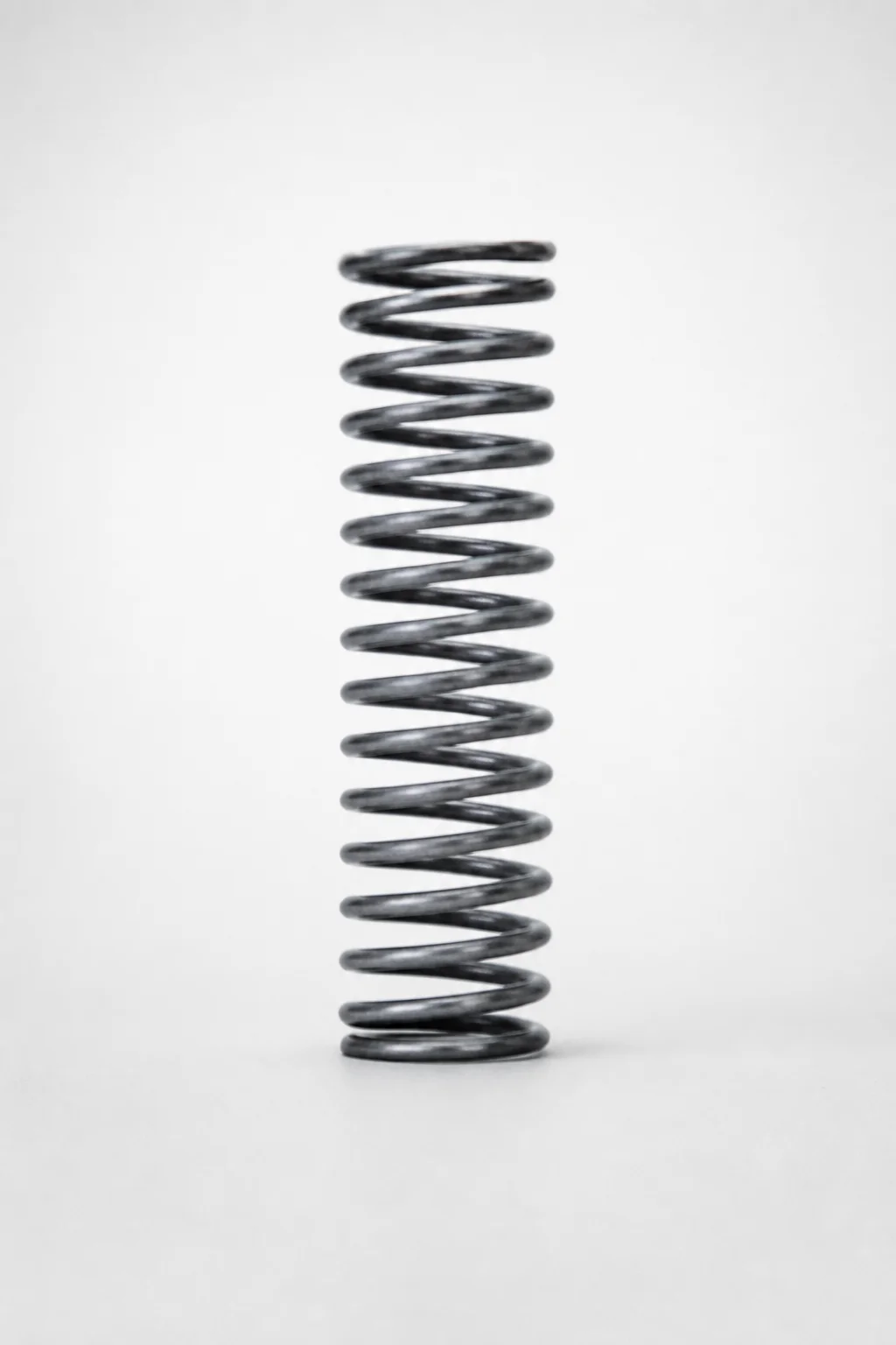
Piano Wire Round Wire Coil Springs - 40% Deflection, WL Series
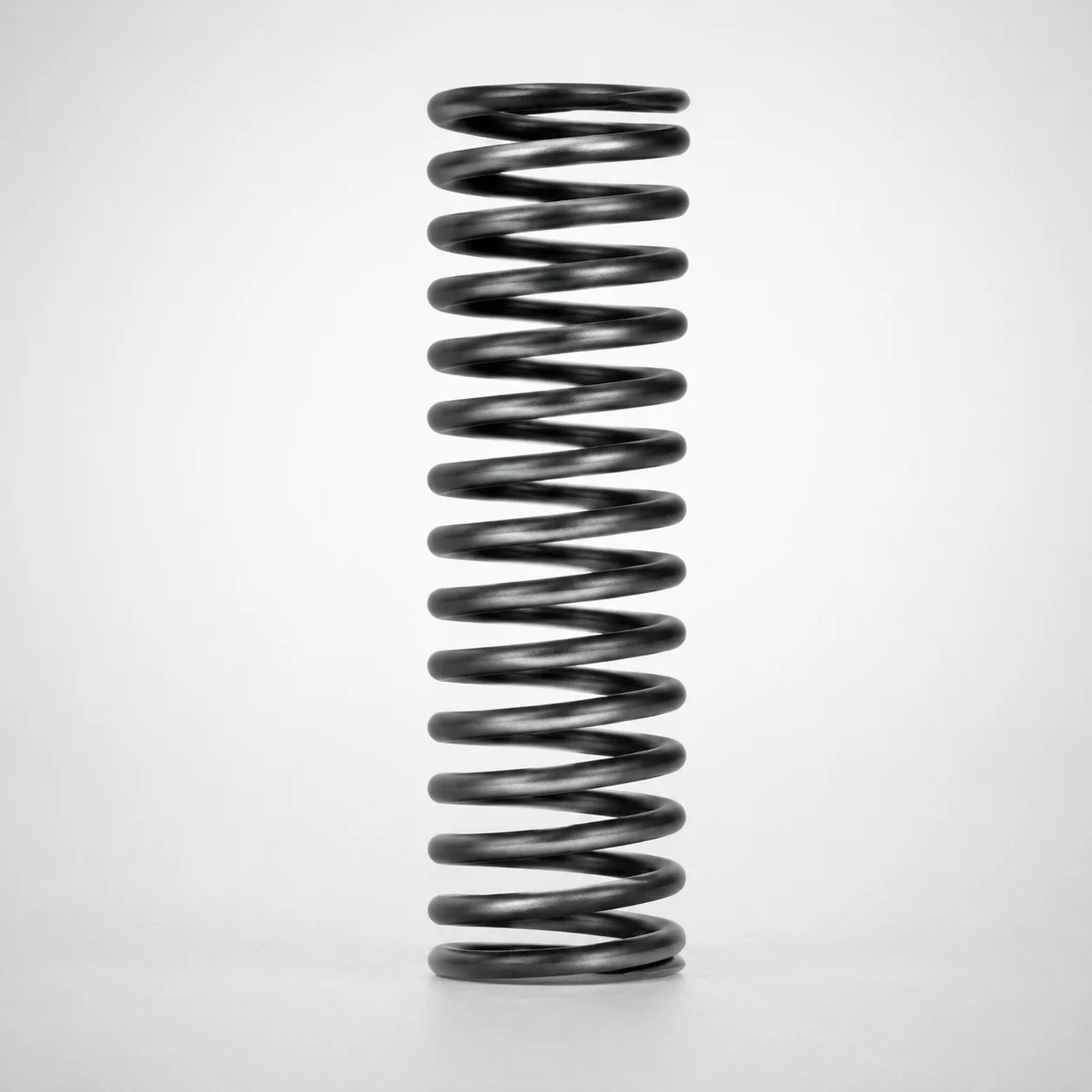
WT Series Round Wire Coil Springs 40% Deflection
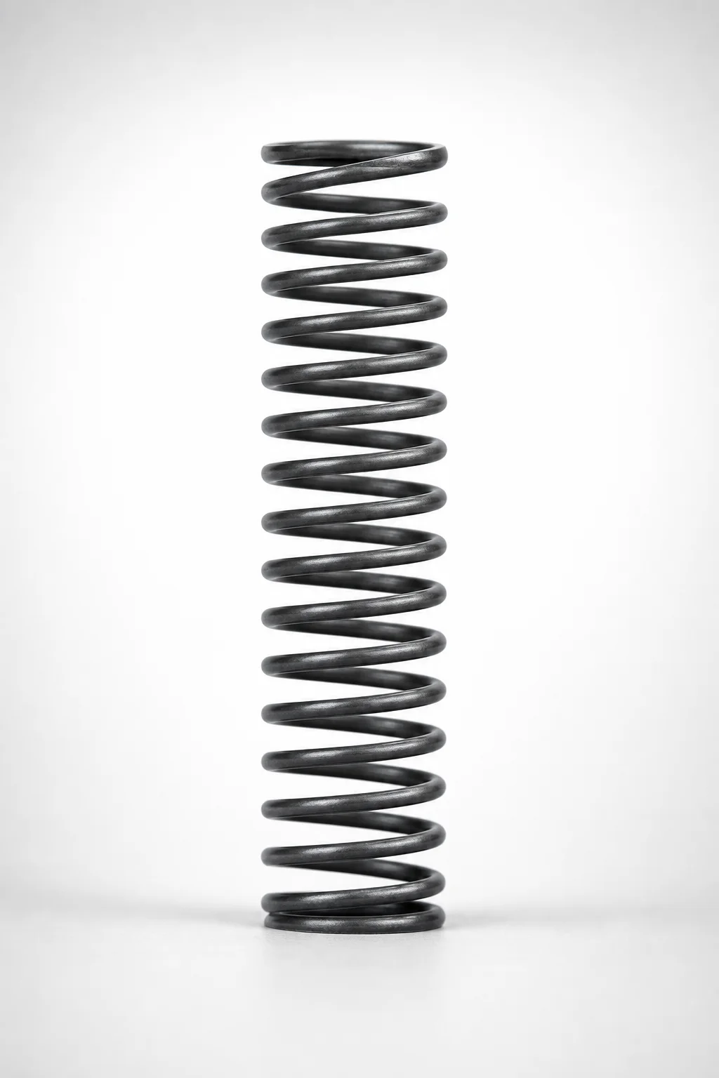
WM Series Round Wire Coil Springs 35% Deflection
Need Custom Specifications?
Our engineering team can help with custom configurations, material selection, and volume pricing.