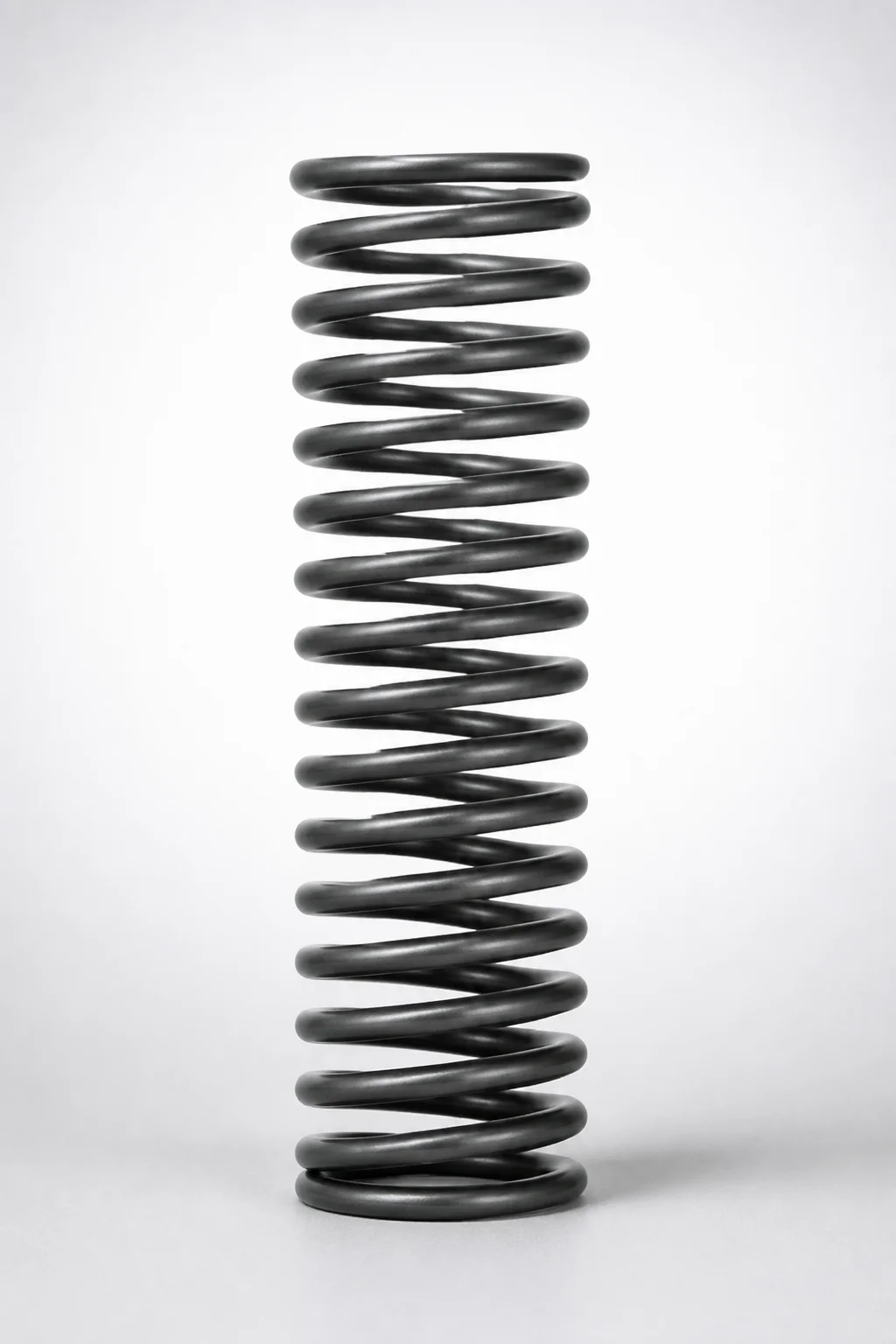
WR Series Round Wire Coil Springs 60% Deflection
WR Series round wire coil springs 60% deflection deliver predictable load response for compression and spring return applications. The 60% deflection rating helps engineers size force requirements with consistent performance.
- 60% deflection design supports controlled force under working stroke
- Type WR round-wire construction for smooth, stable spring action
- Options for spring constant (N/mm) 0.3 or 0.5 to match target loads
- Selectable outer diameter 3–27 mm for fit across mechanisms
Specifications
182 configurations available
| Spring Constant (N/mm) | Maximum Load (N) | Outer Diameter D (mm) | Length L (mm) | type |
|---|---|---|---|---|
| 0.3 | 0.9 | 3 | 5 | - |
| 0.3 | 1.8 | 3 | 10 | - |
| 0.3 | 2.6 | 3 | 15 | - |
| 0.3 | 3.5 | 3 | 20 | - |
| 0.3 | 4.4 | 3 | 25 | - |
| 0.3 | 5.3 | 3 | 30 | - |
| 0.3 | 6.2 | 3 | 35 | - |
| 0.3 | 7.1 | 3 | 40 | - |
| 0.3 | 0.9 | 4 | 5 | - |
| 0.3 | 1.8 | 4 | 10 | - |
| 0.3 | 2.6 | 4 | 15 | - |
| 0.3 | 3.5 | 4 | 20 | - |
| 0.3 | 4.4 | 4 | 25 | - |
| 0.3 | 5.3 | 4 | 30 | - |
| 0.3 | 6.2 | 4 | 35 | - |
| 0.3 | 7.1 | 4 | 40 | - |
| 0.3 | 7.9 | 4 | 45 | - |
| 0.3 | 8.8 | 4 | 50 | - |
| 0.3 | 9.7 | 4 | 55 | - |
| 0.3 | 10.6 | 4 | 60 | - |
| 0.3 | 11.5 | 4 | 65 | - |
| 0.3 | 12.4 | 4 | 70 | - |
| 0.3 | 0.9 | 5 | 5 | - |
| 0.3 | 1.8 | 5 | 10 | - |
| 0.3 | 2.6 | 5 | 15 | - |
| 0.3 | 3.5 | 5 | 20 | - |
| 0.3 | 4.4 | 5 | 25 | - |
| 0.3 | 5.3 | 5 | 30 | - |
| 0.3 | 6.2 | 5 | 35 | - |
| 0.3 | 7.1 | 5 | 40 | - |
| 0.3 | 7.9 | 5 | 45 | - |
| 0.3 | 8.8 | 5 | 50 | - |
| 0.3 | 9.7 | 5 | 55 | - |
| 0.3 | 10.6 | 5 | 60 | - |
| 0.3 | 11.5 | 5 | 65 | - |
| 0.3 | 12.4 | 5 | 70 | - |
| 0.3 | 0.9 | 6 | 5 | - |
| 0.3 | 1.8 | 6 | 10 | - |
| 0.3 | 2.6 | 6 | 15 | - |
| 0.3 | 3.5 | 6 | 20 | - |
| 0.3 | 4.4 | 6 | 25 | - |
| 0.3 | 5.3 | 6 | 30 | - |
| 0.3 | 6.2 | 6 | 35 | - |
| 0.3 | 7.1 | 6 | 40 | - |
| 0.3 | 7.9 | 6 | 45 | - |
| 0.3 | 8.8 | 6 | 50 | - |
| 0.3 | 9.7 | 6 | 55 | - |
| 0.3 | 10.6 | 6 | 60 | - |
| 0.3 | 11.5 | 6 | 65 | - |
| 0.3 | 12.4 | 6 | 70 | - |
Product Guide
Application Scenarios+
These round wire coil springs are designed for injection mold tooling where compact, repeatable force is needed during compression and release cycles. The 60% deflection rating provides a controlled load characteristic at a defined working stroke, helping engineers predict actuator behavior and maintain consistent ejection or return force.
- Automotive connector and relay housings: Use in mold mechanisms that require stable spring return after slide or lifter movement; the WR round-wire geometry supports smooth, predictable motion under cyclic loading.
- Medical device component molds: Suitable for precision shutoff or small-force compensation features where consistent force versus stroke reduces variability in part positioning.
- General industrial insert or stripper systems: Select the appropriate spring constant (0.3 or 0.5 N/mm) to match the required force range, while choosing an outer diameter (3–27 mm) that fits the available space.
Pick the variant whose spring constant and dimensions match your cavity/core linkage travel so the spring reaches its target deflection without overloading.
Material & Process Details+
The provided WR Series product data specifies the spring’s performance parameters (spring constant, load, and dimensions) but does not include a steel grade, heat treatment state, or hardness value. As a result, the steel equivalency (e.g., SKD61/H13), HRC hardness, nitriding/carburizing, and specific tempering/quenched condition cannot be stated from the supplied information.
For procurement and design verification, confirm the spring’s material grade and heat treatment with the supplier’s technical sheet for accurate predictions of wear resistance vs. toughness. If multiple material options are offered, engineers typically compare higher-strength grades for improved fatigue life against slightly reduced toughness, depending on cyclic load severity and environment.
- Key missing attributes to request: steel grade, surface treatment (if any), heat treatment condition, and target hardness (HRC).
- Design relevance: these determine fatigue durability under repeated deflection and resistance to relaxation during molding thermal cycles.
Sizing & Selection Guide+
To select the correct WR Series spring, start from your required force at the working stroke and match the 60% deflection design point to your mechanism travel. The spring constant options are 0.3 or 0.5 N/mm; using the chosen constant helps you estimate load versus deflection for the spring return/compression function.
- Outer diameter D (mm): select within 3–27 mm to fit the guide, pocket, or housing space around the spring.
- Length L (mm): choose from 5–90 mm to ensure the spring seats properly in the mold and provides clearance at full compression.
- Maximum load (N): verify the selected size aligns with the stated range of 0.9–23.5 N so the mechanism does not exceed the intended load at the target stroke.
Check tolerance and fit indirectly by confirming the spring’s available outer diameter and length tolerances from the datasheet; if your design uses close clearances, keep accommodation for assembly variation so the spring remains centered and does not bind during cycling.
Frequently Asked Questions
How should I choose between the WR Series spring constants (0.3 vs 0.5 N/mm) for mold return force?+
What dimensions are available for the WR Series round wire coil springs, and which one affects clearance most?+
How do I verify that a selected spring size will not overload the mechanism in compression?+
Do I need to worry about material hardness or heat treatment when selecting the WR Series spring for mold cycles?+
What is the practical way to map cavity/core movement to the spring’s 60% deflection design point?+
Related Products
Round Wire Coil Springs - 75% Deflection, WY Series
Round Wire Coil Springs - 45% Deflection WF Series
Piano Wire Round Wire Coil Springs - 40% Deflection, WL Series
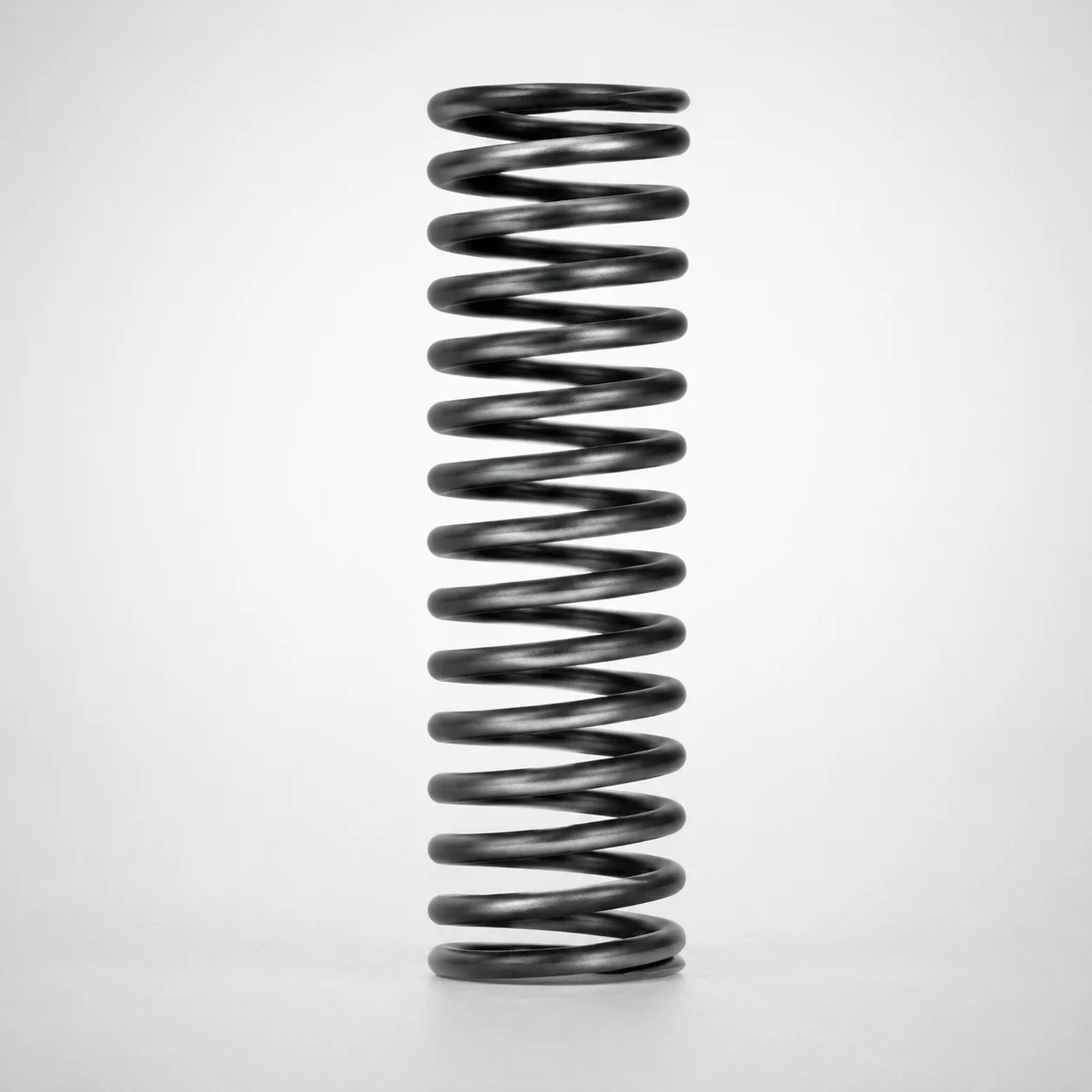
WT Series Round Wire Coil Springs 40% Deflection
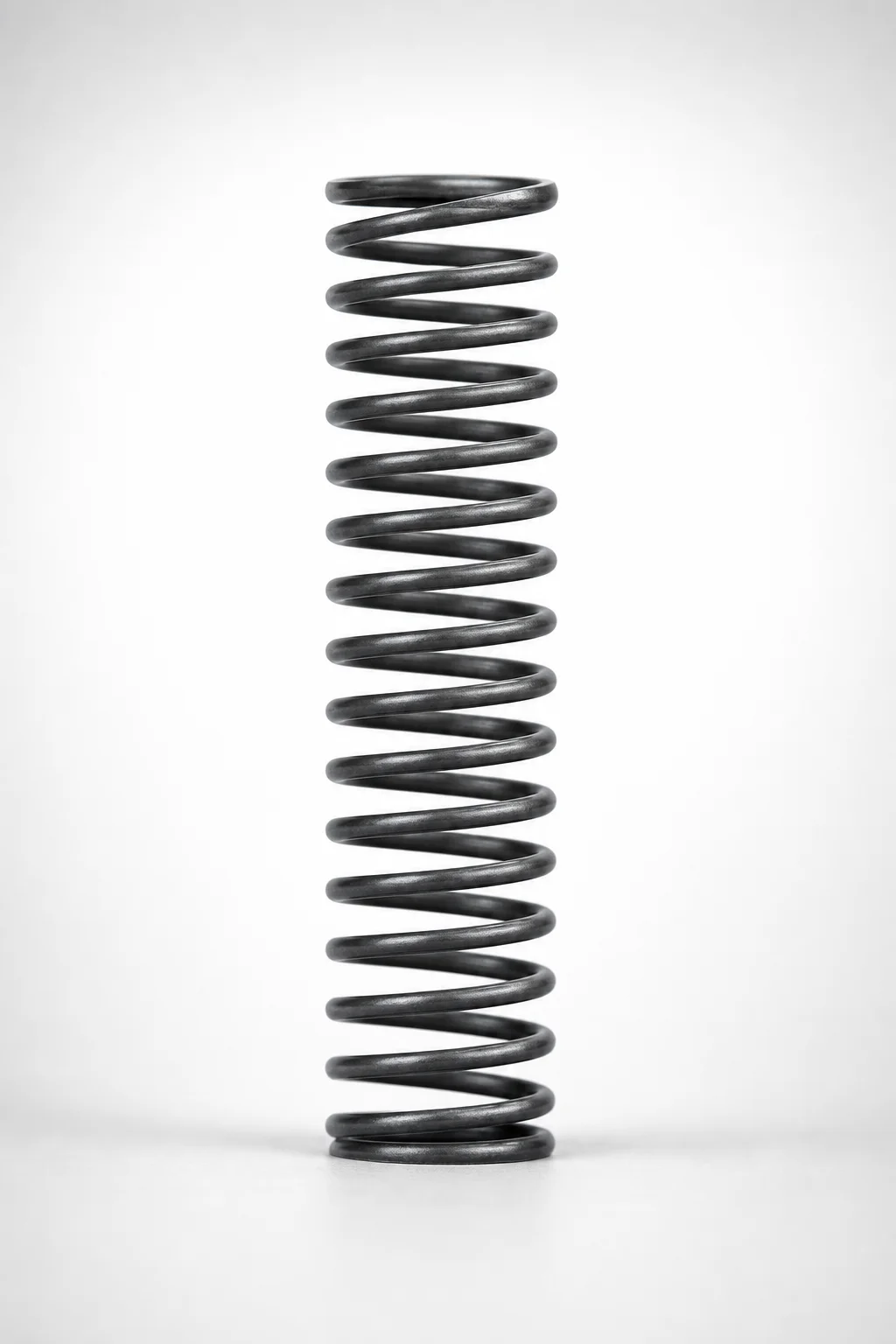
WM Series Round Wire Coil Springs 35% Deflection
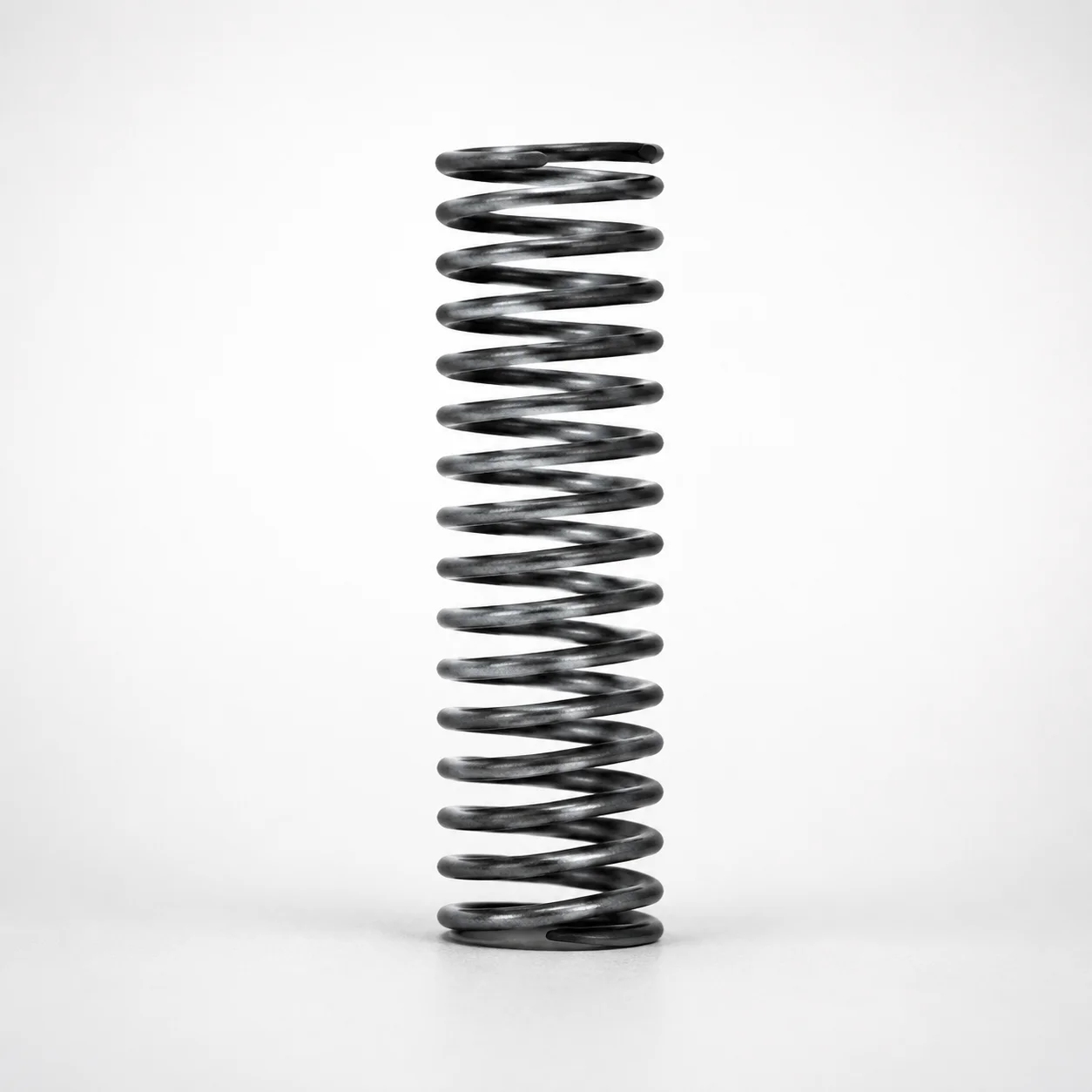
WH Series Round Wire Coil Springs - 30% Deflection
Need Custom Specifications?
Our engineering team can help with custom configurations, material selection, and volume pricing.