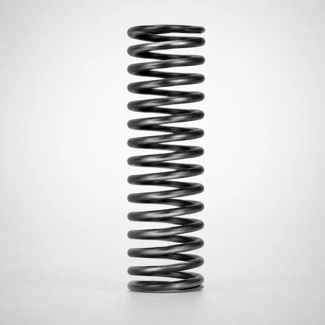
WT Series Round Wire Coil Springs 40% Deflection
Round Wire Coil Springs 40% Deflection (WT Series) are precision-made from piano wire, engineered for consistent energy absorption and stable support under varying loads. The 40% deflection design helps maintain structural integrity while protecting components in industrial mechanisms.
- 40% deflection rating delivers predictable compliance for load absorption
- Piano wire construction supports high strength and long-lasting spring performance
- Designed for controlled operation across selectable loads and spring constants
- Commonly used in mechanical systems requiring resilient return and vibration resistance
Specifications
130 configurations available
| Spring Constant (N/mm) | Allowable Deflection Ratio (%) | Maximum Load (N) | Outer Diameter D (mm) | Length L (mm) | type |
|---|---|---|---|---|---|
| 1.5 | 40 | 2.9 | 3 | 5 | - |
| 1.5 | 40 | 5.9 | 3 | 10 | - |
| 1.5 | 40 | 8.8 | 3 | 15 | - |
| 1.5 | 40 | 11.8 | 3 | 20 | - |
| 1.5 | 40 | 14.7 | 3 | 25 | - |
| 1.5 | 40 | 2.9 | 4 | 5 | - |
| 1.5 | 40 | 5.9 | 4 | 10 | - |
| 1.5 | 40 | 8.8 | 4 | 15 | - |
| 1.5 | 40 | 11.8 | 4 | 20 | - |
| 1.5 | 40 | 14.7 | 4 | 25 | - |
| 1.5 | 40 | 17.7 | 4 | 30 | - |
| 1.5 | 40 | 20.6 | 4 | 35 | - |
| 1.5 | 40 | 23.5 | 4 | 40 | - |
| 2.0 | 40 | 3.9 | 5 | 5 | - |
| 2.0 | 40 | 7.8 | 5 | 10 | - |
| 2.0 | 40 | 11.8 | 5 | 15 | - |
| 2.0 | 40 | 15.7 | 5 | 20 | - |
| 2.0 | 40 | 19.6 | 5 | 25 | - |
| 2.0 | 40 | 23.5 | 5 | 30 | - |
| 2.0 | 40 | 27.5 | 5 | 35 | - |
| 2.0 | 35 | 27.5 | 5 | 40 | - |
| 2.0 | 35 | 30.9 | 5 | 45 | - |
| 2.0 | 35 | 34.3 | 5 | 50 | - |
| 2.0 | 35 | 37.8 | 5 | 55 | - |
| 2.0 | 35 | 41.2 | 5 | 60 | - |
| 2.0 | 35 | 44.5 | 5 | 65 | - |
| 2.0 | 35 | 48.1 | 5 | 70 | - |
| 2.0 | 40 | 3.9 | 6 | 5 | - |
| 2.0 | 40 | 7.8 | 6 | 10 | - |
| 2.0 | 40 | 11.8 | 6 | 15 | - |
| 2.0 | 40 | 15.7 | 6 | 20 | - |
| 2.0 | 40 | 19.6 | 6 | 25 | - |
| 2.0 | 40 | 23.5 | 6 | 30 | - |
| 2.0 | 40 | 27.5 | 6 | 35 | - |
| 2.0 | 40 | 31.4 | 6 | 40 | - |
| 2.0 | 40 | 35.3 | 6 | 45 | - |
| 2.0 | 40 | 39.2 | 6 | 50 | - |
| 2.0 | 35 | 37.8 | 6 | 55 | - |
| 2.0 | 35 | 41.2 | 6 | 60 | - |
| 2.0 | 35 | 44.5 | 6 | 65 | - |
| 2.0 | 35 | 48.1 | 6 | 70 | - |
| 2.0 | 35 | 54.9 | 6 | 80 | - |
| 2.0 | 40 | 7.8 | 8 | 10 | - |
| 2.0 | 40 | 11.8 | 8 | 15 | - |
| 2.0 | 40 | 15.7 | 8 | 20 | - |
| 2.0 | 40 | 19.6 | 8 | 25 | - |
| 2.0 | 40 | 23.5 | 8 | 30 | - |
| 2.0 | 40 | 27.5 | 8 | 35 | - |
| 2.0 | 40 | 31.4 | 8 | 40 | - |
| 2.0 | 40 | 35.3 | 8 | 45 | - |
Product Guide
Application Scenarios+
These round wire coil springs are used as precision return and shock-absorption elements inside injection mold tooling where stable compliance is needed. The 40% deflection design helps maintain consistent force response as actuating components move, supporting repeatable operation cycle after cycle.
- Automotive connector and latch mechanisms: Fit the spring in spring-loaded ejector or latch subassemblies to damp vibration and return reliably after short stroke actuation, using the predictable 40% deflection behavior.
- Medical device housing molds: Apply in retract/return mechanisms for small core pulls or runner-related moving parts, where controlled load support reduces the risk of bounce and improves dimensional repeatability.
- General industrial automation tooling: Use for resilient stops or force-limiting fixtures; the piano wire construction supports high strength needed to sustain load support under varying duty.
Material & Process Details+
The WT series springs are manufactured from piano wire, a high-carbon steel known for high tensile strength and excellent fatigue performance—ideal for maintaining stable spring force under cyclic loading. Piano wire is typically produced via controlled cold working to achieve the required round-wire geometry and consistent spring response.
- Heat treatment: Springs are commonly supplied in a pre-formed, hardened condition suitable for load support; exact heat-treatment state is not specified in the provided data.
- Performance trade-off: High strength and wear/fatigue resistance improve load stability, while toughness must be managed through proper forming and controlled stresses to avoid premature microcracking.
- Available variants: This listing focuses on deflection ratio variants (40% and also 35% noted), enabling tuning of compliance versus load capacity without changing the core piano-wire material approach.
For wear-intensive environments, consider corrosion control and proper spring seating surfaces in the tooling design to preserve fatigue life.
Sizing & Selection Guide+
Select the spring by matching deflection ratio, load requirement, and geometry to your mold’s mechanism stroke and force envelope. Start with the required deflection ratio: this variant is specified at 40% allowable deflection ratio.
- Determine required stroke: For a target working displacement, ensure the expected deflection falls within the chosen ratio (40% for this WT configuration; 35% is available per provided specs).
- Match length L (mm): Choose the installed free/working length within 5 to 80 mm, accounting for how the spring seats in the mold (end compression and guide constraints).
- Match outer diameter D (mm): Select D = 3 to 27 mm so the spring clears surrounding components and fits within the spring pocket while preventing side loading.
- Verify spring constant (N/mm): Use the provided spring constant options 1.5, 2.0, 3.9 N/mm to meet your force/deflection target; confirm the resulting load stays below the maximum load 2.9 ~ 125.5 N for your chosen size.
Because exact tolerance values are not provided, maintain design clearance and ensure the spring seats squarely to limit stress concentration and fit-induced binding.
Frequently Asked Questions
How do I choose between the WT series 40% vs 35% allowable deflection ratio for mold return mechanisms?+
What spring constant options (N/mm) are available, and how should I relate them to actuator force in the mold design?+
How do I select the correct outer diameter D and length L (mm) range to avoid coil bind and side loading?+
Can this WT series spring support the load levels required by my ejector return circuit?+
What is the primary material basis for fatigue resistance in these coil springs used in cyclic injection mold tooling?+
Related Products
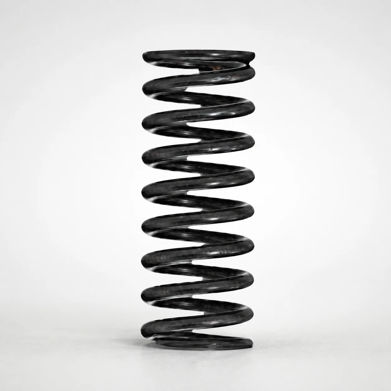
Round Wire Coil Springs - 75% Deflection, WY Series
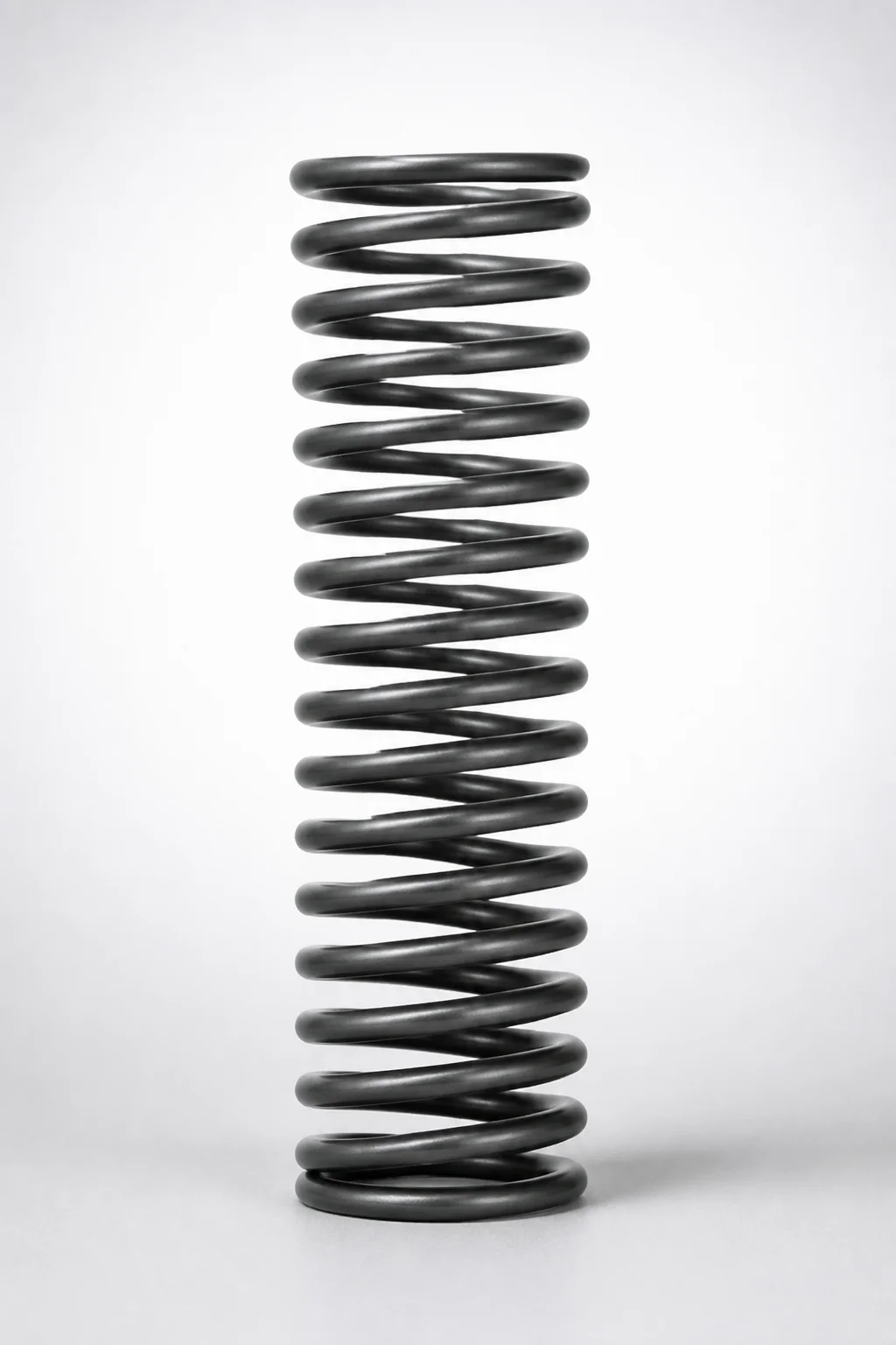
WR Series Round Wire Coil Springs 60% Deflection
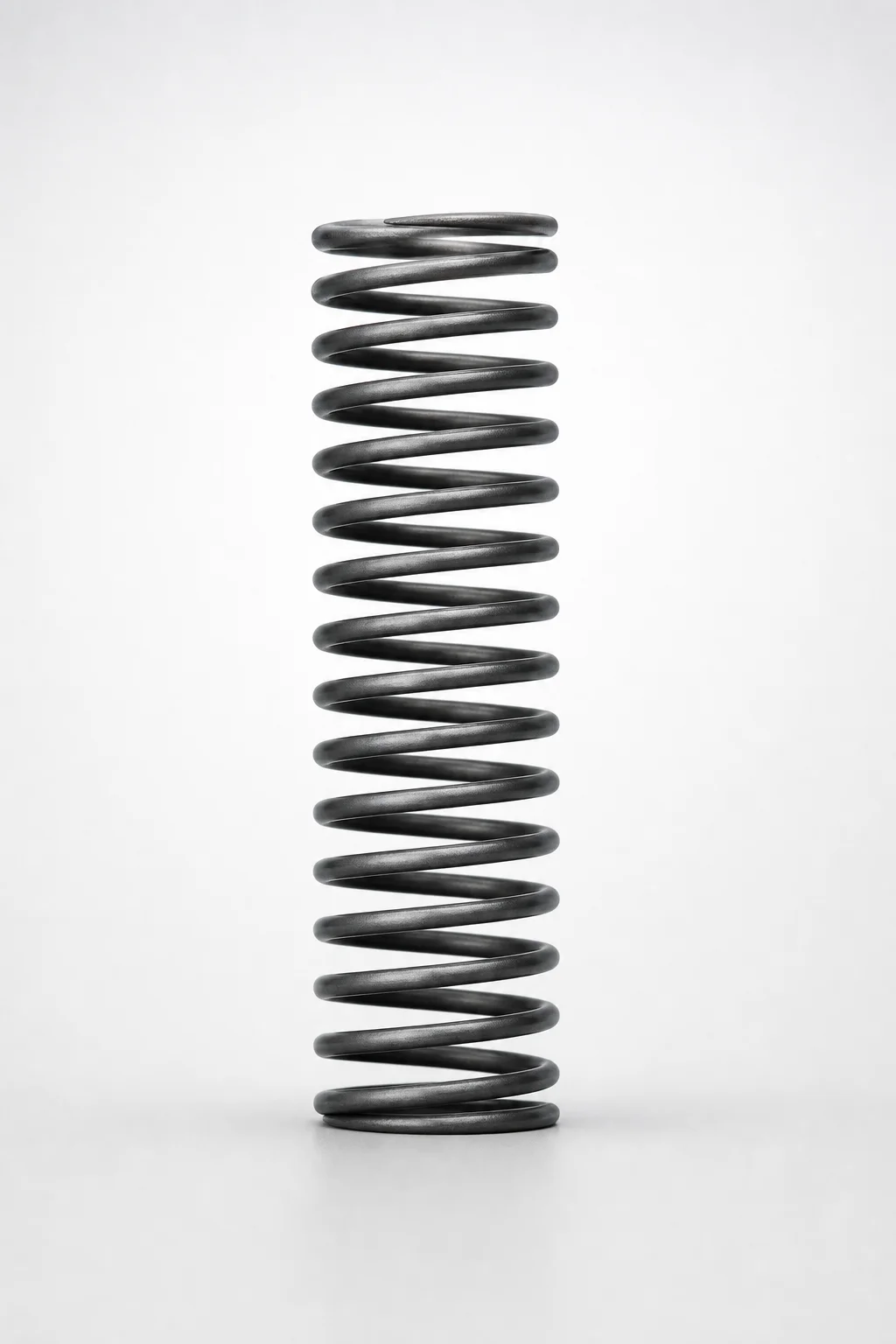
Round Wire Coil Springs - 45% Deflection WF Series
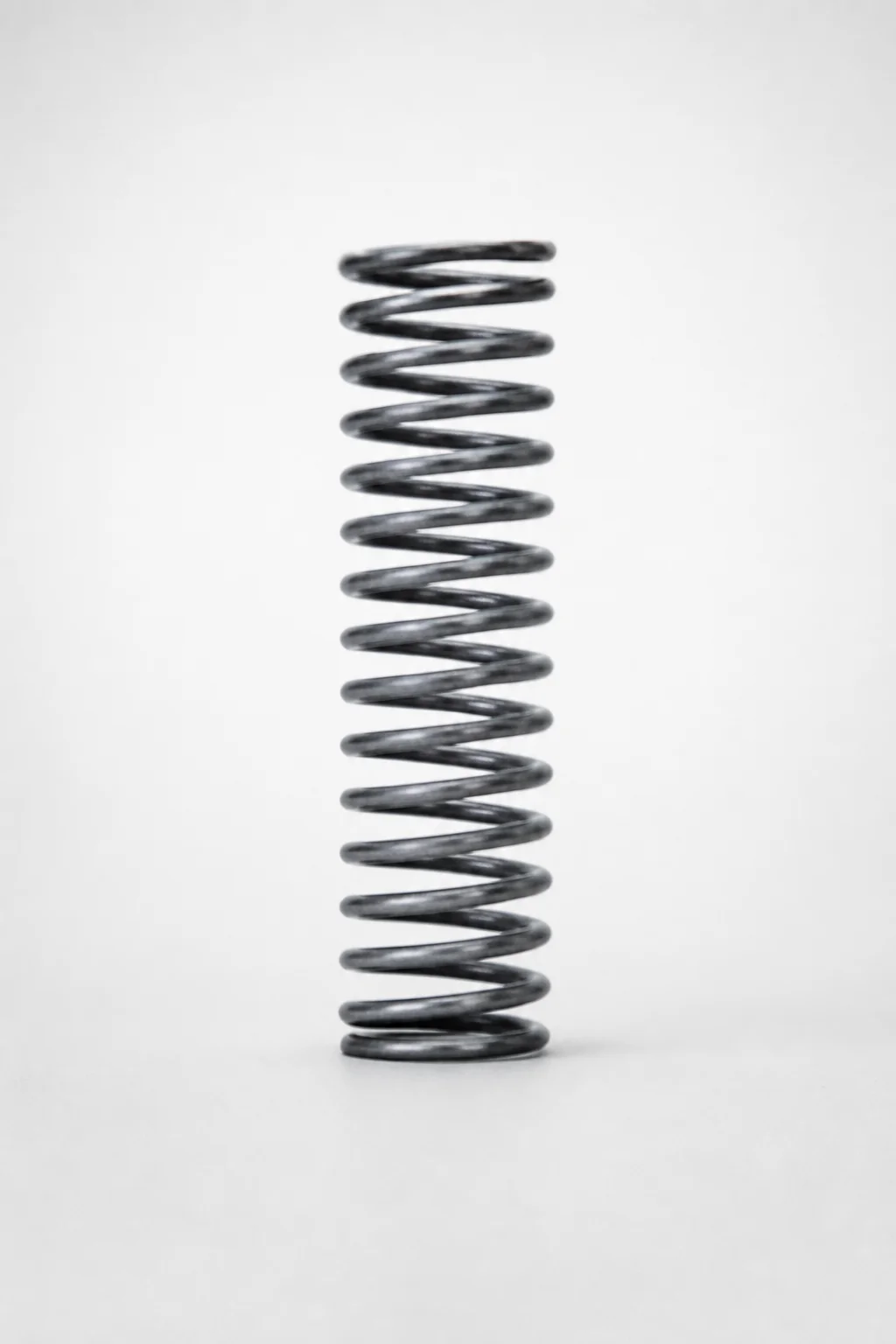
Piano Wire Round Wire Coil Springs - 40% Deflection, WL Series
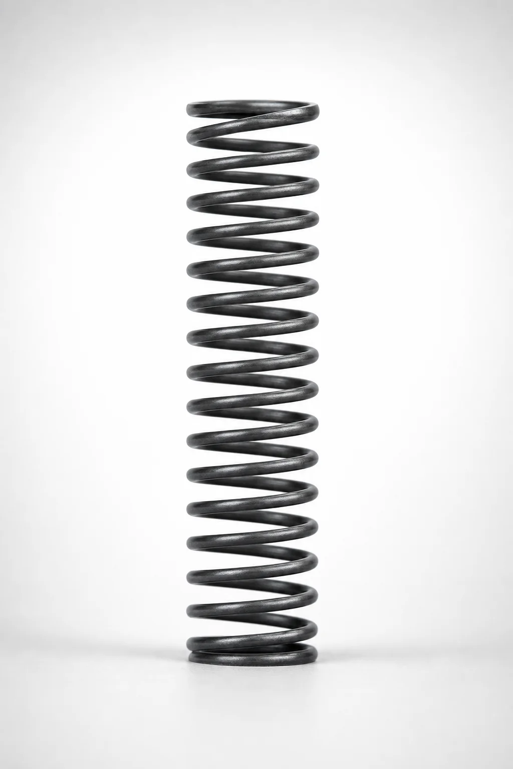
WM Series Round Wire Coil Springs 35% Deflection
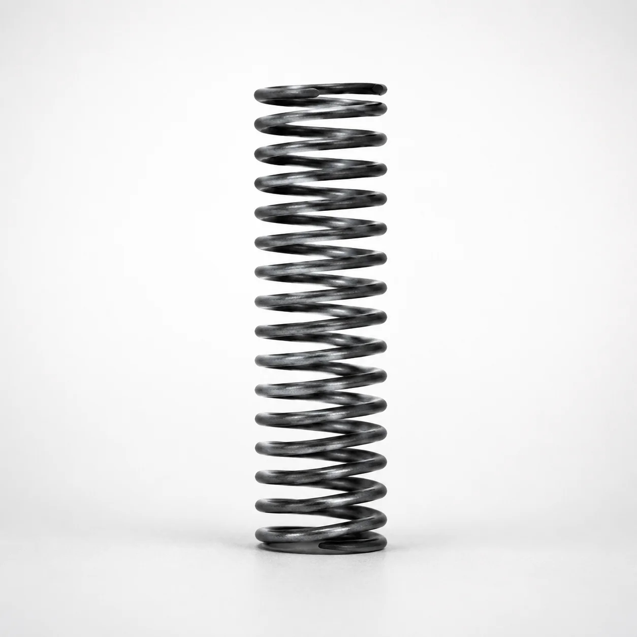
WH Series Round Wire Coil Springs - 30% Deflection
Need Custom Specifications?
Our engineering team can help with custom configurations, material selection, and volume pricing.