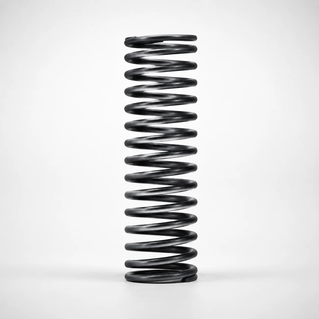
Round Wire Coil Springs - 25% Deflection WB Series
Round Wire Coil Springs - 25% Deflection WB Series provide predictable force behavior for applications that require controlled compliance. Their WB type construction supports consistent performance across a wide selectable load range.
- Designed for 25% deflection to match controlled spring response needs
- Selectable spring constant options to fit varying force requirements
- Supports a wide maximum load range for stable press and assembly action
- WB type round-wire coil form for dependable fit in standard spring designs
Specifications
169 configurations available
| Spring Constant (N/mm) | Maximum Load (N) | Outer Diameter D (mm) | Length L (mm) | type |
|---|---|---|---|---|
| 3.9 | 4.9 | 3 | 5 | - |
| 3.9 | 9.8 | 3 | 10 | - |
| 3.9 | 14.7 | 3 | 15 | - |
| 3.9 | 19.6 | 3 | 20 | - |
| 3.9 | 24.5 | 3 | 25 | - |
| 3.9 | 29.4 | 3 | 30 | - |
| 3.9 | 34.3 | 3 | 35 | - |
| 3.9 | 39.2 | 3 | 40 | - |
| 4.9 | 5.9 | 4 | 5 | - |
| 4.9 | 12.3 | 4 | 10 | - |
| 4.9 | 18.1 | 4 | 15 | - |
| 4.9 | 24.5 | 4 | 20 | - |
| 4.9 | 30.4 | 4 | 25 | - |
| 4.9 | 36.8 | 4 | 30 | - |
| 4.9 | 43.1 | 4 | 35 | - |
| 4.9 | 49.0 | 4 | 40 | - |
| 4.9 | 55.4 | 4 | 45 | - |
| 4.9 | 61.3 | 4 | 50 | - |
| 9.8 | 12.7 | 5 | 5 | - |
| 9.8 | 24.5 | 5 | 10 | - |
| 9.8 | 37.3 | 5 | 15 | - |
| 9.8 | 49.0 | 5 | 20 | - |
| 9.8 | 61.8 | 5 | 25 | - |
| 9.8 | 73.5 | 5 | 30 | - |
| 9.8 | 86.3 | 5 | 35 | - |
| 9.8 | 98.1 | 5 | 40 | - |
| 9.8 | 110.8 | 5 | 45 | - |
| 9.8 | 122.6 | 5 | 50 | - |
| 9.8 | 135.3 | 5 | 55 | - |
| 9.8 | 147.1 | 5 | 60 | - |
| 9.8 | 159.8 | 5 | 65 | - |
| 9.8 | 171.6 | 5 | 70 | - |
| 9.8 | 12.7 | 6 | 5 | - |
| 9.8 | 24.5 | 6 | 10 | - |
| 9.8 | 37.3 | 6 | 15 | - |
| 9.8 | 49.0 | 6 | 20 | - |
| 9.8 | 61.8 | 6 | 25 | - |
| 9.8 | 73.5 | 6 | 30 | - |
| 9.8 | 86.3 | 6 | 35 | - |
| 9.8 | 98.1 | 6 | 40 | - |
| 9.8 | 110.8 | 6 | 45 | - |
| 9.8 | 122.6 | 6 | 50 | - |
| 9.8 | 135.3 | 6 | 55 | - |
| 9.8 | 147.1 | 6 | 60 | - |
| 9.8 | 159.8 | 6 | 65 | - |
| 9.8 | 171.6 | 6 | 70 | - |
| 9.8 | 196.1 | 6 | 80 | - |
| 9.8 | 24.5 | 8 | 10 | - |
| 9.8 | 37.3 | 8 | 15 | - |
| 9.8 | 49.0 | 8 | 20 | - |
Product Guide
Application Scenarios+
Round-wire coil springs in injection mold tooling are commonly used as return and compliance elements where repeatable force is needed under cycling loads. This 25% deflection WB-style spring is well suited for ejector or stripper plate return, helping maintain stable contact and predictable rebound when actuated by cam or mechanical linkages.
In automated handling and clamping assemblies, the ability to select a spring constant (3.9, 4.9, 9.8, 19.6, 29.4 N/mm) supports controlled compliance for press-fit, assembly, and load-limited mechanisms. The specified maximum load range (4.9 to 735.5 N) helps prevent over-compression in tight tool space.
They are also used in industrial fixture systems inside production cells where limited deflection is required for consistent positioning. The spring’s round-wire, WB construction supports dependable function in standard spring seats while the 25% design target aligns force response with controlled motion profiles.
Material & Process Details+
The provided specifications describe spring geometry and load/deflection characteristics, but no steel grade, hardness (HRC), or heat-treatment condition is included in the input data. For accurate material selection, confirm the actual spring material (e.g., commonly used spring steels), then validate the heat-treatment state such as quench and temper, shot peening, or other spring-specific finishing required for fatigue resistance.
When selecting a spring steel grade for tool use, engineers typically balance wear resistance against toughness and fatigue life. Higher-hardness states (often specified as HRC on the datasheet) can increase resistance to set and surface wear, but may reduce toughness if overly aggressive; the correct trade-off depends on the cycling load and environment.
- Need confirmation: steel grade/standard and hardness aren’t specified in the current data.
- Process to verify: heat treatment and any surface treatments that support long-cycle fatigue performance.
Sizing & Selection Guide+
To select the correct spring for your mold or industrial assembly, match both free dimensions and force characteristics to the available space and required compliance. Start with outer diameter D in the range 3–27 mm and length L from 5–100 mm. Ensure the spring can move through its stroke without interference in the spring pocket, guide, or retainer.
Next, choose the required spring constant based on the force you need at the design deflection. This WB series is specified around 25% deflection, so use your target deflection condition to select the corresponding stiffness options: 3.9, 4.9, 9.8, 19.6, 29.4 N/mm.
- Check maximum load: select a variant whose maximum load (4.9 to 735.5 N) is above your peak operating force with margin to avoid overstress.
- Tolerance/fit: validate clearances for D and L against your retainer bore and pocket depth; the input data provides ranges only, so confirm the exact dimensional tolerances from the product drawing.
- Configurable vs. fixed: D, L, spring constant, and maximum load are selectable within the given ranges.
Frequently Asked Questions
How do I choose the correct spring constant for the WB series’s 25% deflection target?+
What dimensional limits should I use when designing a spring pocket or seat for this round-wire spring?+
How do I ensure the spring won’t be overstressed in my mold mechanism?+
Can I use this spring in both tooling return functions and industrial clamping/positioning devices?+
Related Products
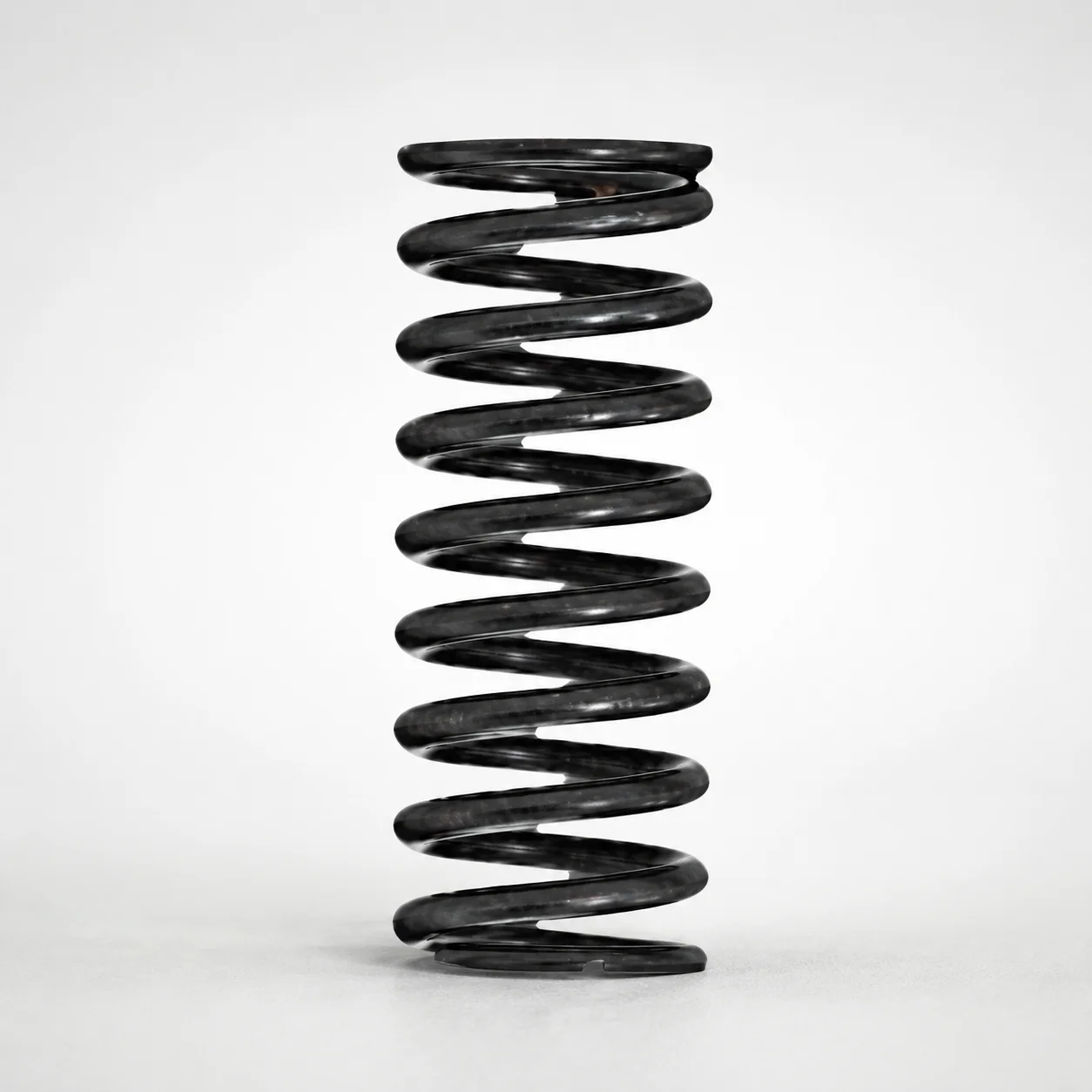
Round Wire Coil Springs - 75% Deflection, WY Series
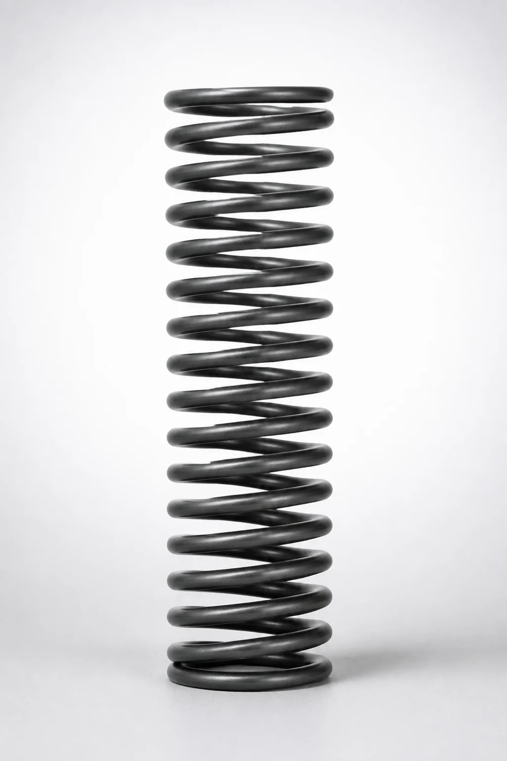
WR Series Round Wire Coil Springs 60% Deflection
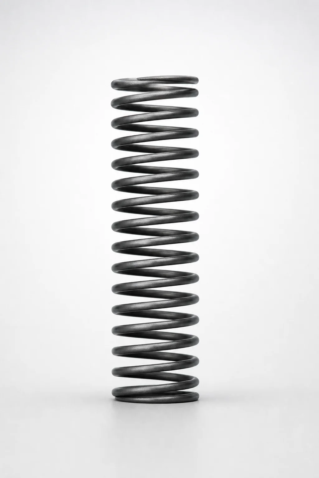
Round Wire Coil Springs - 45% Deflection WF Series
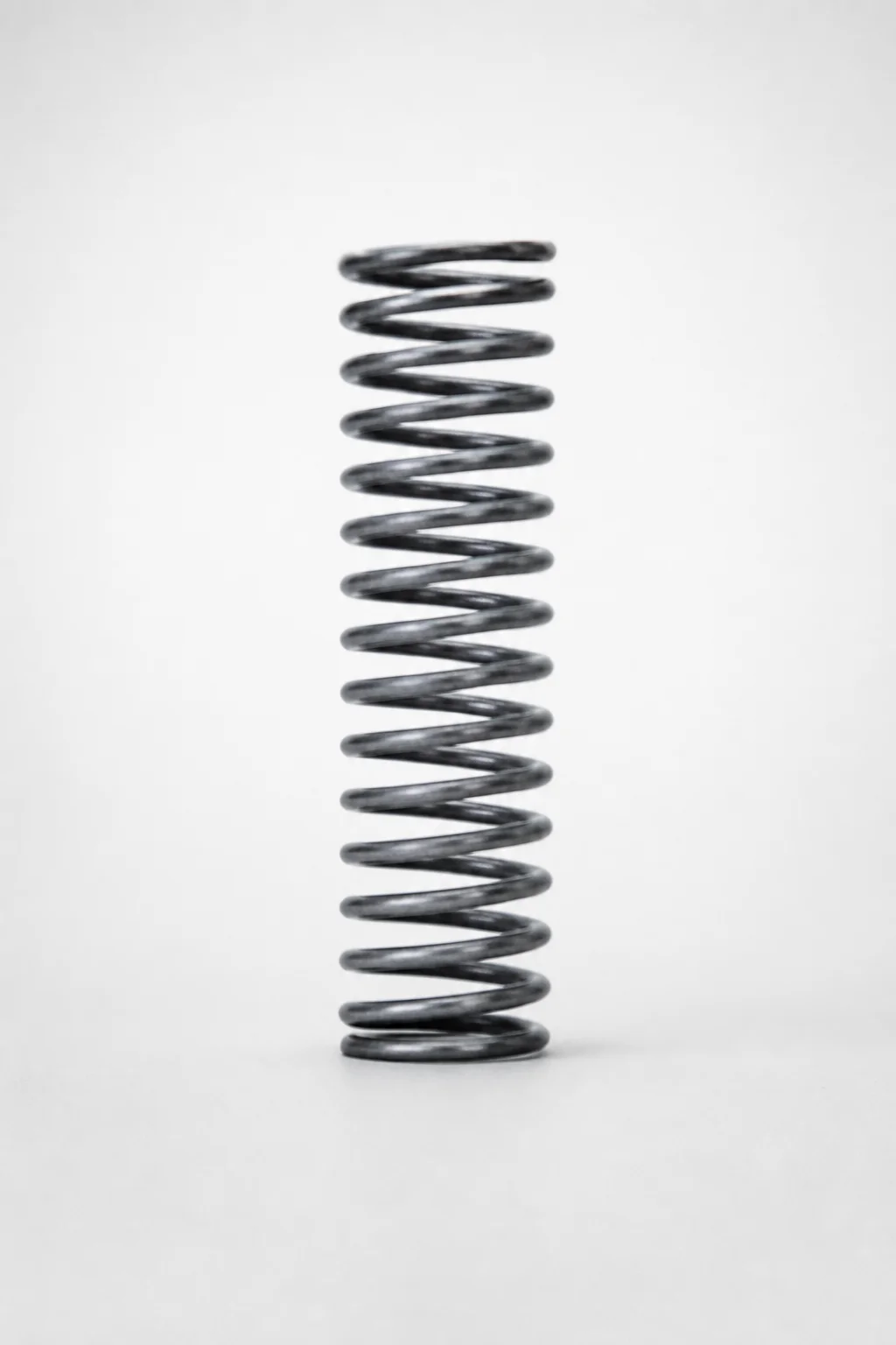
Piano Wire Round Wire Coil Springs - 40% Deflection, WL Series
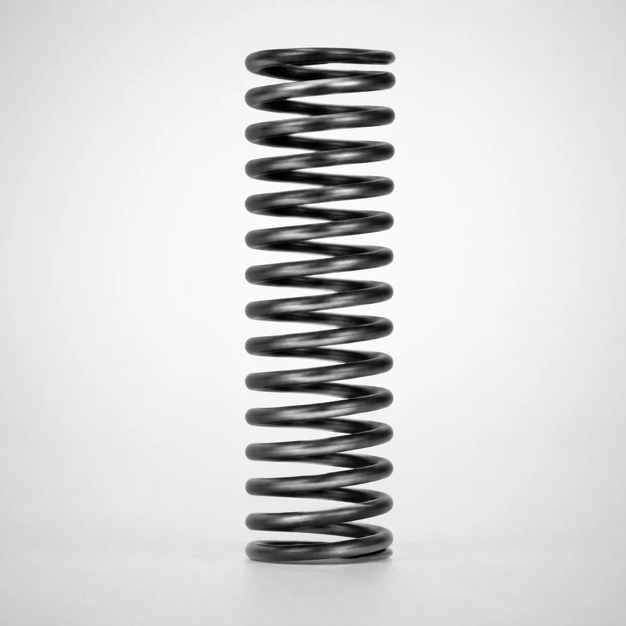
WT Series Round Wire Coil Springs 40% Deflection
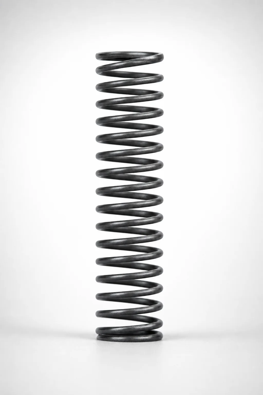
WM Series Round Wire Coil Springs 35% Deflection
Need Custom Specifications?
Our engineering team can help with custom configurations, material selection, and volume pricing.