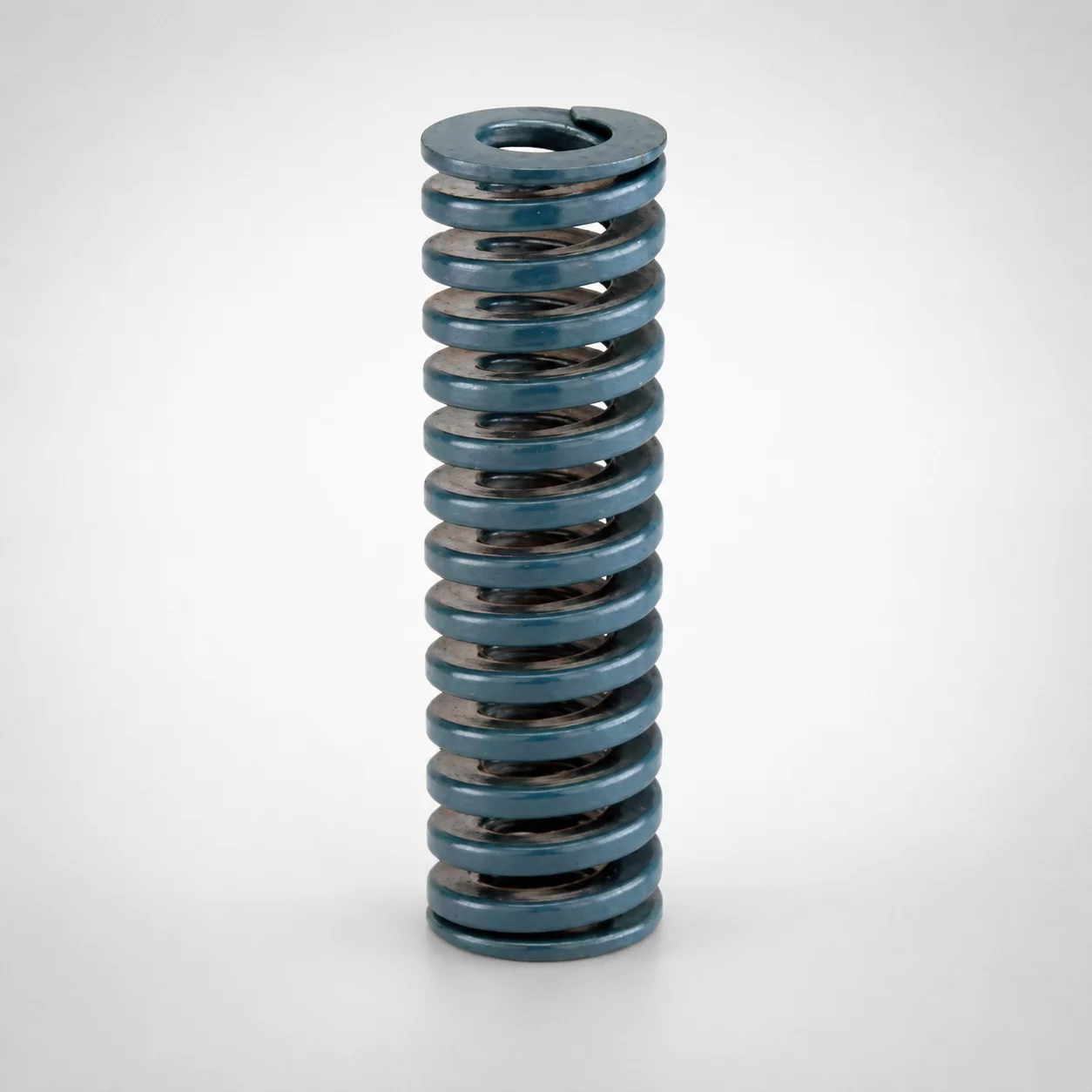
JIS Standard Medium Load Round Wire Die Spring - 37.5% Deflection
Medium load round wire die spring (DieMax XL™) is engineered for stable press performance with an 37.5% allowable deflection ratio, helping maintain consistent die opening force throughout forming cycles.
- Medium load spring rate supports controlled material flow in die operations
- Blue-inch format for reliable fit in standard die spring setups
- Designed around 37.5% allowable deflection for predictable deflection under load
- Suitable for general die tooling where medium-load return spring consistency matters
Specifications
30 configurations available
| Outer Diameter D (in) | Length L (in) | d (Inner diameter) (in) |
|---|---|---|
| 3/8" | 3/4" | 3/16" |
| 3/8" | 1" | 3/16" |
| 3/8" | 1-1/4" | 3/16" |
| 3/8" | 1-1/2" | 3/16" |
| 3/8" | 1-3/4" | 3/16" |
| 3/8" | 2" | 3/16" |
| 3/8" | 2-1/2" | 3/16" |
| 3/8" | 3" | 3/16" |
| 3/8" | 12" | 3/16" |
| 1/2" | 3/4" | 9/32" |
| 1/2" | 1" | 9/32" |
| 1/2" | 1-1/4" | 9/32" |
| 1/2" | 1-1/2" | 9/32" |
| 1/2" | 1-3/4" | 9/32" |
| 1/2" | 2" | 9/32" |
| 1/2" | 2-1/2" | 9/32" |
| 1/2" | 3" | 9/32" |
| 1/2" | 3-1/2" | 9/32" |
| 1/2" | 12" | 9/32" |
| 5/8" | 3/4" | 11/32" |
| 5/8" | 1" | 11/32" |
| 5/8" | 1-1/4" | 11/32" |
| 5/8" | 1-1/2" | 11/32" |
| 5/8" | 1-3/4" | 11/32" |
| 5/8" | 2" | 11/32" |
| 5/8" | 2-1/2" | 11/32" |
| 5/8" | 3" | 11/32" |
| 5/8" | 3-1/2" | 11/32" |
| 5/8" | 4" | 11/32" |
| 5/8" | 12" | 11/32" |
Product Guide
Application Scenarios+
This medium-load round wire die spring is used in injection mold and die-set tooling to provide repeatable cavity return force and stable die opening behavior across production cycles.
- Automotive connector and bracket tooling: When inserts or slides must return consistently after each molding shot, the 37.5% allowable deflection ratio helps maintain a predictable force curve within the medium-load range, reducing variability in part ejection timing.
- Consumer electronics housings with tight cycle control: For dies that require controlled material flow and consistent venting/return motion, the round-wire design supports smooth engagement and repeatability in standard die spring pockets.
- General forming and die tooling: Use this variant when your spring stack or die spring cavity is optimized for medium loading and you want predictable deflection under load without oversizing the spring.
Its blue-inch format and medium-load deflection allowance make it well suited for common die spring assemblies where dimensional compatibility and stable force are critical.
Material & Process Details+
The provided data identifies the spring as a JIS standard medium load round wire die spring (DieMax XL™), but it does not specify a steel grade, hardness (HRC), heat treatment, or plating/coating. Therefore, material-property claims such as exact wear resistance or quenched-and-tempered hardness cannot be confirmed from the available specifications.
What can be stated from the documentation is the performance basis: the design is optimized around an allowable deflection ratio of 37.5%, which directly affects the load–deflection behavior and the required spring toughness/elastic integrity for medium-load cycling.
- Material state: Not specified in the supplied parameters (e.g., pre-hardened vs. quenched & tempered, nitrided).
- Wear vs. toughness trade-off: Not specified; selection should be verified with the manufacturer documentation for the required cycle life and operating environment.
- Multiple materials: Not listed for this part in the provided data.
Sizing & Selection Guide+
Select the die spring dimensions to match the available space and the required deflection range in your mold’s die return or ejection mechanism. This spring is specified by outer diameter D, inner diameter d, and length L.
- Outer Diameter D (in): choose from 3/8, 1/2, or 5/8 to fit the die spring pocket or guide clearance.
- Inner Diameter d (in): choose from 3/16, 9/32, or 11/32 to clear the locating post/rod and ensure proper alignment.
- Length L (in): select from 1 ~ 12 based on free height and compressed stack height in the closed die condition.
Ensure the working stroke stays within the design’s 37.5% allowable deflection ratio to avoid loss of force predictability. If your assembly has tight constraints, confirm how your pocket dimensions/tolerances relate to the selected D and d; the spring must seat without binding and maintain concentricity through cycling.
Frequently Asked Questions
How do I verify that my spring working stroke stays within the 37.5% allowable deflection ratio for this die spring?+
Which dimension should I prioritize for fit into a standard die spring pocket: outer diameter D or inner diameter d?+
What free length L should I choose when my mold’s compressed stack height is fixed?+
Can this spring be used for higher-load applications, or is it restricted to medium-load die tooling?+
Does DANLY IEM’s DieMax XL™ blue-inch format imply any specific standard for dimensional compatibility?+
Related Products
JIS Standard Chrome Silicon Medium Duty Die Spring 60% Deflection
JIS Standard Chrome Silicon Medium Duty Die Spring - 50% Deflection
JIS Standard Chrome Silicon Steel Medium Duty Die Spring - 40% Deflection
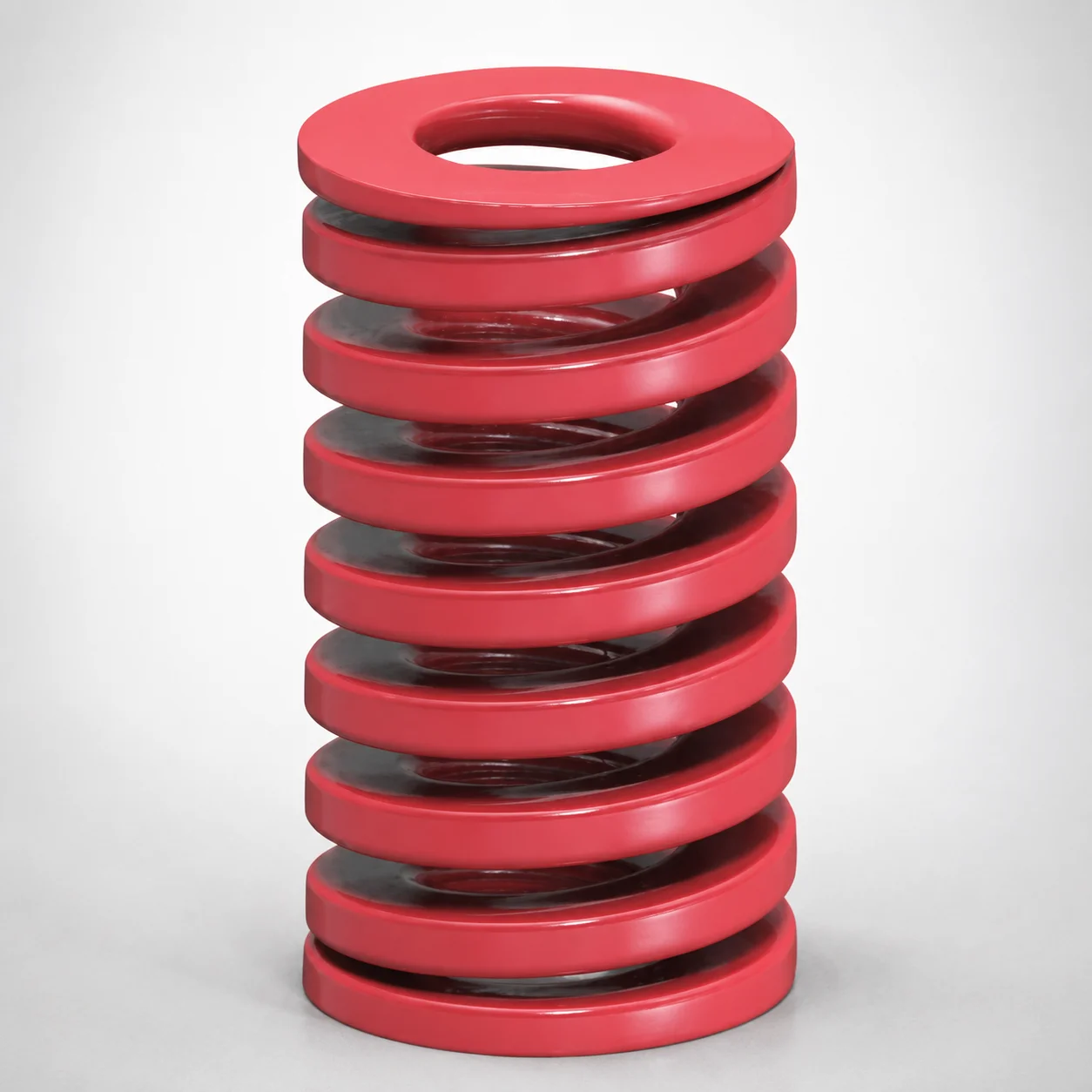
JIS Standard Medium Duty Die Spring 32% Deflection Chrome Silicon Coil Springs
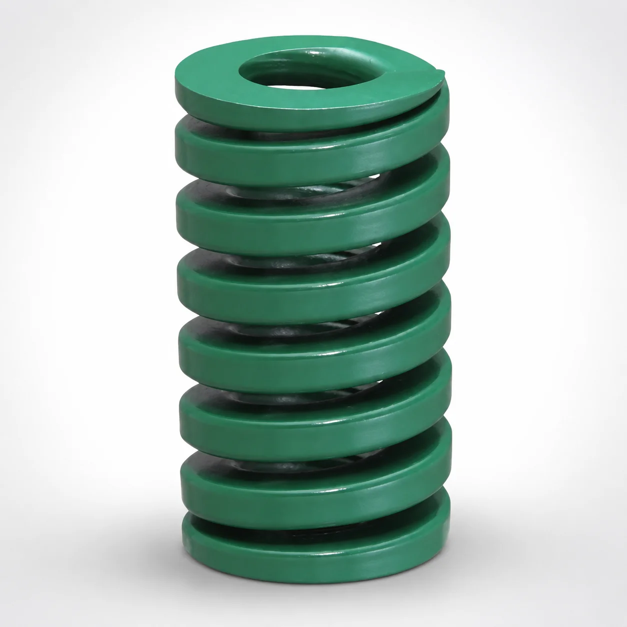
JIS Standard Heavy Duty Die Spring 24% Deflection
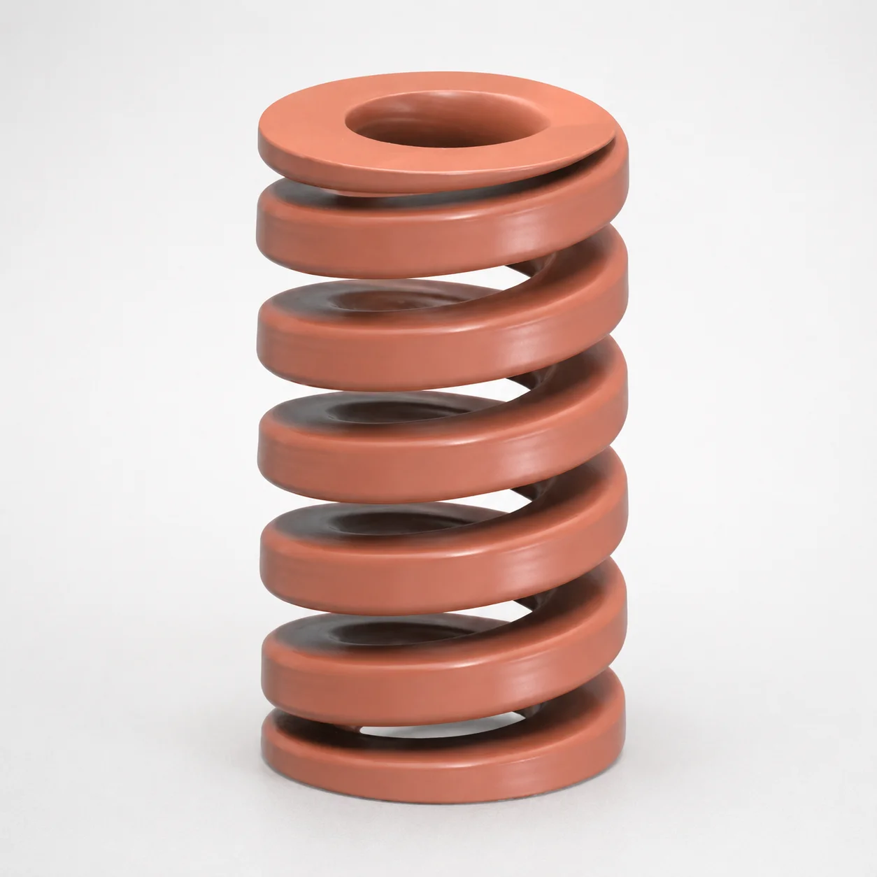
JIS Standard Chrome Silicon Oil-Tempered Wire Heavy Duty Die Spring 20% Deflection
Need Custom Specifications?
Our engineering team can help with custom configurations, material selection, and volume pricing.