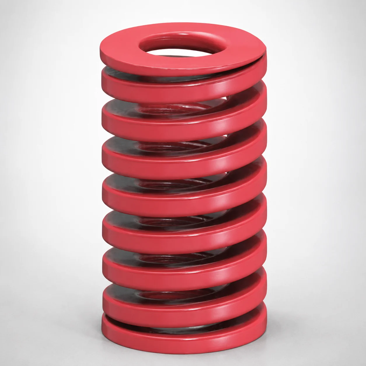
JIS Standard Medium Duty Die Spring 32% Deflection Chrome Silicon Coil Springs
Medium Duty Die Spring 32% Deflection (Chrome Silicon) is engineered for dependable spring return under medium load die functions, delivering consistent deflection characteristics throughout production. Built for long service life in demanding mechanical cycles.
- Medium load coil spring design with 32% deflection for stable performance
- Chrome silicon oil-tempered wire material for durability and fatigue resistance
- Option for coated or no coating to match corrosion control requirements
- Compatible with JIS die spring standards for streamlined procurement and fit
Specifications
526 configurations available
| Maximum Load (N) | Outer Diameter D (mm) | Length L (mm) | Coating Removal | type |
|---|---|---|---|---|
| 98 | 6 | 15 | No coating | - |
| 98 | 6 | 20 | No coating | - |
| 98 | 6 | 25 | No coating | - |
| 98 | 6 | 30 | No coating | - |
| 98 | 6 | 35 | No coating | - |
| 98 | 6 | 40 | No coating | - |
| 98 | 6 | 45 | No coating | - |
| 98 | 6 | 50 | No coating | - |
| 98 | 6 | 55 | No coating | - |
| 98 | 6 | 60 | No coating | - |
| 137 | 8 | 10 | No coating | - |
| 137 | 8 | 15 | No coating | - |
| 137 | 8 | 20 | No coating | - |
| 137 | 8 | 25 | No coating | - |
| 137 | 8 | 30 | No coating | - |
| 137 | 8 | 35 | No coating | - |
| 137 | 8 | 40 | No coating | - |
| 137 | 8 | 45 | No coating | - |
| 137 | 8 | 50 | No coating | - |
| 137 | 8 | 55 | No coating | - |
| 137 | 8 | 60 | No coating | - |
| 137 | 8 | 65 | No coating | - |
| 137 | 8 | 70 | No coating | - |
| 137 | 8 | 75 | No coating | - |
| 137 | 8 | 80 | No coating | - |
| 196 | 10 | 10 | No coating | - |
| 196 | 10 | 15 | No coating | - |
| 196 | 10 | 20 | No coating | - |
| 196 | 10 | 25 | No coating | - |
| 196 | 10 | 30 | No coating | - |
| 196 | 10 | 35 | No coating | - |
| 196 | 10 | 40 | No coating | - |
| 196 | 10 | 45 | No coating | - |
| 196 | 10 | 50 | No coating | - |
| 196 | 10 | 55 | No coating | - |
| 196 | 10 | 60 | No coating | - |
| 196 | 10 | 65 | No coating | - |
| 196 | 10 | 70 | No coating | - |
| 196 | 10 | 75 | No coating | - |
| 196 | 10 | 80 | No coating | - |
| 196 | 10 | 90 | No coating | - |
| 284 | 12 | 15 | No coating | - |
| 284 | 12 | 20 | No coating | - |
| 284 | 12 | 25 | No coating | - |
| 284 | 12 | 30 | No coating | - |
| 284 | 12 | 35 | No coating | - |
| 284 | 12 | 40 | No coating | - |
| 284 | 12 | 45 | No coating | - |
| 284 | 12 | 50 | No coating | - |
| 284 | 12 | 55 | No coating | - |
Product Guide
Application Scenarios+
This medium-duty die spring is used inside injection mold tooling to provide reliable return force for mechanical slides, ejector pins, and lifters during parting and cycle reset. Its 32% deflection design targets stable force-displacement behavior in medium-load die stations, helping maintain consistent closure timing and repeatability over high cycle counts.
- Automotive interior/exterior trim molds: Suitable for ejector or stripper mechanisms where frequent cycling demands fatigue resistance; the chrome silicon wire supports dependable return without large force drift.
- Appliance and housings injection molds: Works well for moderate-load die return needs in multi-cavity tools, especially when corrosion exposure varies across cavity layouts.
- General die spring applications (JIS standardized builds): The JIS medium-duty alignment supports streamlined procurement and fit planning when replacing or upgrading tooling components.
Choose the coated option when corrosion control is required; select no coating when a downstream coating or protective treatment is already specified by the mold build plan.
Material & Process Details+
The spring wire is chrome silicon (Chrome Silicon steel), selected for good fatigue performance under cyclic bending and for its durability in die environments. The product description indicates the wire is oil-tempered, which supports stable spring behavior by balancing strength and elastic response for medium-duty applications.
- Hardness & wear trade-off: Coil die springs prioritize fatigue life and toughness over extreme surface wear hardness; higher hardness can reduce fatigue tolerance if over-embrittled, so spring steel heat treatment is optimized for controlled strength rather than abrasive wear.
- Heat treatment state: Oil-tempered chrome silicon spring wire is used to achieve the required elastic properties for consistent deflection performance at the specified 32% deflection condition.
- Coating options: Available as Coated or No coating to match corrosion requirements without changing the core spring metallurgy.
If your mold operates in humid or wash-down conditions, the coated variant typically provides better corrosion resistance than bare steel while maintaining the same spring steel base properties.
Sizing & Selection Guide+
To select the correct die spring, match the deflection load requirement and the space envelope of your return mechanism. This series covers Maximum Load (N): 98 ~ 8330, Outer Diameter D: 6 ~ 70 mm, and Length L: 10 ~ 350 mm.
- Step 1—Check required return force: Choose a spring within the 98–8330 N maximum load range for your slide/ejector return design, using the tool’s cycle load assumptions at the intended 32% deflection operating condition.
- Step 2—Verify dimensional fit: Confirm the outer diameter D (6–70 mm) clears the guide, spring pocket bore, and any adjacent hardware at full compression.
- Step 3—Set installed length constraints: Use length L (10–350 mm) to satisfy your free length vs. compressed stroke requirements while preventing coil bind.
For compatibility in standardized die spring assemblies, follow the JIS medium-duty geometry expectations of your existing tooling. If you are replacing an installed spring, measure the available spring pocket dimensions to ensure the selected D and L provide the required working stroke; tolerance details are controlled by the JIS-based procurement/fit plan.
Frequently Asked Questions
How do I choose the right spring from the maximum load range (98–8330 N) for a 32% deflection return mechanism?+
What outer diameter (D) range is available, and how do I prevent interference in the spring pocket?+
When should I specify the coated option versus no coating for die return springs?+
How do I match the spring length (L = 10–350 mm) to my stroke to avoid coil bind?+
Is this die spring compatible with JIS medium-duty die spring standards for replacements?+
Related Products
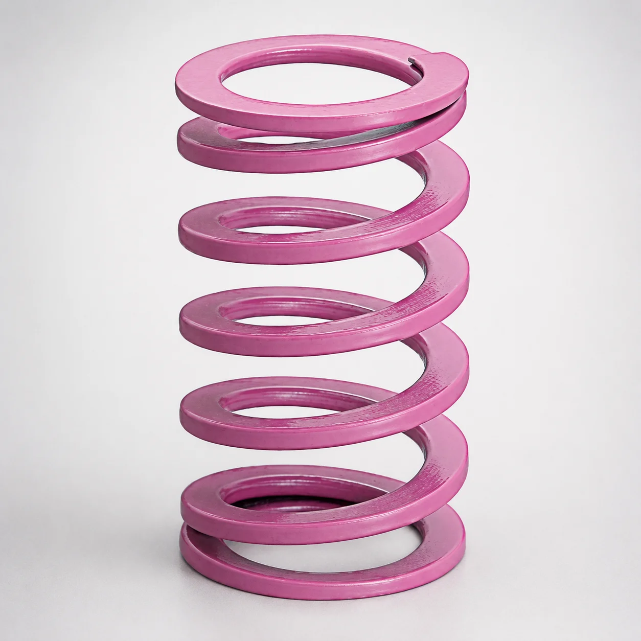
JIS Standard Chrome Silicon Medium Duty Die Spring 60% Deflection
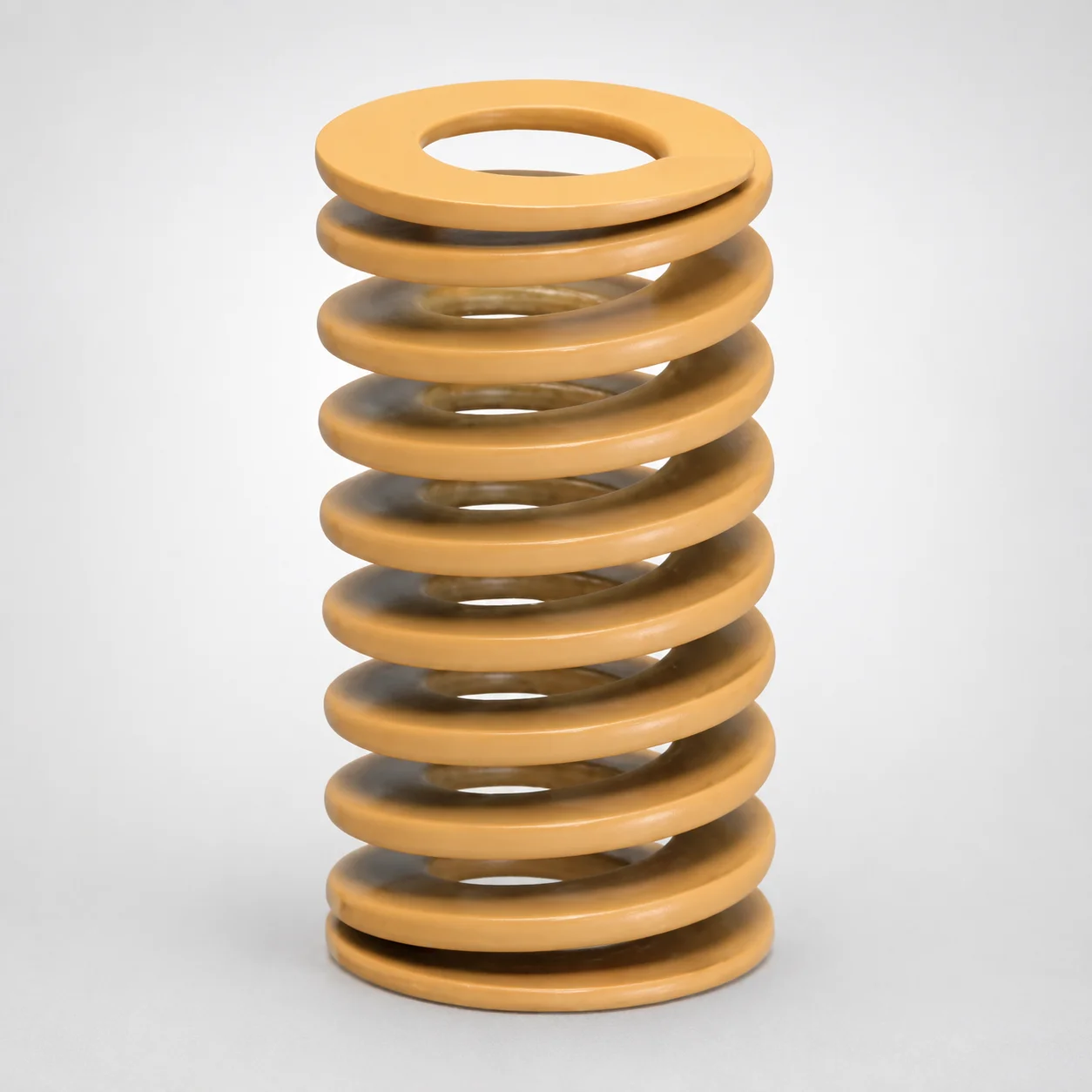
JIS Standard Chrome Silicon Medium Duty Die Spring - 50% Deflection
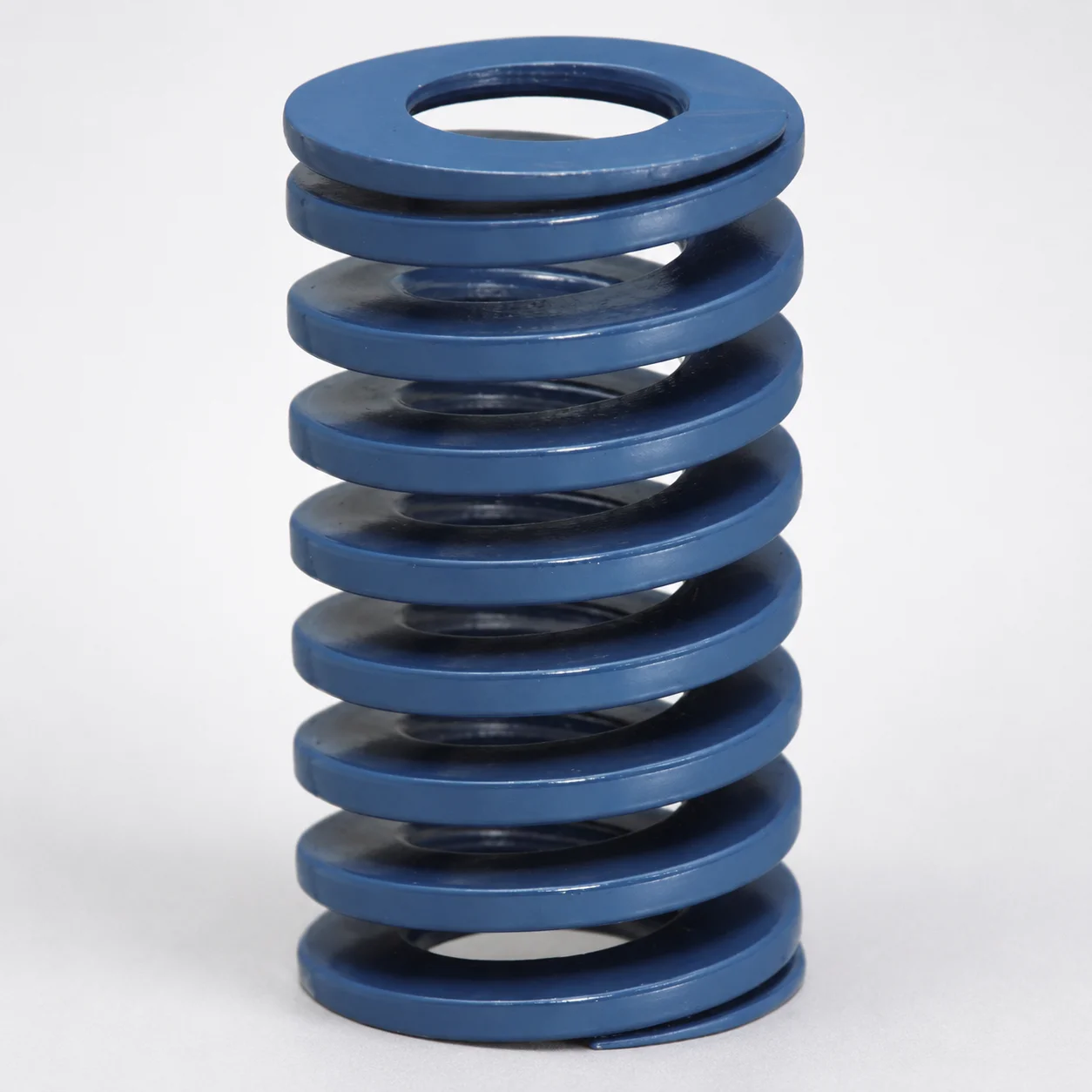
JIS Standard Chrome Silicon Steel Medium Duty Die Spring - 40% Deflection
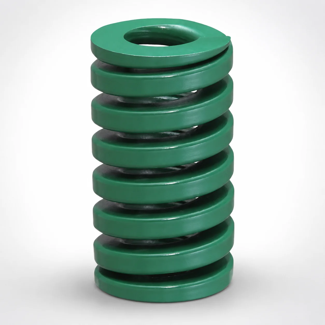
JIS Standard Heavy Duty Die Spring 24% Deflection
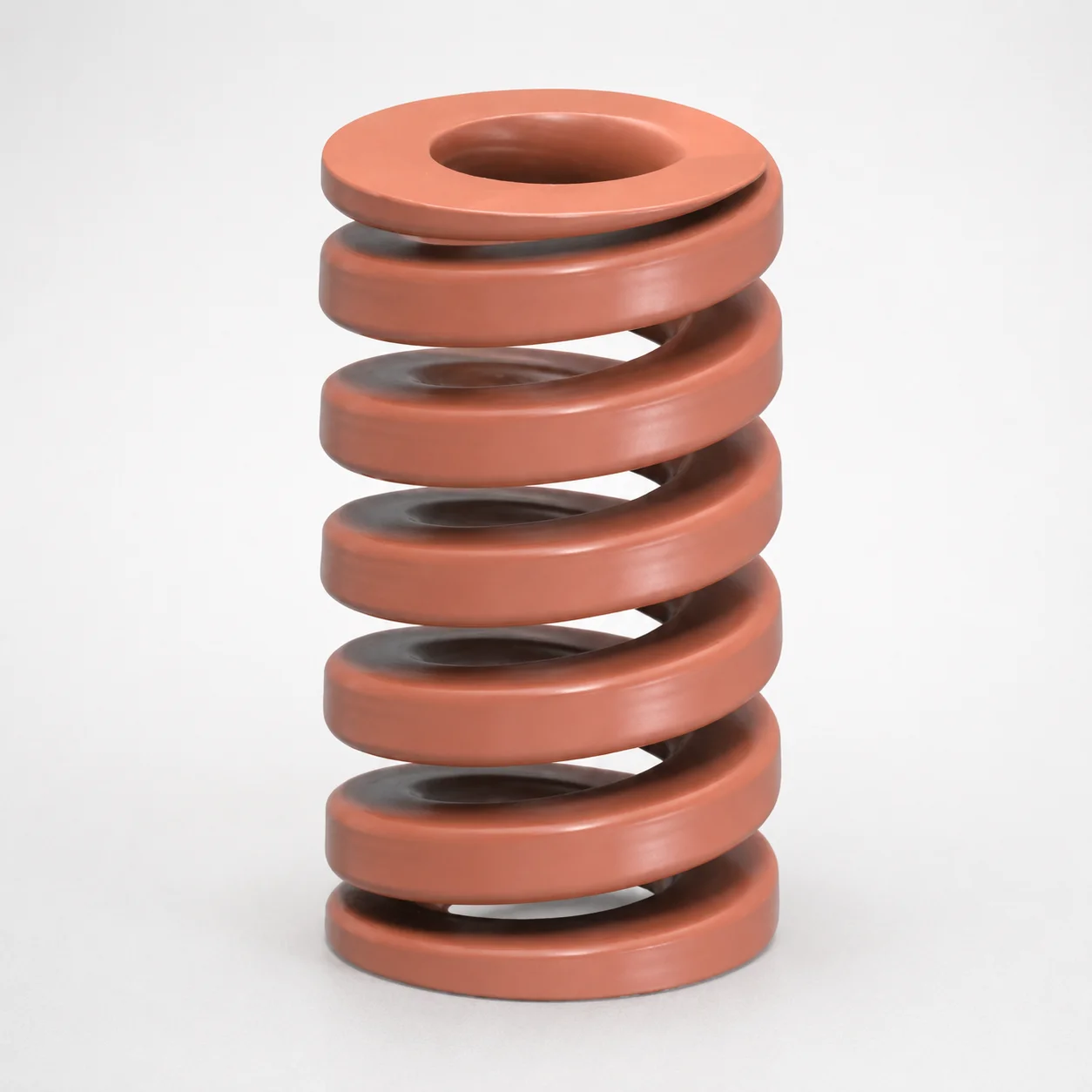
JIS Standard Chrome Silicon Oil-Tempered Wire Heavy Duty Die Spring 20% Deflection
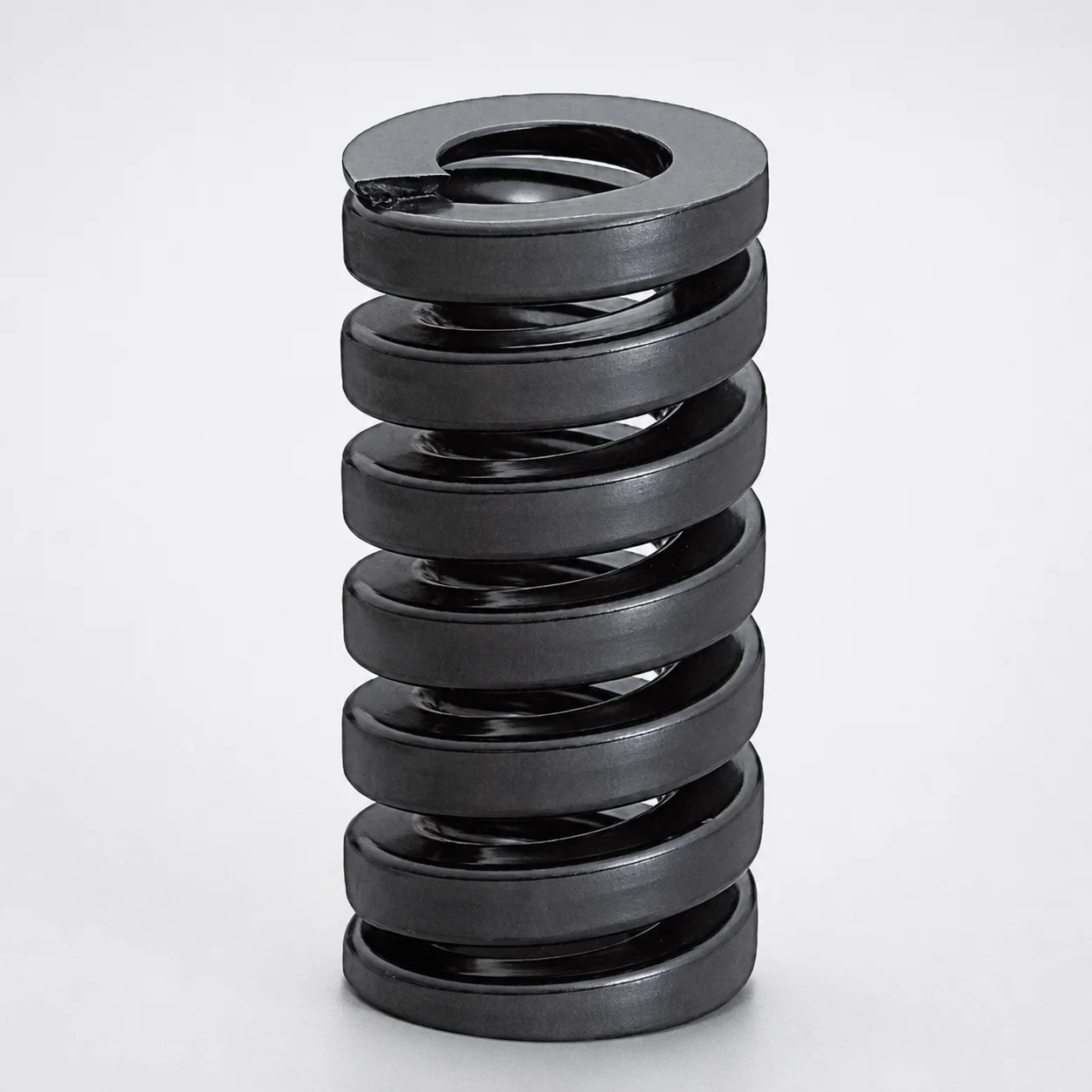
JIS Standard Extra Heavy Duty Die Spring SWG Type - 20% Deflection
Need Custom Specifications?
Our engineering team can help with custom configurations, material selection, and volume pricing.