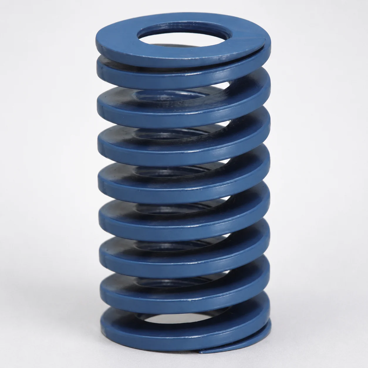
JIS Standard Chrome Silicon Steel Medium Duty Die Spring - 40% Deflection
Medium Duty Die Spring - 40% Deflection (Chrome silicon steel, SWOSC-V equivalent) is an oil-tempered coil spring built to maintain consistent force behavior across typical die loading conditions.
- 40% deflection rating balances strength and flexibility for medium-duty die applications
- Chrome silicon steel construction from SWOSC-V equivalent oil-tempered wire supports reliable performance
- Accepts a wide range of maximum load depending on selected size for load matching
- JIS compliance helps integration with standard tooling and spring system specifications
Specifications
538 configurations available
| Maximum Load (N) | Outer Diameter D (mm) | Length L (mm) | Coating Removal | type |
|---|---|---|---|---|
| 78 | 6 | 15 | No coating | - |
| 78 | 6 | 20 | No coating | - |
| 78 | 6 | 25 | No coating | - |
| 78 | 6 | 30 | No coating | - |
| 78 | 6 | 35 | No coating | - |
| 78 | 6 | 40 | No coating | - |
| 98 | 8 | 10 | No coating | - |
| 98 | 8 | 15 | No coating | - |
| 98 | 8 | 20 | No coating | - |
| 98 | 8 | 25 | No coating | - |
| 98 | 8 | 30 | No coating | - |
| 98 | 8 | 35 | No coating | - |
| 98 | 8 | 40 | No coating | - |
| 98 | 8 | 45 | No coating | - |
| 98 | 8 | 50 | No coating | - |
| 98 | 8 | 55 | No coating | - |
| 98 | 8 | 60 | No coating | - |
| 98 | 8 | 65 | No coating | - |
| 98 | 8 | 70 | No coating | - |
| 98 | 8 | 75 | No coating | - |
| 98 | 8 | 80 | No coating | - |
| 137 | 10 | 10 | No coating | - |
| 137 | 10 | 15 | No coating | - |
| 137 | 10 | 20 | No coating | - |
| 137 | 10 | 25 | No coating | - |
| 137 | 10 | 30 | No coating | - |
| 137 | 10 | 35 | No coating | - |
| 137 | 10 | 40 | No coating | - |
| 137 | 10 | 45 | No coating | - |
| 137 | 10 | 50 | No coating | - |
| 137 | 10 | 55 | No coating | - |
| 137 | 10 | 60 | No coating | - |
| 137 | 10 | 65 | No coating | - |
| 137 | 10 | 70 | No coating | - |
| 137 | 10 | 75 | No coating | - |
| 137 | 10 | 80 | No coating | - |
| 137 | 10 | 90 | No coating | - |
| 206 | 12 | 15 | No coating | - |
| 206 | 12 | 20 | No coating | - |
| 206 | 12 | 25 | No coating | - |
| 206 | 12 | 30 | No coating | - |
| 206 | 12 | 35 | No coating | - |
| 206 | 12 | 40 | No coating | - |
| 206 | 12 | 45 | No coating | - |
| 206 | 12 | 50 | No coating | - |
| 206 | 12 | 55 | No coating | - |
| 206 | 12 | 60 | No coating | - |
| 206 | 12 | 65 | No coating | - |
| 206 | 12 | 70 | No coating | - |
| 206 | 12 | 75 | No coating | - |
Product Guide
Application Scenarios+
This medium-duty die spring is used inside die sets to compensate for part thickness variation and to maintain stable return force in repeat press cycles.
- Automotive stamping and connector housings: Select the spring to deliver reliable force at the specified 40% deflection level, helping the punch and die maintain consistent contact and ejection behavior under medium loading (maximum load range up to 5978 N).
- Industrial progressive dies: The chrome silicon steel oil-tempered construction supports stable spring force across typical die loading conditions, reducing force drift that can affect indexing and forming quality.
- Fixture and gauging dies: For setups requiring predictable load response without over-stiff behavior, the balanced 40% deflection rating provides flexibility while still offering meaningful load capacity.
Because this variant is built for JIS-standard integration and uses chrome silicon steel (SWOSC-V equivalent) oil-tempered wire, it is well suited for die spring systems that need consistent performance and straightforward specification matching.
Material & Process Details+
The spring is manufactured from chrome silicon steel with an SWOSC-V equivalent wire. This steel family is selected for good hardenability and strong fatigue resistance in repeatedly loaded die spring applications.
- Manufacturing condition: Oil-tempered (oil-tempered wire spring construction) to stabilize spring behavior after forming.
- Hardness & performance balance: The tempered spring condition provides a practical trade-off of wear resistance and toughness, supporting long service life under compressive cycling while avoiding excessive brittleness.
- Coating compatibility: The spring can be supplied with no coating or coated options to match corrosion environment requirements.
Compared with higher-chromium wear steels used for tooling inserts, this spring steel prioritizes fatigue life and controlled force rather than cutting or abrasion capability.
Sizing & Selection Guide+
To select the correct die spring, match your die set’s required return behavior at the target deflection to the spring’s 40% deflection design condition, then verify geometry compatibility.
- Choose by load requirement: Confirm that the needed Maximum Load (N) falls within the available range of 78 ~ 5978 N.
- Verify outer diameter: Select an Outer Diameter D between 6 ~ 70 mm so the spring fits the guide space in the die set and maintains proper alignment.
- Set free/installed length compatibility: Use the available Length L range of 10 ~ 500 mm to ensure sufficient working travel and clearance through the press stroke.
- Coating selection: Pick no coating or coated based on the corrosion exposure of your die cavity area.
Where fit depends on surrounding guides, allow for assembly clearance around D and confirm installation height so the spring operates near the intended deflection without coil bind.
Frequently Asked Questions
How do I choose a die spring size to achieve the required force at 40% deflection?+
What material grade is the chrome silicon steel equivalent and why is it used for die spring duty?+
Are there different surface options for corrosion resistance?+
How do I prevent misfit when selecting outer diameter and length for a die set?+
How can I ensure the spring’s maximum load rating matches medium-duty stamping requirements?+
Related Products
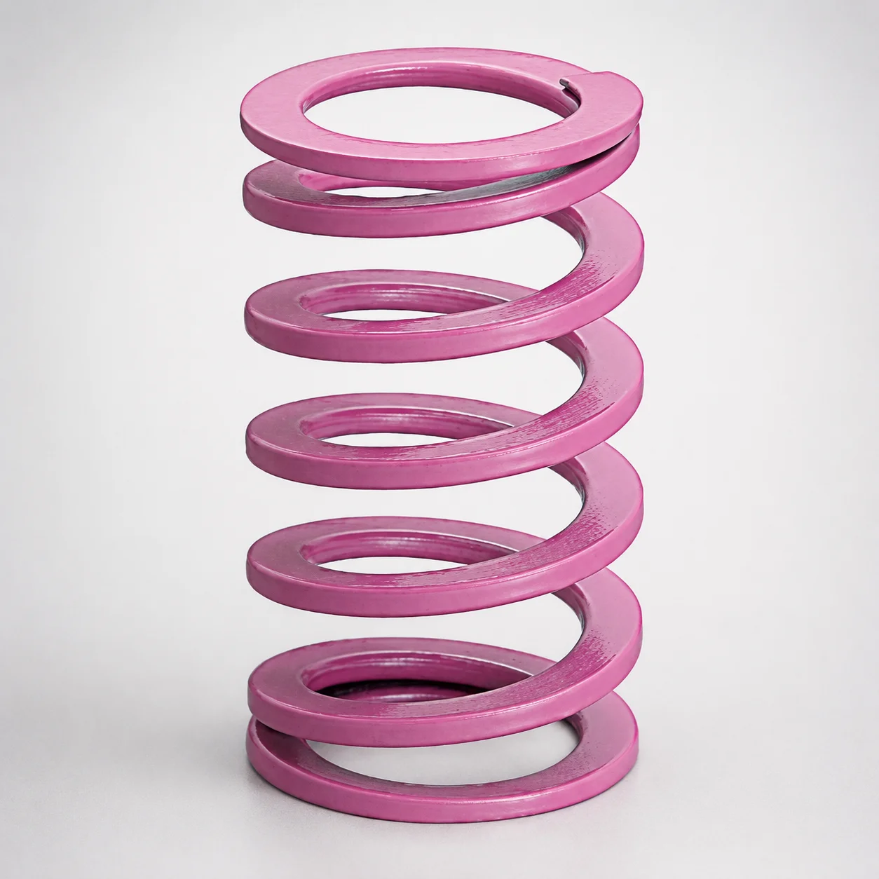
JIS Standard Chrome Silicon Medium Duty Die Spring 60% Deflection
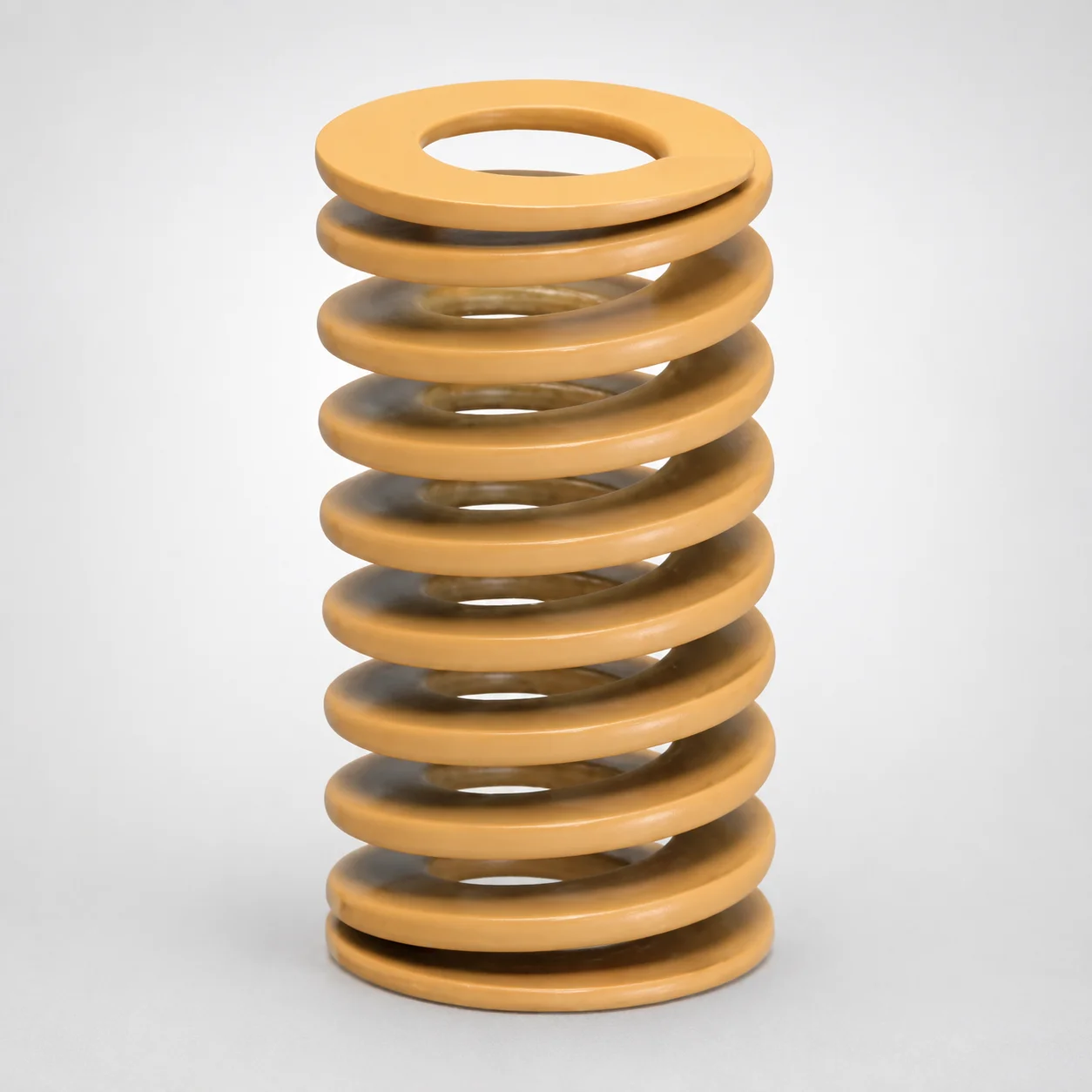
JIS Standard Chrome Silicon Medium Duty Die Spring - 50% Deflection
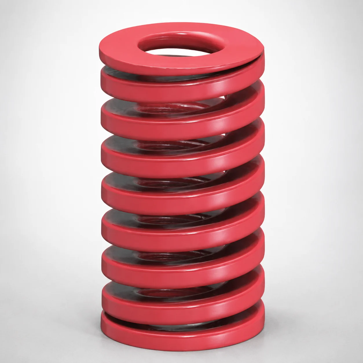
JIS Standard Medium Duty Die Spring 32% Deflection Chrome Silicon Coil Springs
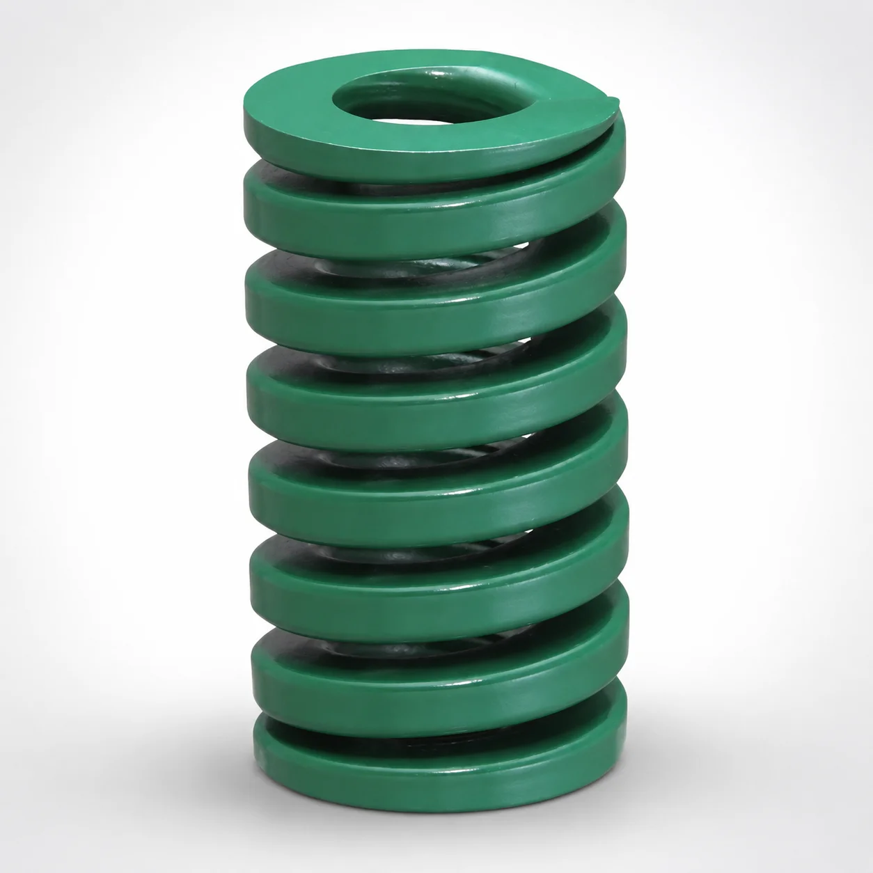
JIS Standard Heavy Duty Die Spring 24% Deflection
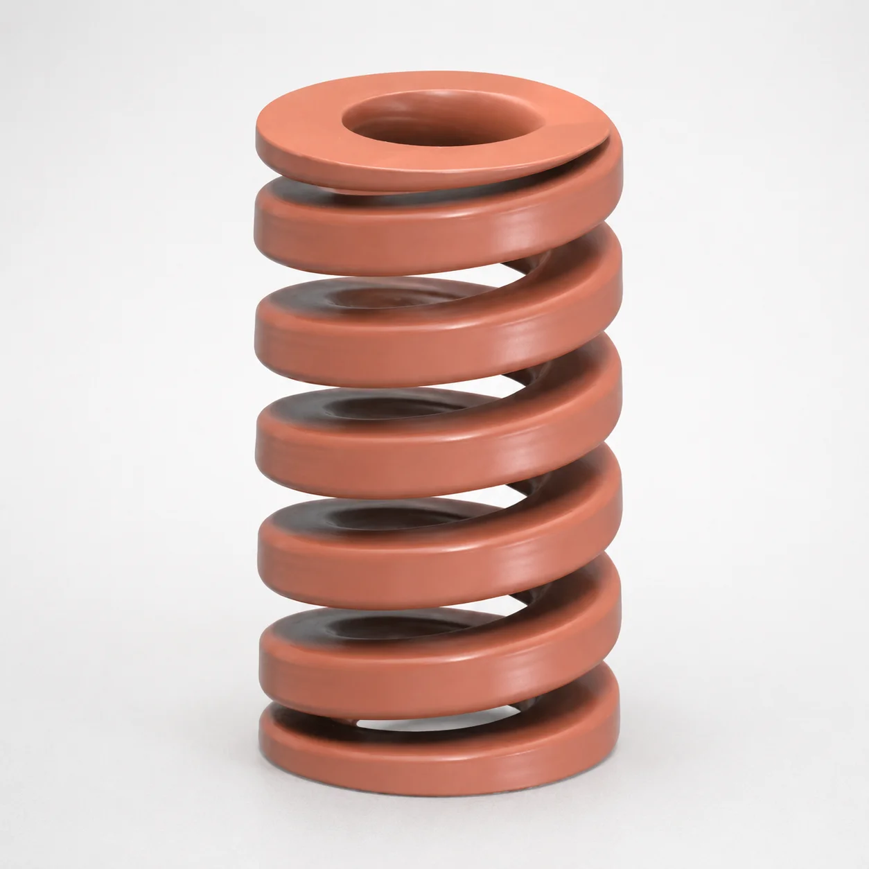
JIS Standard Chrome Silicon Oil-Tempered Wire Heavy Duty Die Spring 20% Deflection
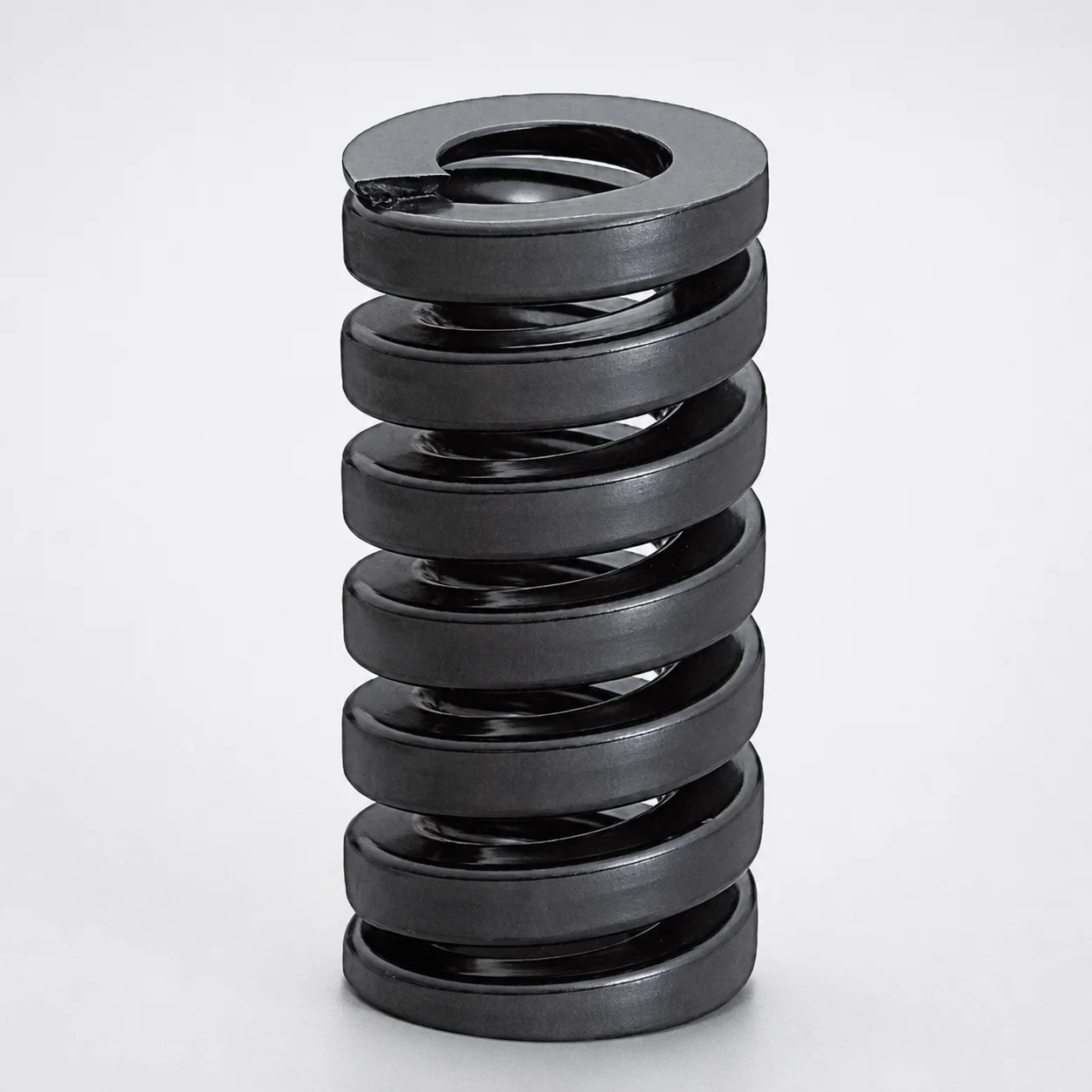
JIS Standard Extra Heavy Duty Die Spring SWG Type - 20% Deflection
Need Custom Specifications?
Our engineering team can help with custom configurations, material selection, and volume pricing.