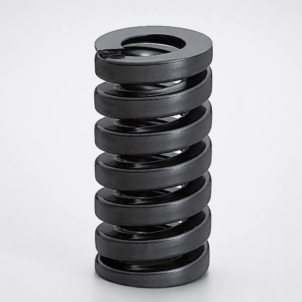
JIS Standard Extra Heavy Duty Die Spring SWG Type - 20% Deflection
Extra Heavy Duty Die Spring (SWG type) is engineered for heavy die setups with a 20% deflection ratio, providing resilient support and stable force under demanding mechanical loading.
- Designed for extra-heavy loads with consistent spring response at 20% deflection
- Chrome-silicon construction helps maintain strength and fatigue resistance in die service
- Manufactured to JIS standard for reliable fit and predictable performance in tooling assemblies
- Ideal for industrial stamping and forming dies requiring shock absorption and structural integrity
Specifications
207 configurations available
| Allowable Deflection Ratio (%) | Maximum Load (N) | Outer Diameter D (mm) | Length L (mm) | type |
|---|---|---|---|---|
| 18 | 441 | 10 | 15 | - |
| 20 | 490 | 10 | 20 | - |
| 20 | 490 | 10 | 25 | - |
| 20 | 490 | 10 | 30 | - |
| 20 | 490 | 10 | 35 | - |
| 20 | 490 | 10 | 40 | - |
| 20 | 490 | 10 | 45 | - |
| 20 | 490 | 10 | 50 | - |
| 20 | 490 | 10 | 55 | - |
| 20 | 490 | 10 | 60 | - |
| 20 | 490 | 10 | 65 | - |
| 20 | 490 | 10 | 70 | - |
| 20 | 490 | 10 | 75 | - |
| 20 | 490 | 10 | 80 | - |
| 20 | 490 | 10 | 90 | - |
| 20 | 490 | 10 | 100 | - |
| 18 | 662 | 12 | 15 | - |
| 20 | 735 | 12 | 20 | - |
| 20 | 735 | 12 | 25 | - |
| 20 | 735 | 12 | 30 | - |
| 20 | 735 | 12 | 35 | - |
| 20 | 735 | 12 | 40 | - |
| 20 | 735 | 12 | 45 | - |
| 20 | 735 | 12 | 50 | - |
| 20 | 735 | 12 | 55 | - |
| 20 | 735 | 12 | 60 | - |
| 20 | 735 | 12 | 65 | - |
| 20 | 735 | 12 | 70 | - |
| 20 | 735 | 12 | 75 | - |
| 20 | 735 | 12 | 80 | - |
| 20 | 735 | 12 | 90 | - |
| 20 | 735 | 12 | 100 | - |
| 18 | 856 | 14 | 20 | - |
| 20 | 951 | 14 | 25 | - |
| 20 | 951 | 14 | 30 | - |
| 20 | 951 | 14 | 35 | - |
| 20 | 951 | 14 | 40 | - |
| 20 | 951 | 14 | 45 | - |
| 20 | 951 | 14 | 50 | - |
| 20 | 951 | 14 | 55 | - |
| 20 | 951 | 14 | 60 | - |
| 20 | 951 | 14 | 65 | - |
| 20 | 951 | 14 | 70 | - |
| 20 | 951 | 14 | 75 | - |
| 20 | 951 | 14 | 80 | - |
| 20 | 951 | 14 | 90 | - |
| 20 | 951 | 14 | 100 | - |
| 18 | 1147 | 16 | 20 | - |
| 20 | 1275 | 16 | 25 | - |
| 20 | 1275 | 16 | 30 | - |
Product Guide
Application Scenarios+
This extra heavy duty die spring is used inside injection mold tooling and similar press-based systems where the die must withstand repeated mechanical shock while maintaining stable clamp and return behavior. The 18–20% deflection rating supports predictable force response when components experience cyclical opening/closing or localized overloads.
Common scenarios include automotive stamping and forming die sets, where the spring helps absorb impact and recover die position after high-load strikes. It is also suited for industrial transfer or forming stations that rely on consistent return forces for guides, cams, or stripper-related mechanisms.
For molds that see heavy die service, this variant’s engineered load support at 20% deflection helps reduce instability under peak loads and improves fatigue reliability compared with lighter die springs.
- Use in die assemblies requiring stable force during repeated high mechanical loading
- Pair with tooling structures designed around the specified deflection ratio for consistent actuator behavior
Material & Process Details+
The SWG type die spring is described as chrome-silicon construction, a common spring steel family chosen for high strength and good fatigue resistance under cyclic loading. Chrome-silicon steels are typically heat treated to balance wear/abrasion resistance and spring toughness, helping maintain load characteristics over long service cycles.
For die-spring applications, the hardness is controlled by the spring heat treatment state (typically quenched and tempered, or equivalent spring-optimized treatment), targeting an appropriate compromise between elastic recovery and durability. In general, higher hardness improves resistance to permanent deformation, while lower toughness can increase risk of cracking under shock.
- Material focus: chrome-silicon spring properties for fatigue resistance in die service
- Heat treatment: spring-optimized quench/temper to set elastic strength
- Trade-off: maintain toughness for impact resistance while achieving sufficient hardness for stable deflection
Note: Specific HRC values are not provided in the input data.
Sizing & Selection Guide+
Select the die spring geometry by matching both deflection ratio and the required load range for your mold/die mechanism. This series supports Allowable Deflection Ratio values of 18% or 20%, so choose the ratio your assembly is designed to operate at—especially if your actuator travel and force curve were calculated for 20% deflection.
Dimension selection is based on Outer Diameter D from 10 to 50 mm and length L from 15 to 200 mm. Once you know the available space and the working stroke envelope, choose D to fit the surrounding guide/seat constraints and choose L to ensure the spring can compress to the intended deflection without bottoming out.
- Match deflection ratio (18% vs 20%) to your force/behavior assumptions
- Choose D (10–50 mm) to fit the die cavity/core surrounding clearances
- Choose L (15–200 mm) to maintain stroke margin at the target deflection
Tolerance note: The input data does not provide tolerance values; confirm spring dimensional tolerances from the JIS/series documentation used by your supplier/manufacturer.
Frequently Asked Questions
How do I choose between 18% and 20% allowable deflection for die springs in mold assemblies?+
What load range can this SWG extra heavy duty die spring support for sizing a heavy die return or compensation function?+
How do I select outer diameter D and length L to prevent coil bind in a die spring seat?+
Is chrome-silicon construction appropriate for fatigue-prone heavy die service?+
Does this product meet a specific standard, and how does that affect interchangeability?+
Related Products
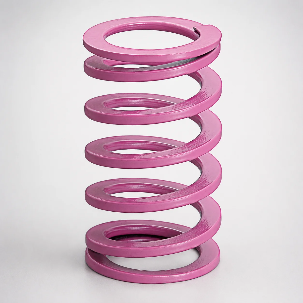
JIS Standard Chrome Silicon Medium Duty Die Spring 60% Deflection
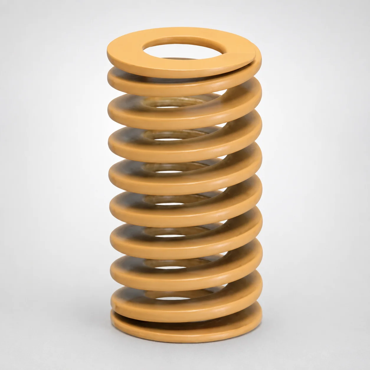
JIS Standard Chrome Silicon Medium Duty Die Spring - 50% Deflection
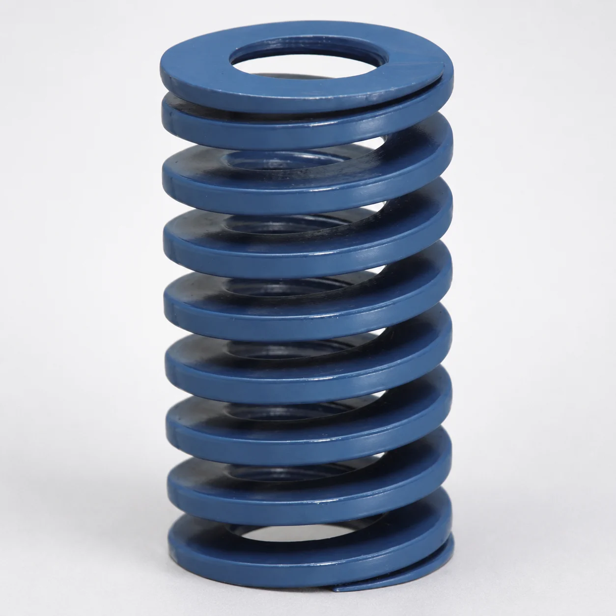
JIS Standard Chrome Silicon Steel Medium Duty Die Spring - 40% Deflection
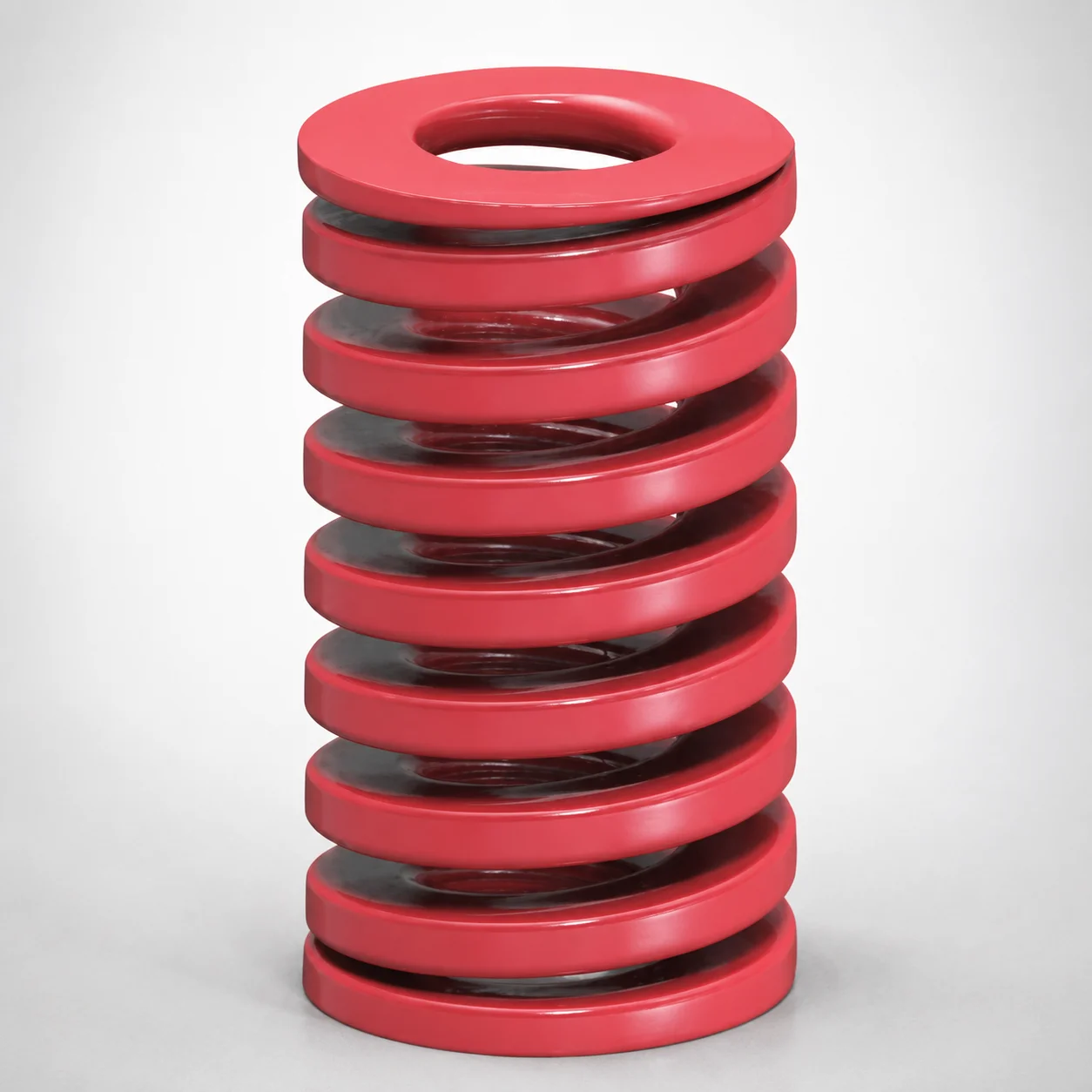
JIS Standard Medium Duty Die Spring 32% Deflection Chrome Silicon Coil Springs
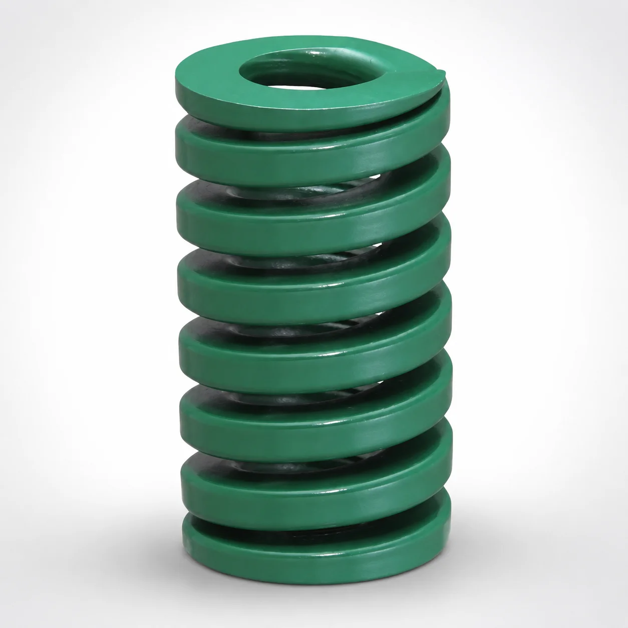
JIS Standard Heavy Duty Die Spring 24% Deflection
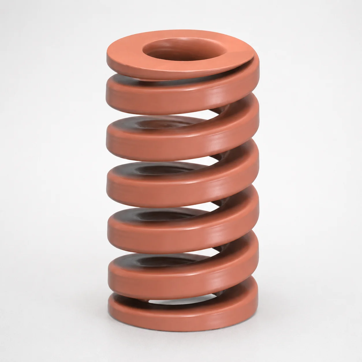
JIS Standard Chrome Silicon Oil-Tempered Wire Heavy Duty Die Spring 20% Deflection
Need Custom Specifications?
Our engineering team can help with custom configurations, material selection, and volume pricing.