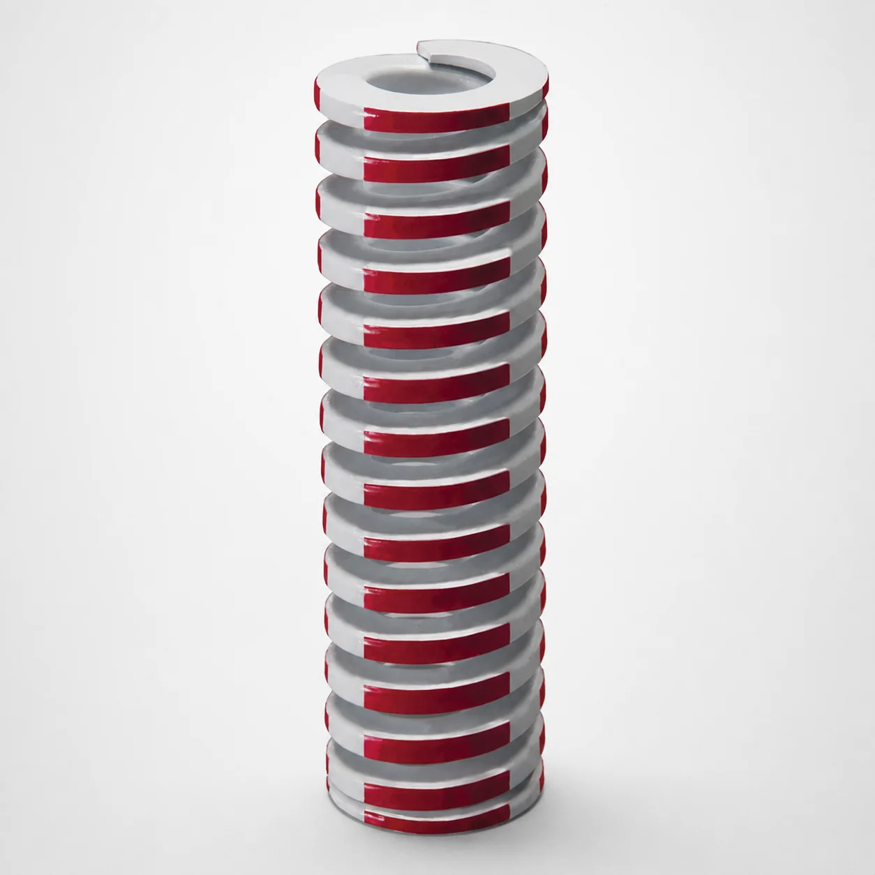
Inch Medium Heavy Duty Die Spring 35% Deflection Chrome Silicon
Medium Heavy Duty die spring (Chrome silicon steel) with 35% allowable deflection is designed to provide dependable die cushioning in production tooling. Built for stable load response and consistent press operation.
- Medium heavy duty spring rate supports controlled cushioning under die load
- Made from chrome silicon steel for strong resilience
- Optimized for 35% deflection to match medium load requirements
- Inch format design suitable for standard die spring assemblies
Specifications
97 configurations available
| Outer Diameter D (in) | Length L (in) | Max. comp. length (in) | Rod Diameter (in) |
|---|---|---|---|
| 3/4" | 1-1/4" | 0.72" | 3/8" |
| 3/4" | 1" | 0.58" | 3/8" |
| 3/4" | 1-3/4" | 1.02" | 3/8" |
| 3/4" | 1-1/2" | 0.87" | 3/8" |
| 3/4" | 2" | 1.16" | 3/8" |
| 3/4" | 2-1/2" | 1.46" | 3/8" |
| 3/4" | 3" | 1.74" | 3/8" |
| 3/4" | 3-1/2" | 2.02" | 3/8" |
| 3/4" | 4" | 2.31" | 3/8" |
| 3/4" | 4-1/2" | 2.62" | 3/8" |
| 3/4" | 5" | 2.86" | 3/8" |
| 3/4" | 5-1/2" | 3.15" | 3/8" |
| 3/4" | 12" | 6.78" | 3/8" |
| 3/4" | 6" | 3.45" | 3/8" |
| 1" | 1-1/4" | 0.75" | 1/2" |
| 1" | 1" | 0.61" | 1/2" |
| 1" | 1-3/4" | 1.02" | 1/2" |
| 1" | 1-1/2" | 0.89" | 1/2" |
| 1" | 2" | 1.15" | 1/2" |
| 1" | 2-1/2" | 1.44" | 1/2" |
| 1" | 3" | 1.73" | 1/2" |
| 1" | 3-1/2" | 2.02" | 1/2" |
| 1" | 4" | 2.30" | 1/2" |
| 1" | 4-1/2" | 2.59" | 1/2" |
| 1" | 5" | 2.88" | 1/2" |
| 1" | 5-1/2" | 3.16" | 1/2" |
| 1" | 6" | 3.45" | 1/2" |
| 1" | 7" | 4.03" | 1/2" |
| 1" | 12" | 6.70" | 1/2" |
| 1" | 8" | 4.60" | 1/2" |
| 1-1/4" | 1-3/4" | 1.07" | 5/8" |
| 1-1/4" | 1-1/2" | 0.92" | 5/8" |
| 1-1/4" | 2" | 1.22" | 5/8" |
| 1-1/4" | 2-1/2" | 1.55" | 5/8" |
| 1-1/4" | 3" | 1.83" | 5/8" |
| 1-1/4" | 3-1/2" | 2.12" | 5/8" |
| 1-1/4" | 4" | 2.43" | 5/8" |
| 1-1/4" | 4-1/2" | 2.68" | 5/8" |
| 1-1/4" | 5" | 2.94" | 5/8" |
| 1-1/4" | 5-1/2" | 3.22" | 5/8" |
| 1-1/4" | 6" | 3.58" | 5/8" |
| 1-1/4" | 7" | 4.10" | 5/8" |
| 1-1/4" | 8" | 4.76" | 5/8" |
| 1-1/4" | 12" | 6.94" | 5/8" |
| 1-1/4" | 10" | 5.78" | 5/8" |
| 1-1/2" | 2" | 1.21" | 3/4" |
| 1-1/2" | 2-1/2" | 1.51" | 3/4" |
| 1-1/2" | 3" | 1.75" | 3/4" |
| 1-1/2" | 3-1/2" | 2.08" | 3/4" |
| 1-1/2" | 4" | 2.31" | 3/4" |
Product Guide
Application Scenarios+
Die springs in inch-format injection and stamping tooling are used to cushion the press and maintain stable shut height under repeated cycles. This 35% allowable-deflection spring is well suited for medium-load die cushioning, where consistent load response is critical for part repeatability.
- Automotive component tooling: Helps absorb small variations in die closure force during forming or insert placement, reducing shock loads and promoting uniform operation.
- Industrial housing and bracket dies: The medium heavy duty spring rate supports controlled cushioning, helping maintain reliable press conditions over long production runs.
- High-mix production dies with frequent changeovers: The optimized 35% deflection allowance supports predictable spring behavior within its design stroke range.
Chrome silicon steel is chosen for resilience, making this variant a practical option where durability and stable cushioning are required in inch die spring assemblies.
Material & Process Details+
This die spring uses chrome silicon steel, a spring alloy commonly selected for its strong elastic recovery and good fatigue resistance in cyclic press applications. The key performance goal is reliable load response while resisting permanent set under repeated compression.
- Hardness / wear resistance: While exact HRC is not provided in the supplied specification, chrome silicon die spring steels are typically specified for a hardness state that supports high fatigue life and adequate surface wear resistance.
- Toughness trade-off: Increasing hardness improves resistance to deformation, but can reduce toughness; the intended “medium heavy duty” behavior is balanced to maintain cushioning stability within the 35% allowable deflection.
- Heat treatment: Spring alloys like this are generally quenched and tempered to achieve the required spring temper and dimensional stability.
If you are comparing alternatives, steels optimized for maximum hardness may offer higher wear resistance but can be more sensitive to shock; chrome silicon is commonly selected for its overall fatigue-resilience balance.
Sizing & Selection Guide+
Select the die spring dimensions to match the available space in your inch die spring assembly while staying within the spring’s designed deflection capability.
- Outer diameter (D): Choose from 1 ~ 5 in to fit the surrounding guide/seat clearance and prevent interference during compression.
- Length (L): Select 1 ~ 12 in based on installed height and the available free length in the mold/die stack.
- Max. compressed length: Verify the 0.5 ~ 6.94 in max. comp. length against your required closed-die position to ensure you do not exceed allowable stroke.
- Rod diameter: For assemblies using a rod/guide, confirm 1 ~ 11 in rod diameter compatibility with your guide hardware.
Because tolerances are not specified here, finalize by checking fit-up drawings for seat/guides and confirming that your planned deflection remains within the 35% allowable deflection design intent for predictable cushioning.
Frequently Asked Questions
How do I size this die spring to ensure the press stroke stays within the 35% allowable deflection?+
Which dimension controls interference risk in an inch-format die spring pocket—outer diameter D or free length L?+
What is the practical compatibility consideration for assemblies using a guide rod (rod diameter range 1 ~ 11 in)?+
What material properties should I expect from chrome silicon steel for die cushioning?+
When choosing between medium heavy duty die springs, how should I interpret the max. compressed length spec?+
Related Products
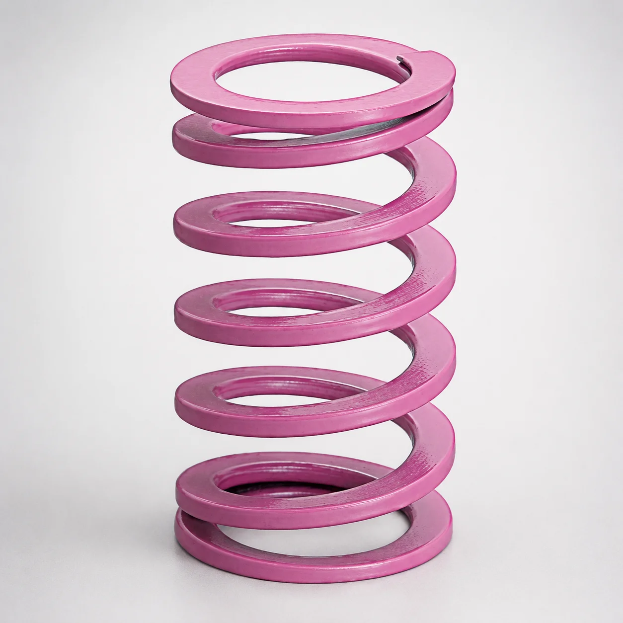
JIS Standard Chrome Silicon Medium Duty Die Spring 60% Deflection
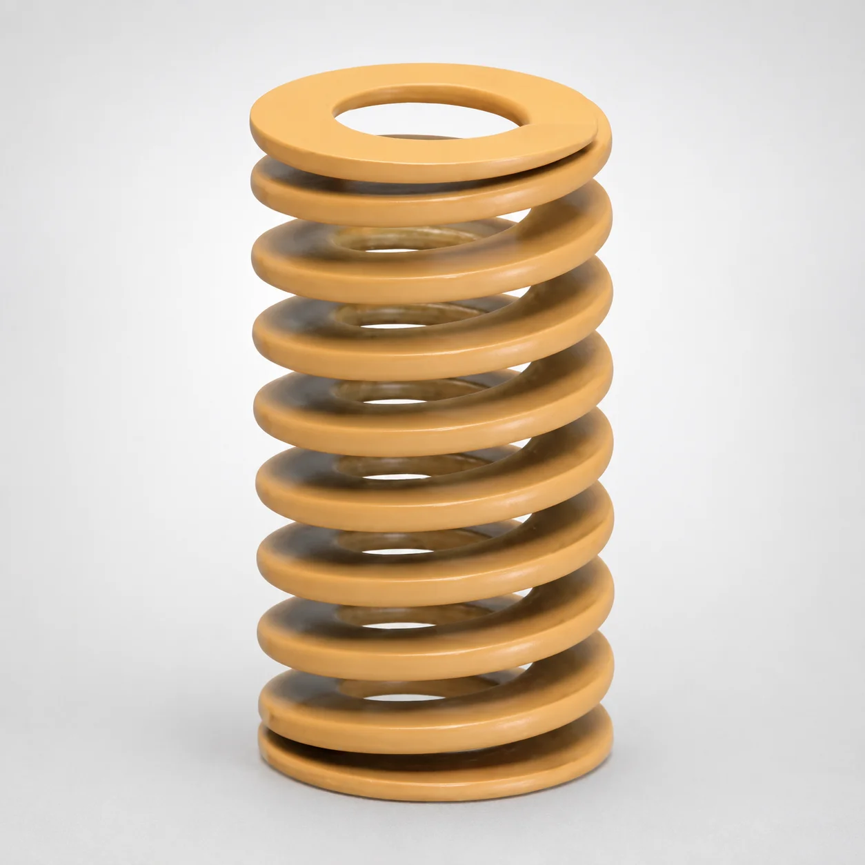
JIS Standard Chrome Silicon Medium Duty Die Spring - 50% Deflection
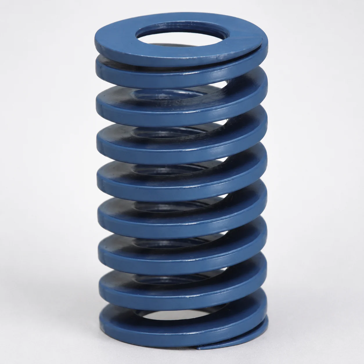
JIS Standard Chrome Silicon Steel Medium Duty Die Spring - 40% Deflection
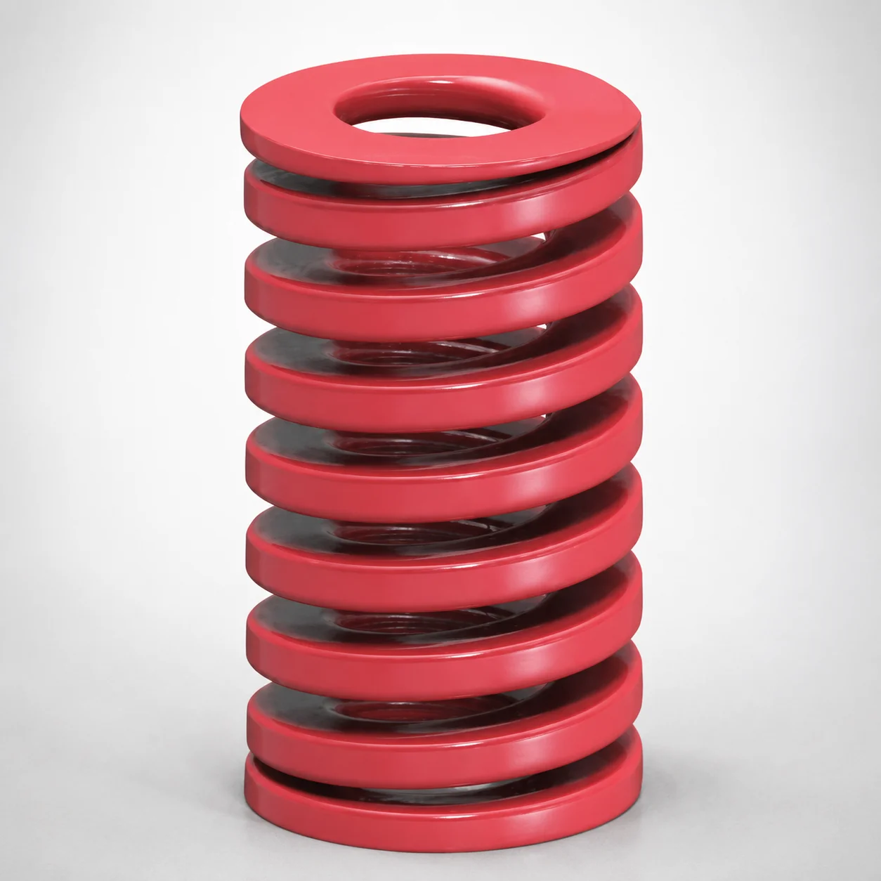
JIS Standard Medium Duty Die Spring 32% Deflection Chrome Silicon Coil Springs
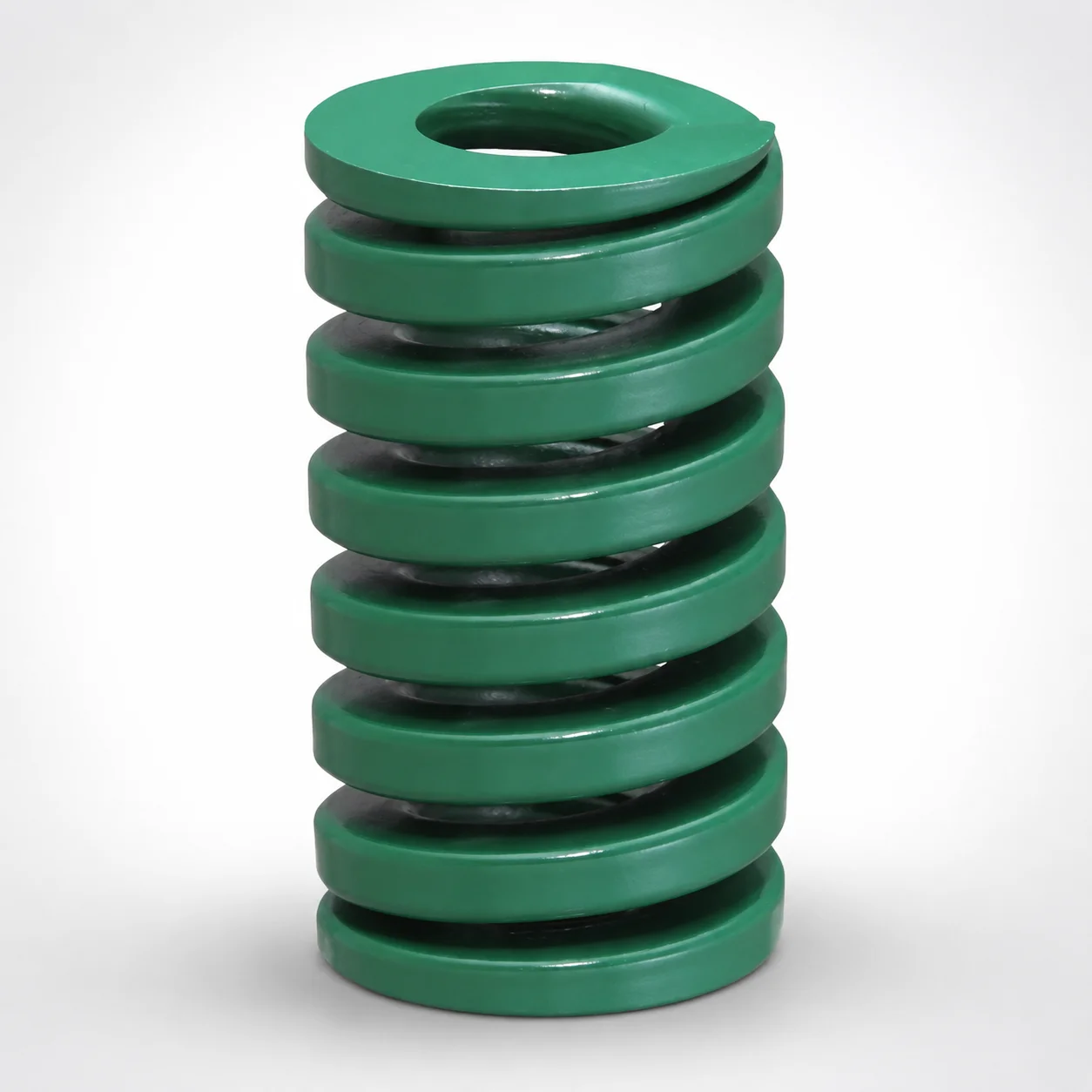
JIS Standard Heavy Duty Die Spring 24% Deflection
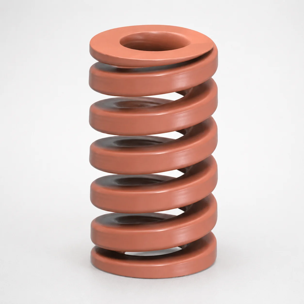
JIS Standard Chrome Silicon Oil-Tempered Wire Heavy Duty Die Spring 20% Deflection
Need Custom Specifications?
Our engineering team can help with custom configurations, material selection, and volume pricing.