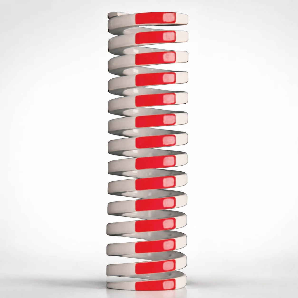
Medium Heavy Duty Die Spring 35% Deflection Chrome Silicon Inch
Medium Heavy Duty Die Spring 35% Deflection (chrome silicon alloy) is engineered for stable load carrying and consistent deflection in die applications. The inch format supports straightforward selection for tooling builds.
- Medium heavy-duty design tuned to 35% allowable deflection under working loads
- High-strength chromium silicon alloy helps maintain spring properties during cycles
- Optimized for die shop assembly where controlled springback improves part repeatability
- Available in inch dimensions to match common North American die component standards
Specifications
97 configurations available
| Outer Diameter D (in) | Length L (in) | d (Inner diameter) (in) |
|---|---|---|
| 3/8" | 1" | 3/16" |
| 3/8" | 1-1/4" | 3/16" |
| 3/8" | 1-1/2" | 3/16" |
| 3/8" | 1-3/4" | 3/16" |
| 3/8" | 2" | 3/16" |
| 3/8" | 2-1/2" | 3/16" |
| 3/8" | 3" | 3/16" |
| 3/8" | 12" | 3/16" |
| 1/2" | 1" | 9/32" |
| 1/2" | 1-1/4" | 9/32" |
| 1/2" | 1-1/2" | 9/32" |
| 1/2" | 1-3/4" | 9/32" |
| 1/2" | 2" | 9/32" |
| 1/2" | 2-1/2" | 9/32" |
| 1/2" | 3" | 9/32" |
| 1/2" | 3-1/2" | 9/32" |
| 1/2" | 12" | 9/32" |
| 5/8" | 1" | 11/32" |
| 5/8" | 1-1/4" | 11/32" |
| 5/8" | 1-1/2" | 11/32" |
| 5/8" | 1-3/4" | 11/32" |
| 5/8" | 2" | 11/32" |
| 5/8" | 2-1/2" | 11/32" |
| 5/8" | 3" | 11/32" |
| 5/8" | 3-1/2" | 11/32" |
| 5/8" | 4" | 11/32" |
| 5/8" | 12" | 11/32" |
| 3/4" | 1" | 3/8" |
| 3/4" | 1-1/4" | 3/8" |
| 3/4" | 1-1/2" | 3/8" |
| 3/4" | 1-3/4" | 3/8" |
| 3/4" | 2" | 3/8" |
| 3/4" | 2-1/2" | 3/8" |
| 3/4" | 3" | 3/8" |
| 3/4" | 3-1/2" | 3/8" |
| 3/4" | 4" | 3/8" |
| 3/4" | 4-1/2" | 3/8" |
| 3/4" | 5" | 3/8" |
| 3/4" | 5-1/2" | 3/8" |
| 3/4" | 6" | 3/8" |
| 3/4" | 12" | 3/8" |
| 1" | 1" | 1/2" |
| 1" | 1-1/4" | 1/2" |
| 1" | 1-1/2" | 1/2" |
| 1" | 1-3/4" | 1/2" |
| 1" | 2" | 1/2" |
| 1" | 2-1/2" | 1/2" |
| 1" | 3" | 1/2" |
| 1" | 3-1/2" | 1/2" |
| 1" | 4" | 1/2" |
Product Guide
Application Scenarios+
Die springs like this are used inside mechanical and hydraulic die sets to maintain controlled springback and stable clamp/load behavior during forming operations. Their consistent 35% allowable deflection makes them suitable for die shoe return systems and precision ejector/stripper actuation where repeatability across cycles matters.
- Automotive and general metal-forming dies: In progressive or transfer die stations, the spring’s chromium-silicon alloy chemistry helps sustain spring performance under repeated load/unload cycles, reducing drift in working height.
- Stamping press tooling: When the die design requires a predictable force-deflection curve, the medium heavy-duty configuration supports reliable load carrying while staying within the specified deflection capability.
- North American die component builds: Inch sizing (OD 1–5 in, length 1–12 in, ID d 1–11 in) allows straightforward selection to match standard die shop component interfaces.
Material & Process Details+
This die spring is made from a chromium-silicon alloy, selected for its ability to retain mechanical properties after service exposure and repeated flexing. Chromium silicon steels are commonly chosen for high springback performance because they offer a strong balance of wear resistance at contact surfaces and toughness needed for cyclic loading.
- Heat treatment (spring practice): Typically supplied in a quenched and tempered spring condition to achieve stable elastic behavior and dimensional reliability.
- Hardness trade-offs: Higher temper resistance supports load retention, while maintaining enough toughness helps prevent brittle failure under shock or misalignment.
- Compared materials: Relative to basic carbon spring steels, chromium-silicon versions generally improve resilience under cycling; compared with fully stainless spring grades, they often prioritize load stability and fatigue performance for die shop environments.
Sizing & Selection Guide+
To select the correct spring for a die tooling assembly, match the spring’s outer diameter (OD D), inner diameter (d), and free length (L) to the available space and the required working deflection. This series covers D = 1–5 in, L = 1–12 in, and d = 1–11 in.
- Check cavity/guide clearance: Use d to ensure clearance over the guide rod or center post, and use D to avoid interference with surrounding die components.
- Set working height and stroke: Choose L so that the spring can operate within the 35% allowable deflection under working loads; undersizing stroke capacity can cause force spike and premature fatigue.
- Tolerance & fit: Because springs are precision components, verify that your design accounts for typical assembly clearances around guides and seats; if your die design uses tight compression seats, confirm the allowable space is consistent with the selected D and L.
Frequently Asked Questions
How do I size this die spring to stay within the specified 35% deflection for a die set?+
Use the selected length L (1–12 in) to ensure the spring’s operating stroke does not exceed the 35% allowable deflection under working loads. In practice, confirm the die’s required working height change corresponds to less than the spring’s allowable deflection; otherwise the load/deflection curve may shift and reduce fatigue life.
Which dimension (D, d, or L) controls clearance around the guide rod in die tooling?+
The inner diameter d (1–11 in) is the controlling dimension for clearance over the center post or guide rod. The outer diameter D (1–5 in) controls the radial clearance to surrounding components, while length L (1–12 in) affects axial fit in the spring pocket.
Is the inch configuration suitable for North American die component interfaces?+
Yes. This series is offered in inch sizes with ranges of D = 1–5 in, d = 1–11 in, and L = 1–12 in, aligning with common North American die spring component standards.
What material advantages does the chromium-silicon alloy provide for cyclic die work?+
The chromium-silicon alloy is selected to maintain reliable springback and load carrying during repeated cycling in die applications. It is engineered for stable elastic behavior, which helps reduce working height drift when the spring undergoes repeated deflection.
How should I choose between different possible OD or ID options for the same die space?+
Use d to guarantee clearance over the guide/center post and use D to avoid contact with nearby die walls or retainers. After confirming clearances, select L to achieve the required free length and keep deflection within the 35% allowable limit for reliable fatigue performance.
Related Products
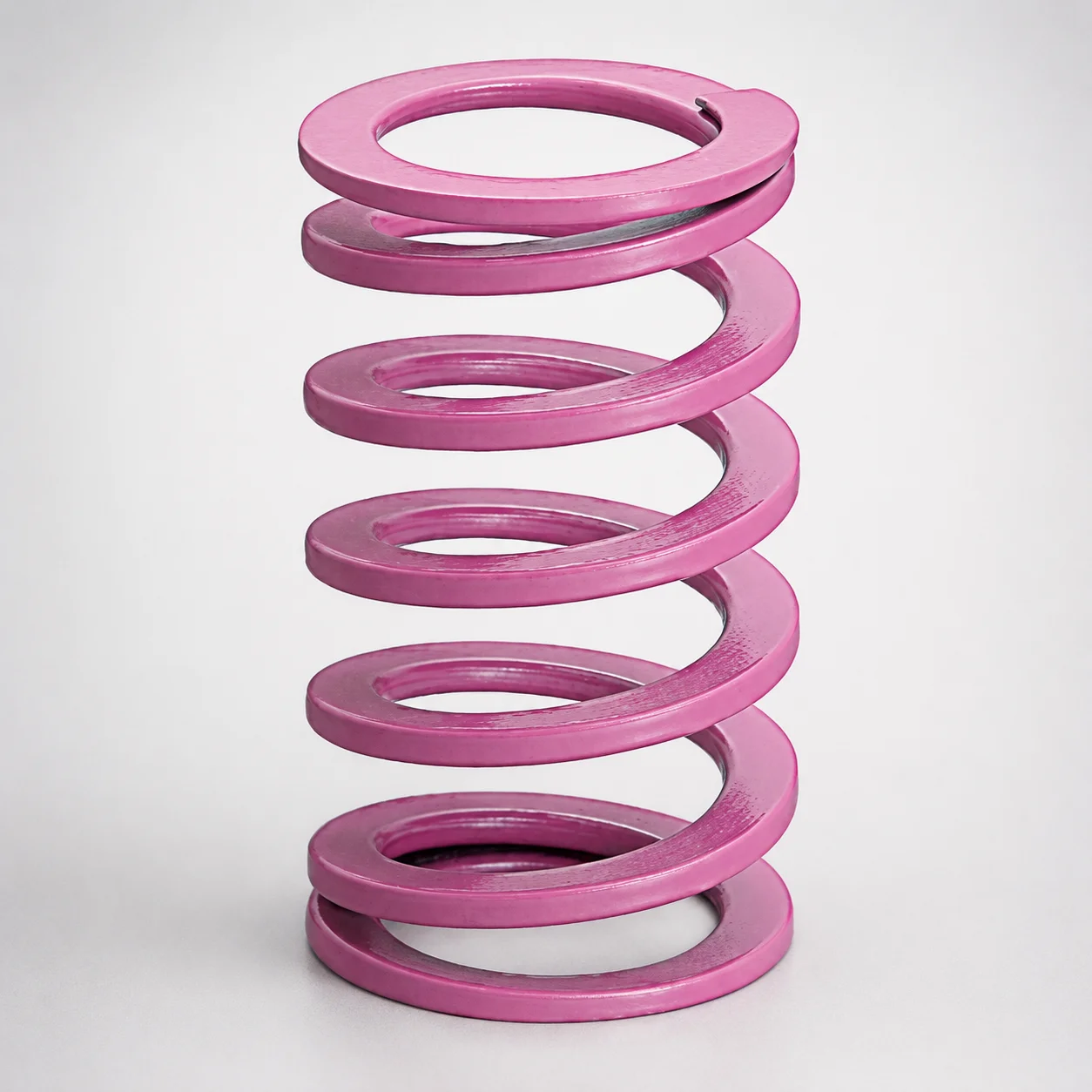
JIS Standard Chrome Silicon Medium Duty Die Spring 60% Deflection
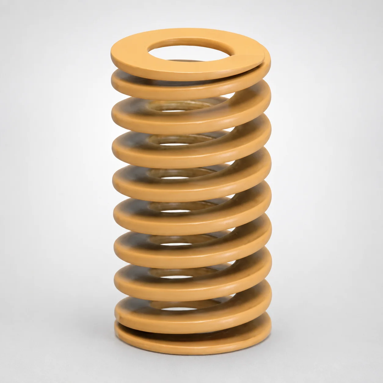
JIS Standard Chrome Silicon Medium Duty Die Spring - 50% Deflection
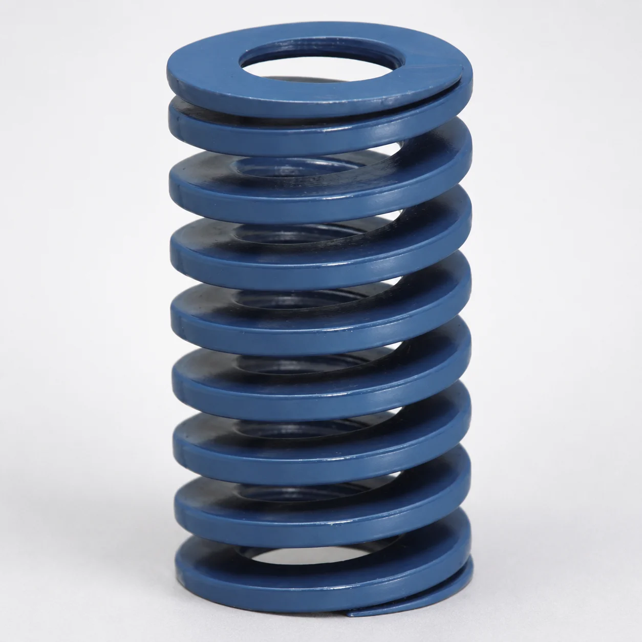
JIS Standard Chrome Silicon Steel Medium Duty Die Spring - 40% Deflection
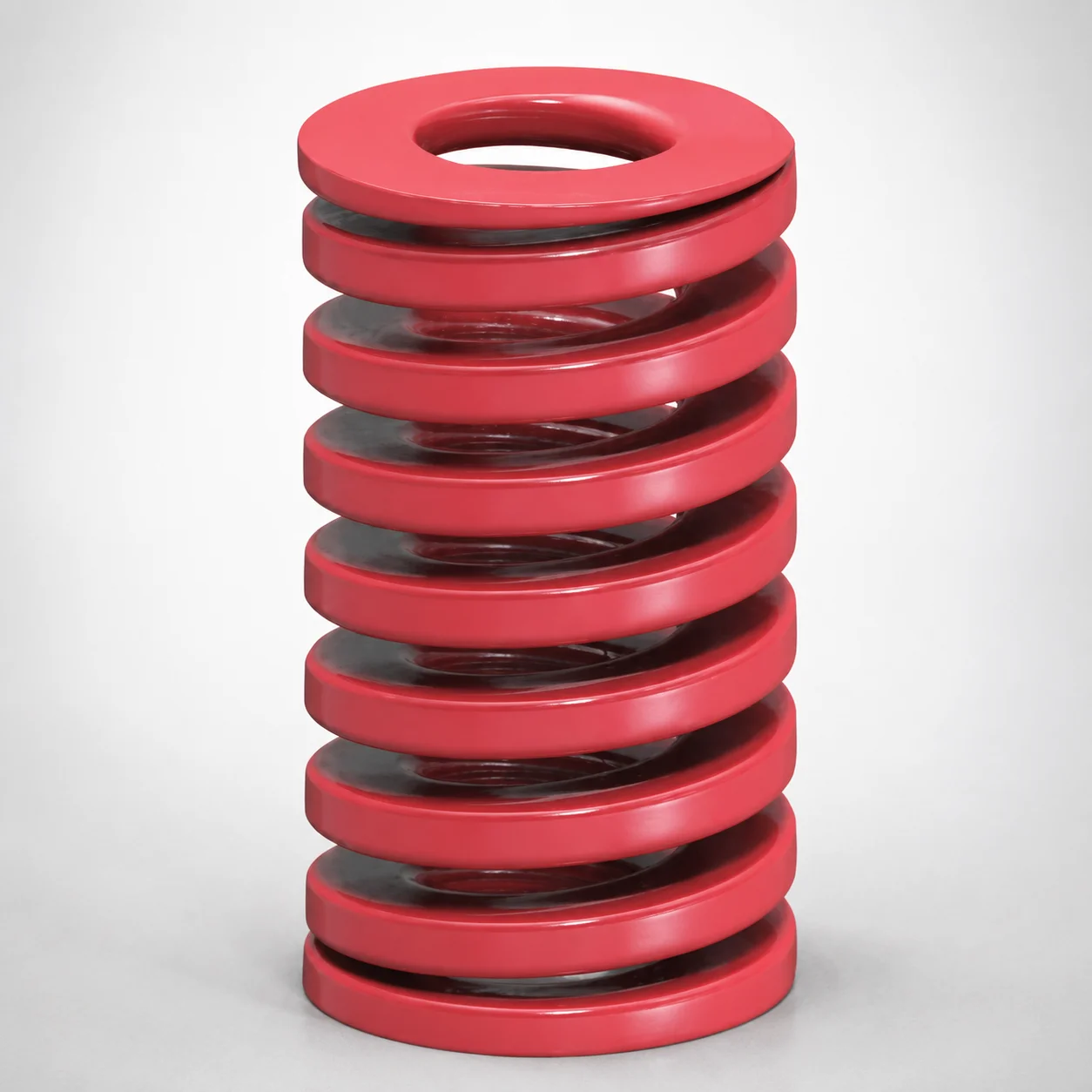
JIS Standard Medium Duty Die Spring 32% Deflection Chrome Silicon Coil Springs
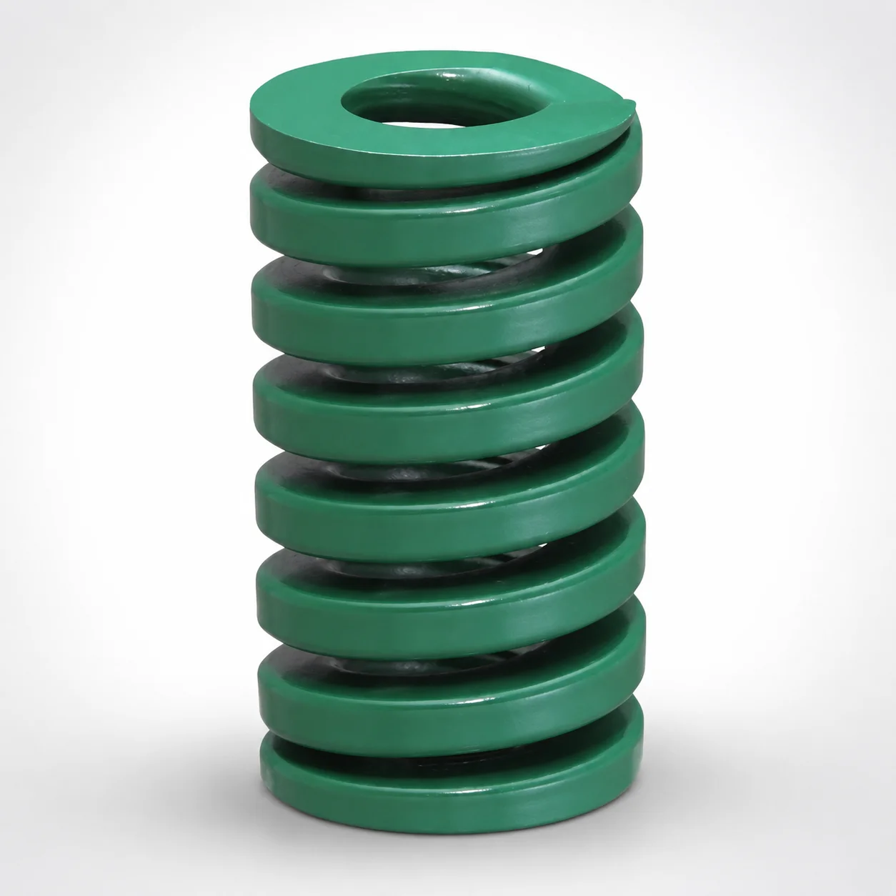
JIS Standard Heavy Duty Die Spring 24% Deflection
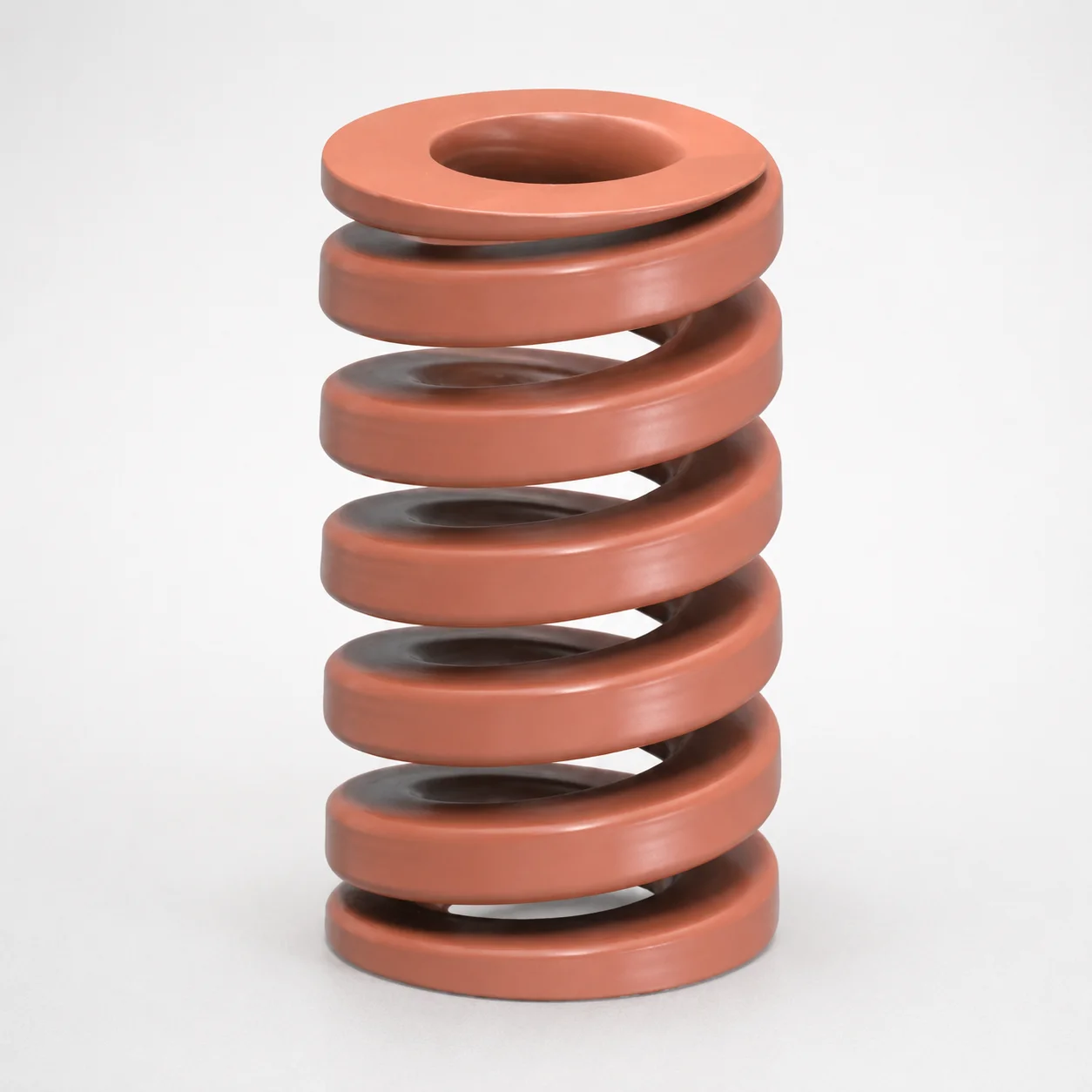
JIS Standard Chrome Silicon Oil-Tempered Wire Heavy Duty Die Spring 20% Deflection
Need Custom Specifications?
Our engineering team can help with custom configurations, material selection, and volume pricing.