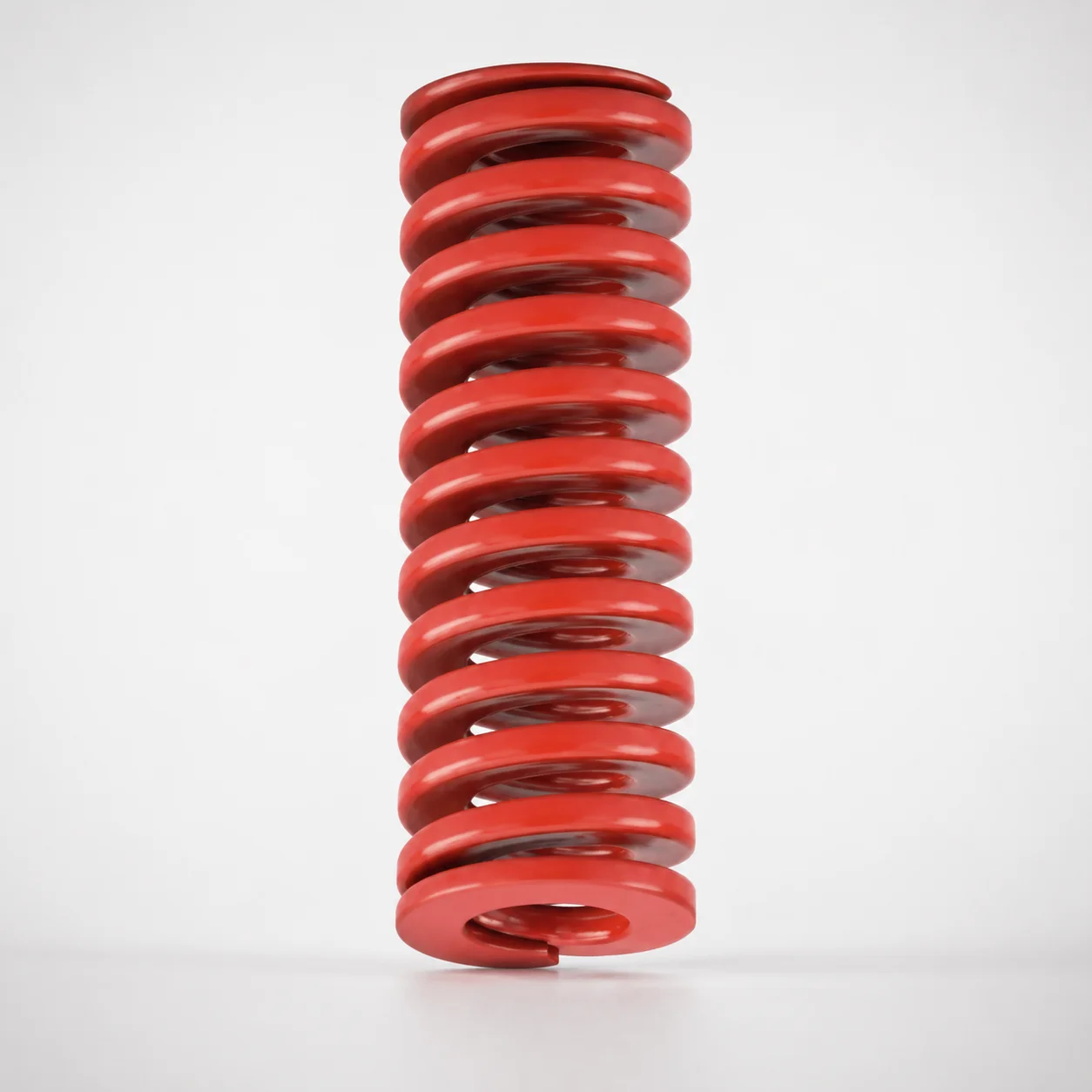
JIS Standard Chrome Silicon Medium Duty Die Spring - 32% Deflection
Medium Duty Die Spring - 32% Deflection is built for stable die return performance under controlled load conditions. Chrome silicon spring steel provides dependable resilience for medium duty tooling cycles.
- Medium-duty coil design tuned for 32% allowable deflection
- Chrome silicon material supports high fatigue resistance and long service life
- Designed for typical die spring installations with JIS compliance
- Commonly used in forming, stamping, and general die return applications
Specifications
201 configurations available
| type | Outer Diameter D (mm) | Length L (mm) | d (Inner diameter) (mm) |
|---|---|---|---|
| - | 10 | 20 | 5 |
| - | 10 | 25 | 5 |
| - | 10 | 30 | 5 |
| - | 10 | 35 | 5 |
| - | 10 | 40 | 5 |
| - | 10 | 45 | 5 |
| - | 10 | 50 | 5 |
| - | 10 | 55 | 5 |
| - | 10 | 60 | 5 |
| - | 10 | 65 | 5 |
| - | 10 | 70 | 5 |
| - | 10 | 75 | 5 |
| - | 10 | 80 | 5 |
| - | 12 | 20 | 6 |
| - | 12 | 25 | 6 |
| - | 12 | 30 | 6 |
| - | 12 | 35 | 6 |
| - | 12 | 40 | 6 |
| - | 12 | 45 | 6 |
| - | 12 | 50 | 6 |
| - | 12 | 55 | 6 |
| - | 12 | 60 | 6 |
| - | 12 | 65 | 6 |
| - | 12 | 70 | 6 |
| - | 12 | 75 | 6 |
| - | 12 | 80 | 6 |
| - | 14 | 25 | 7 |
| - | 14 | 30 | 7 |
| - | 14 | 35 | 7 |
| - | 14 | 40 | 7 |
| - | 14 | 45 | 7 |
| - | 14 | 50 | 7 |
| - | 14 | 55 | 7 |
| - | 14 | 60 | 7 |
| - | 14 | 65 | 7 |
| - | 14 | 70 | 7 |
| - | 14 | 75 | 7 |
| - | 14 | 80 | 7 |
| - | 14 | 90 | 7 |
| - | 16 | 100 | 8 |
| - | 16 | 25 | 8 |
| - | 16 | 30 | 8 |
| - | 16 | 35 | 8 |
| - | 16 | 40 | 8 |
| - | 16 | 45 | 8 |
| - | 16 | 50 | 8 |
| - | 16 | 55 | 8 |
| - | 16 | 60 | 8 |
| - | 16 | 65 | 8 |
| - | 16 | 70 | 8 |
Product Guide
Application Scenarios+
This die spring is used inside injection-mold tooling and forming/press stations where reliable die return under controlled load is required. Its medium-duty coil design is tuned to an allowable deflection of 32%, helping maintain repeatable return force during cycling.
Scenario 1: Automotive connector or bracket molding fixtures often use sprung ejector/actuation elements; this spring supports stable return behavior when the tooling sees moderate load swings.
Scenario 2: Appliance housings and general forming inserts benefit from consistent die return during frequent press cycles. The JIS-compliant configuration helps integrate predictably with standard die spring seats and installation practices.
Scenario 3: Short-to-medium stroke die protection and reset mechanisms where fatigue life matters. The chrome silicon chemistry is suited for forming/stamping tooling environments that demand durable resilience over many cycles.
- Medium duty tuning matches moderate loads rather than heavy continuous impact
- 32% deflection rating supports predictable force-versus-displacement behavior
- JIS compliance aids compatibility with conventional tooling designs
Material & Process Details+
These medium-duty die springs are made from chrome silicon spring steel, selected for high elastic resilience and strong fatigue resistance. Chrome silicon alloys typically balance wear and toughness, favoring long service life under repeated load rather than extreme plastic deformation.
Heat treatment for this class of die spring steel is commonly quenched and tempered to achieve spring-grade hardness and dimensional stability. Exact hardness and the specific tempering condition are not provided in the supplied data, so hardness values (HRC) must be verified from the manufacturing certificate for your batch.
- Fatigue resistance: High, supporting stable cycling and controlled deflection behavior
- Wear resistance: Adequate for moderate tooling contact conditions
- Toughness trade-off: Increasing hardness improves fatigue life but can reduce impact toughness if over-tempered
If multiple spring grades are offered by the supplier, compare by fatigue performance under your target deflection (32%) and expected cycle count. Ensure the seat design and spring free length accommodate the required working displacement.
Sizing & Selection Guide+
To select the correct spring, match your tooling’s required deflection and available space to the provided geometry ranges: Outer Diameter D = 10–60 mm, Inner Diameter d = 5–30 mm, and Length L = 20–300 mm.
Step 1: Confirm the installation envelope. Choose D so it clears the die pocket/retainer features while still fitting the spring guide or seat. Choose d to provide proper clearance for the guide pin, ejector stem, or load shaft without binding during travel.
Step 2: Set working stroke using the 32% allowable deflection characteristic. Ensure your available compression travel does not exceed the spring’s allowable deflection for the intended cycle count; otherwise, you risk reduced life and loss of return force.
- L (20–300 mm) should be selected to achieve the correct free-to-loaded height relationship
- Check fit/clearance around d for shaft misalignment and thermal expansion
- All dimensions listed are variable ranges; specific part dimensions within the range are configurable per order
Frequently Asked Questions
What does the 32% allowable deflection mean for die return force settings?+
Which dimensions (D, d, L) must match the tooling seat and guide for reliable cycling?+
Is this spring suitable for medium-duty forming/stamping die return in high-cycle applications?+
How does JIS compliance affect interchangeability with existing die spring components?+
Do I need to worry about heat treatment differences when comparing chrome silicon die springs?+
Related Products
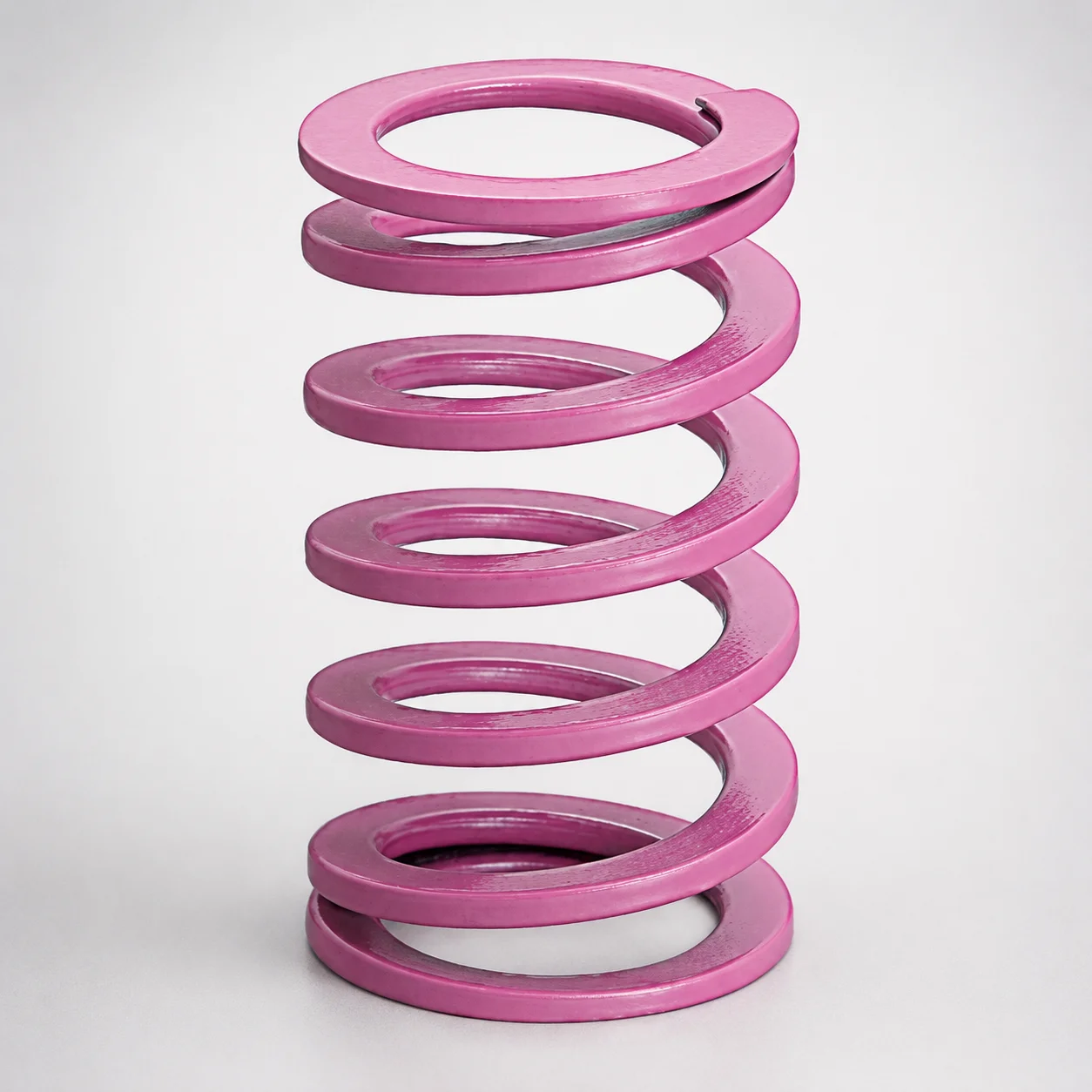
JIS Standard Chrome Silicon Medium Duty Die Spring 60% Deflection
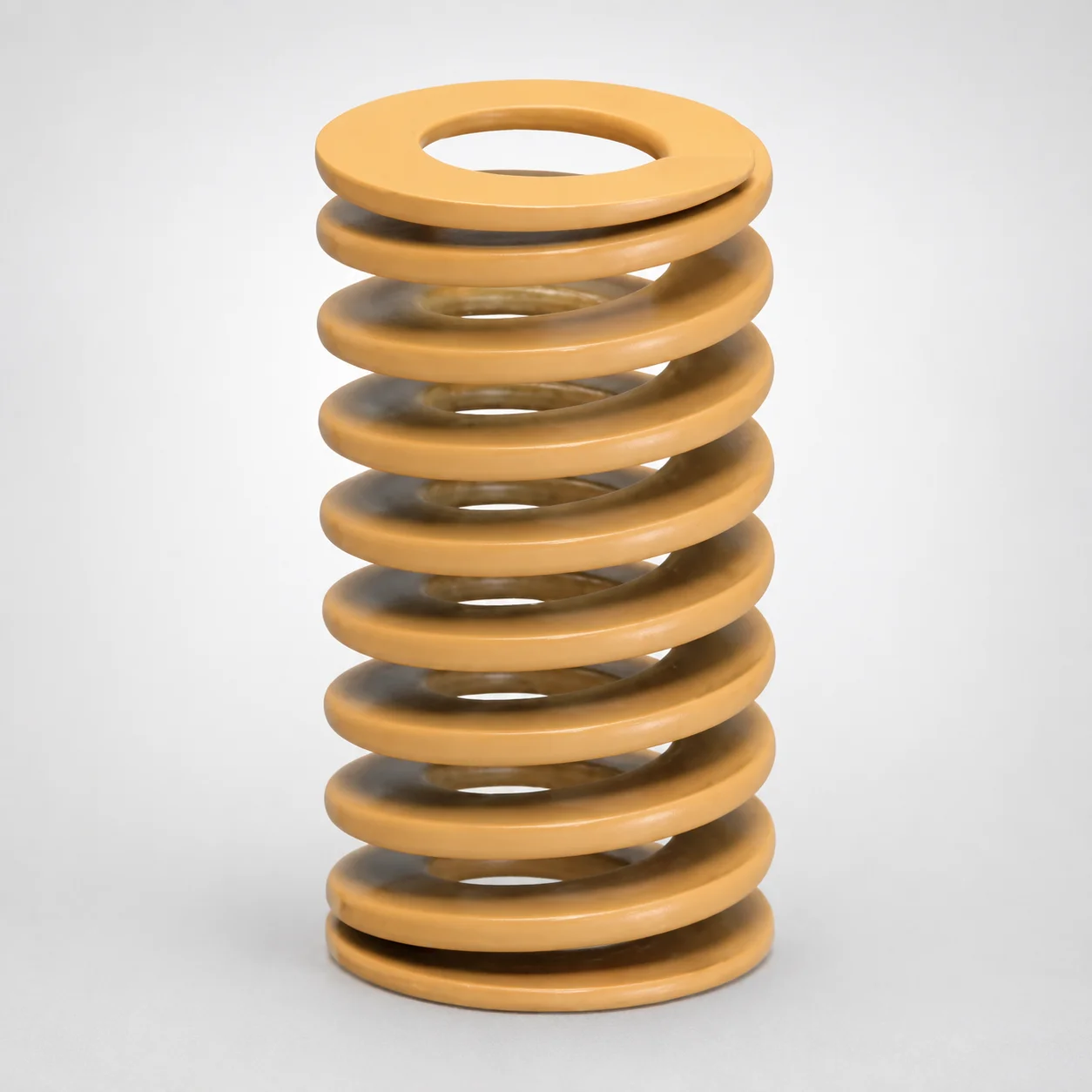
JIS Standard Chrome Silicon Medium Duty Die Spring - 50% Deflection
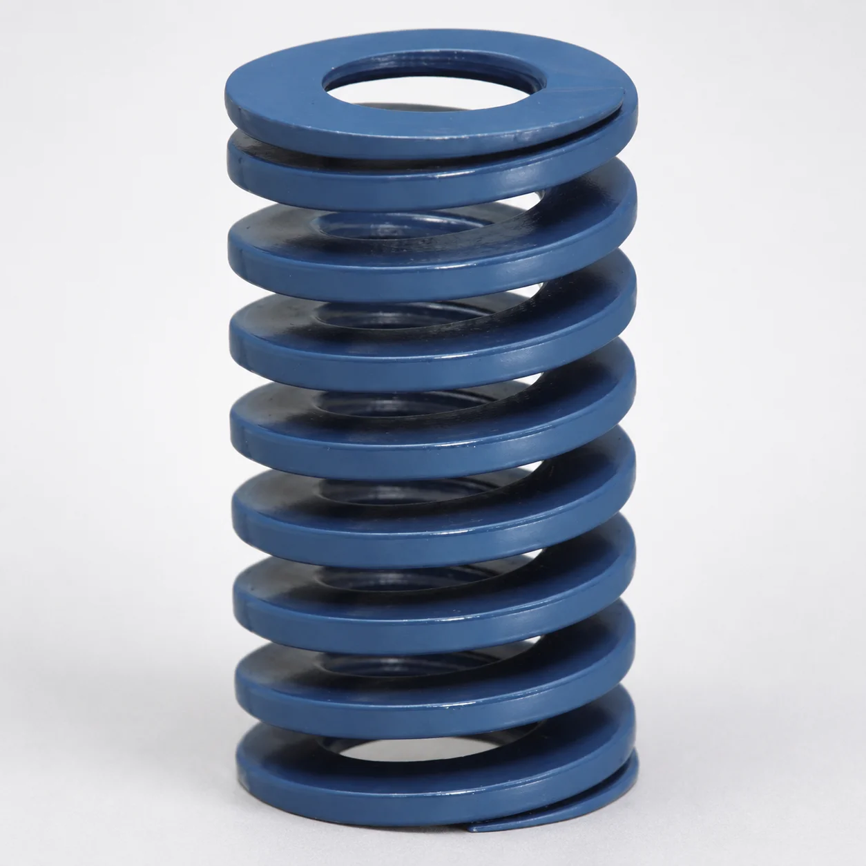
JIS Standard Chrome Silicon Steel Medium Duty Die Spring - 40% Deflection
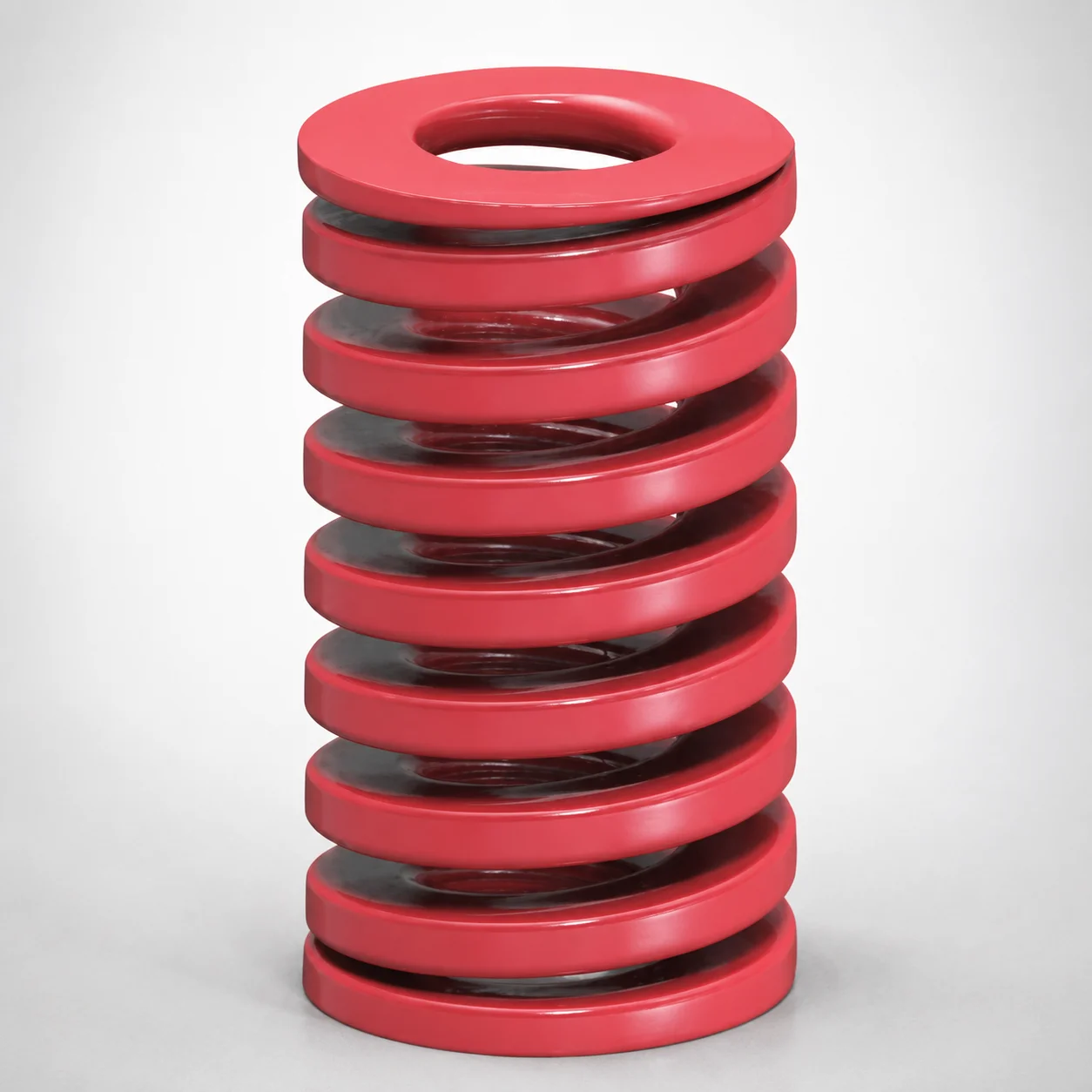
JIS Standard Medium Duty Die Spring 32% Deflection Chrome Silicon Coil Springs
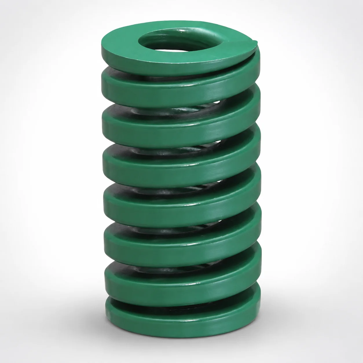
JIS Standard Heavy Duty Die Spring 24% Deflection
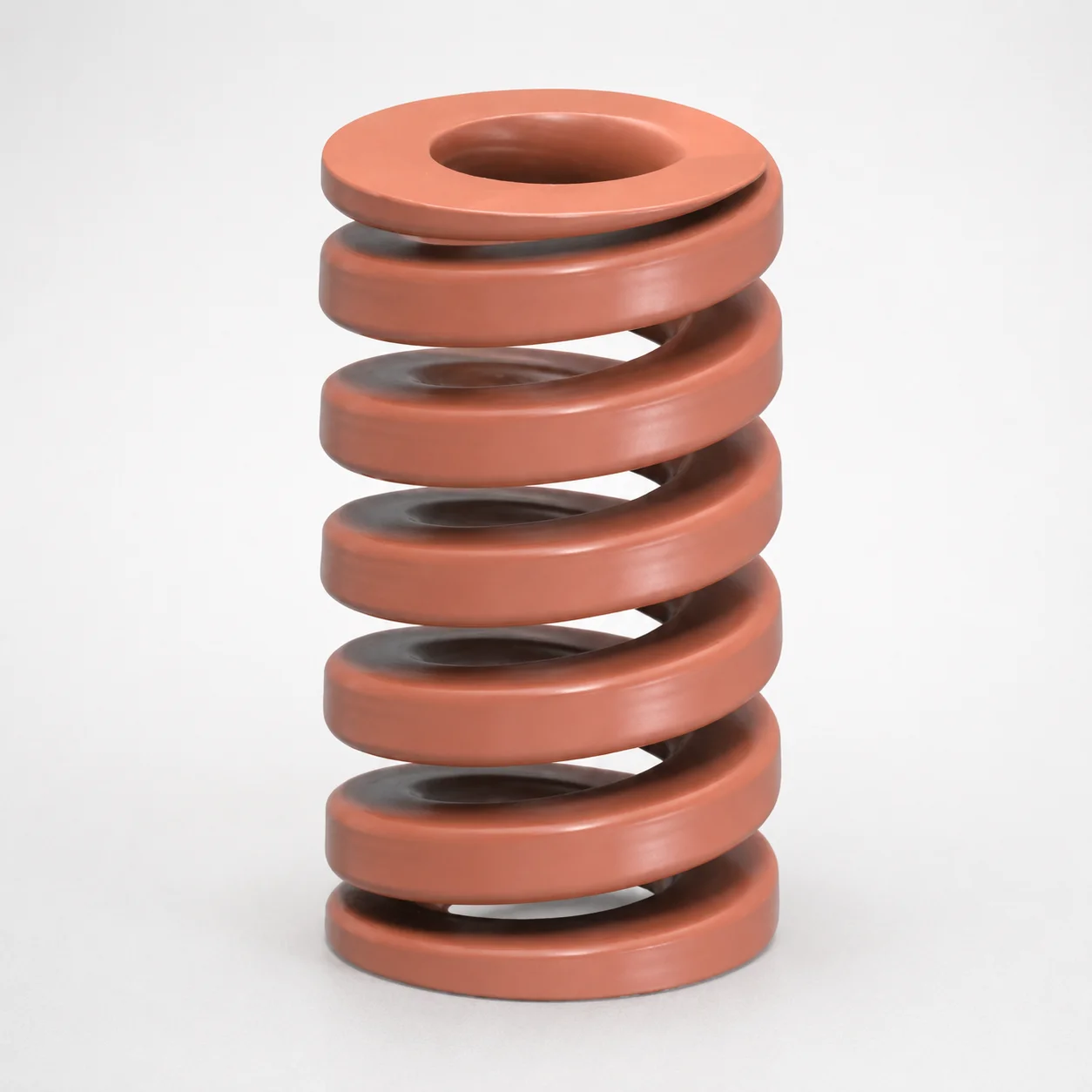
JIS Standard Chrome Silicon Oil-Tempered Wire Heavy Duty Die Spring 20% Deflection
Need Custom Specifications?
Our engineering team can help with custom configurations, material selection, and volume pricing.