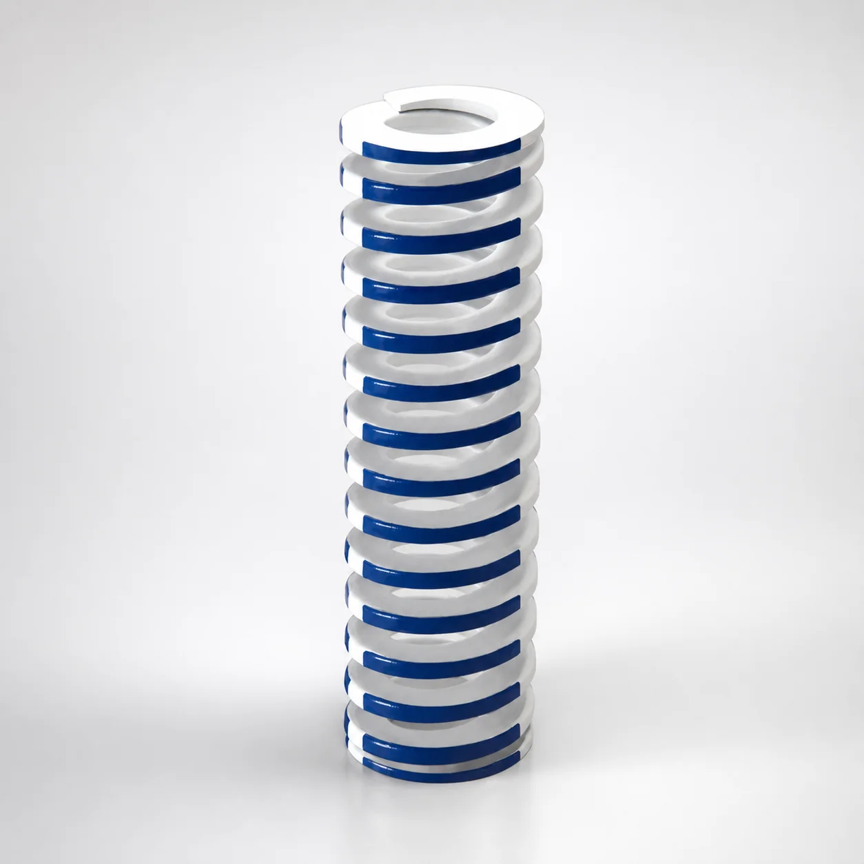
Inch Medium Duty Die Spring - 40% Deflection, Chrome Silicon
Inch Medium Duty Die Spring - 40% Deflection, Chrome Silicon from Lamina is built for stable load support in medium-duty die applications. The oil-tempered chrome silicon steel wire provides strong resilience for consistent spring performance.
- Medium-duty design at 40% deflection balances load and stroke control
- Made from chrome silicon steel (SWOSC-V equivalent) with durable oil-tempered wire
- Supports reliable operation across typical die spring requirements for press and tooling work
- Inch-series format for straightforward selection in U.S. standard die builds
Specifications
103 configurations available
| Outer Diameter D (in) | Length L (in) | Max. comp. length (in) | Rod Diameter (in) |
|---|---|---|---|
| 3/4" | 1-1/4" | 0.65" | 3/8" |
| 3/4" | 1" | 0.50" | 3/8" |
| 3/4" | 1-3/4" | 0.88" | 3/8" |
| 3/4" | 1-1/2" | 0.77" | 3/8" |
| 3/4" | 2" | 1.03" | 3/8" |
| 3/4" | 2-1/2" | 1.28" | 3/8" |
| 3/4" | 3" | 1.49" | 3/8" |
| 3/4" | 3-1/2" | 1.74" | 3/8" |
| 3/4" | 4" | 1.99" | 3/8" |
| 3/4" | 4-1/2" | 2.24" | 3/8" |
| 3/4" | 5" | 2.48" | 3/8" |
| 3/4" | 5-1/2" | 2.72" | 3/8" |
| 3/4" | 12" | 5.84" | 3/8" |
| 3/4" | 6-1/2" | 3.20" | 3/8" |
| 3/4" | 7-1/2" | 3.64" | 3/8" |
| 3/4" | 6" | 2.97" | 3/8" |
| 1" | 1-1/4" | 0.66" | 1/2" |
| 1" | 1" | 0.51" | 1/2" |
| 1" | 1-3/4" | 0.90" | 1/2" |
| 1" | 1-1/2" | 0.78" | 1/2" |
| 1" | 2" | 1.02" | 1/2" |
| 1" | 2-1/2" | 1.27" | 1/2" |
| 1" | 3" | 1.50" | 1/2" |
| 1" | 3-1/2" | 1.75" | 1/2" |
| 1" | 4" | 2.00" | 1/2" |
| 1" | 4-1/2" | 2.25" | 1/2" |
| 1" | 5" | 2.49" | 1/2" |
| 1" | 5-1/2" | 2.74" | 1/2" |
| 1" | 6" | 2.96" | 1/2" |
| 1" | 7" | 3.48" | 1/2" |
| 1" | 12" | 5.76" | 1/2" |
| 1" | 8" | 3.86" | 1/2" |
| 1-1/4" | 1-3/4" | 0.88" | 5/8" |
| 1-1/4" | 1-1/2" | 0.75" | 5/8" |
| 1-1/4" | 2" | 1.05" | 5/8" |
| 1-1/4" | 2-1/2" | 1.25" | 5/8" |
| 1-1/4" | 3" | 1.46" | 5/8" |
| 1-1/4" | 3-1/2" | 1.70" | 5/8" |
| 1-1/4" | 4" | 1.95" | 5/8" |
| 1-1/4" | 4-1/2" | 2.20" | 5/8" |
| 1-1/4" | 5" | 2.44" | 5/8" |
| 1-1/4" | 5-1/2" | 2.72" | 5/8" |
| 1-1/4" | 6" | 2.98" | 5/8" |
| 1-1/4" | 7" | 3.50" | 5/8" |
| 1-1/4" | 8" | 3.98" | 5/8" |
| 1-1/4" | 12" | 5.98" | 5/8" |
| 1-1/4" | 10" | 4.98" | 5/8" |
| 1-1/2" | 2" | 1.03" | 3/4" |
| 1-1/2" | 2-1/2" | 1.27" | 3/4" |
| 1-1/2" | 3" | 1.52" | 3/4" |
Product Guide
Application Scenarios+
These inch-format medium-duty die springs are used in injection mold tooling where a return or clamping force must remain stable under frequent cycling. Typical applications include mold core/cavity lifters and stripper assemblies, where the spring supports a controlled retraction stroke after part ejection. The 40% deflection rating helps balance working load and available travel, reducing the risk of premature fatigue during repetitive duty cycles.
They are also well-suited for press-fit or spring-loaded die mechanisms within molding systems, including slides and tooling supports that require consistent load over a mid-range spring range. For these builds, the chrome silicon steel wire’s resilience and oil-tempered construction improve recovery after compression, aiding repeatable actuation.
In addition, these springs are practical in small-to-medium die housings and tooling stations using U.S. inch component sizing, enabling straightforward replacement and standard selection for medium-duty load requirements.
Material & Process Details+
The spring is made from chrome silicon steel wire (described as SWOSC-V equivalent), selected for its good resilience and wear-related durability in cyclic die applications. Oil-tempered wire provides a favorable balance of toughness and fatigue resistance, supporting repeated compression cycles without rapid loss of spring performance.
- Heat treatment / condition: oil-tempered chrome silicon steel wire (medium-duty spring stock condition).
- Hardness: no HRC value is provided in the available data; hardness is therefore not specified here.
- Property trade-offs: chrome silicon steel prioritizes elastic recovery and fatigue life; very high hardness is generally not the goal for die springs because toughness and stress relaxation resistance are critical.
Compared with lower-alloy or plain carbon spring wire, chrome silicon steel typically offers improved resilience for medium-duty load support, while oil tempering helps maintain consistent spring characteristics in service.
Sizing & Selection Guide+
Select the spring based on the required free-to-working space in the die stack and the intended compression range. Use Outer Diameter D (in) = 1 ~ 5 to fit within the available spring pocket and surrounding guide clearances. Then choose the Length L (in) = 1 ~ 12 to match the installed free length needed for your stroke and preload design.
- Rod/inner guidance sizing: ensure compatibility with the Rod Diameter (in) = 1 ~ 11 that will interface with the spring assembly.
- Working compression check: verify the expected compression falls within the provided Max. comp. length = 0.45 ~ 6.17 range for your design envelope.
- Deflection strategy: this variant is specified for 40% deflection, so target operation at or below the intended working deflection to maintain consistent load and extend fatigue life.
Because tolerance values are not provided in the data, confirm fit by checking assembly clearances and allowable stack-up variation using your mold’s drawing standards.
Frequently Asked Questions
How do I verify that this medium-duty die spring will fit my mold stack and not bottom out during ejection?+
Use Outer Diameter D (1 ~ 5 in) to confirm the spring fits within the spring pocket and surrounding tooling clearance. Select Length L (1 ~ 12 in) to match your installed free length, then compare your expected compression to the given Max. comp. length (0.45 ~ 6.17 in) to prevent bottoming.
If your operating compression approaches the max range, redesign the stack-up or choose a different spring length to keep working within the intended deflection window.
What does “40% deflection” imply for load stability in cyclic die applications?+
This variant is engineered for 40% deflection, which is used to size the spring so it provides a balanced relationship between load level and stroke control in medium-duty applications.
For consistent performance, the spring should be expected to operate near the design deflection target rather than being repeatedly compressed toward the maximum capability.
Is the chrome silicon material oil-tempered, and what does that mean for fatigue performance?+
The description specifies oil-tempered chrome silicon steel wire (chrome silicon, with SWOSC-V equivalent). Oil tempering is intended to support elastic recovery and cyclic resilience, which is important for die springs used repeatedly in cycling mold mechanisms.
No hardness (HRC) figure is provided in the available specifications, so hardness-based compatibility checks should rely on your project’s design criteria rather than a published HRC value.
How should I choose the rod/inner interface diameter when using this spring in a guided assembly?+
Match the assembly interface to the available Rod Diameter (1 ~ 11 in) range from the specifications. Ensure the rod/spring assembly clearance is compatible with the mold’s guide and alignment requirements so the spring can compress without binding.
If the rod diameter is near the extremes of the range, re-check pocket clearances and installation space to accommodate manufacturing stack-up.
What dimensional parameters are configurable versus fixed for this inch-series die spring?+
This series provides multiple selectable variants across D = 1 ~ 5 in, L = 1 ~ 12 in, Max. comp. length = 0.45 ~ 6.17 in, and Rod diameter = 1 ~ 11 in. The provided data does not indicate fixed single values for these dimensions, so selection depends on the configuration you choose from the series.
The spring’s functional target of 40% deflection and the stated chrome silicon (SWOSC-V equivalent) material are the defining fixed characteristics for this variant.
Related Products
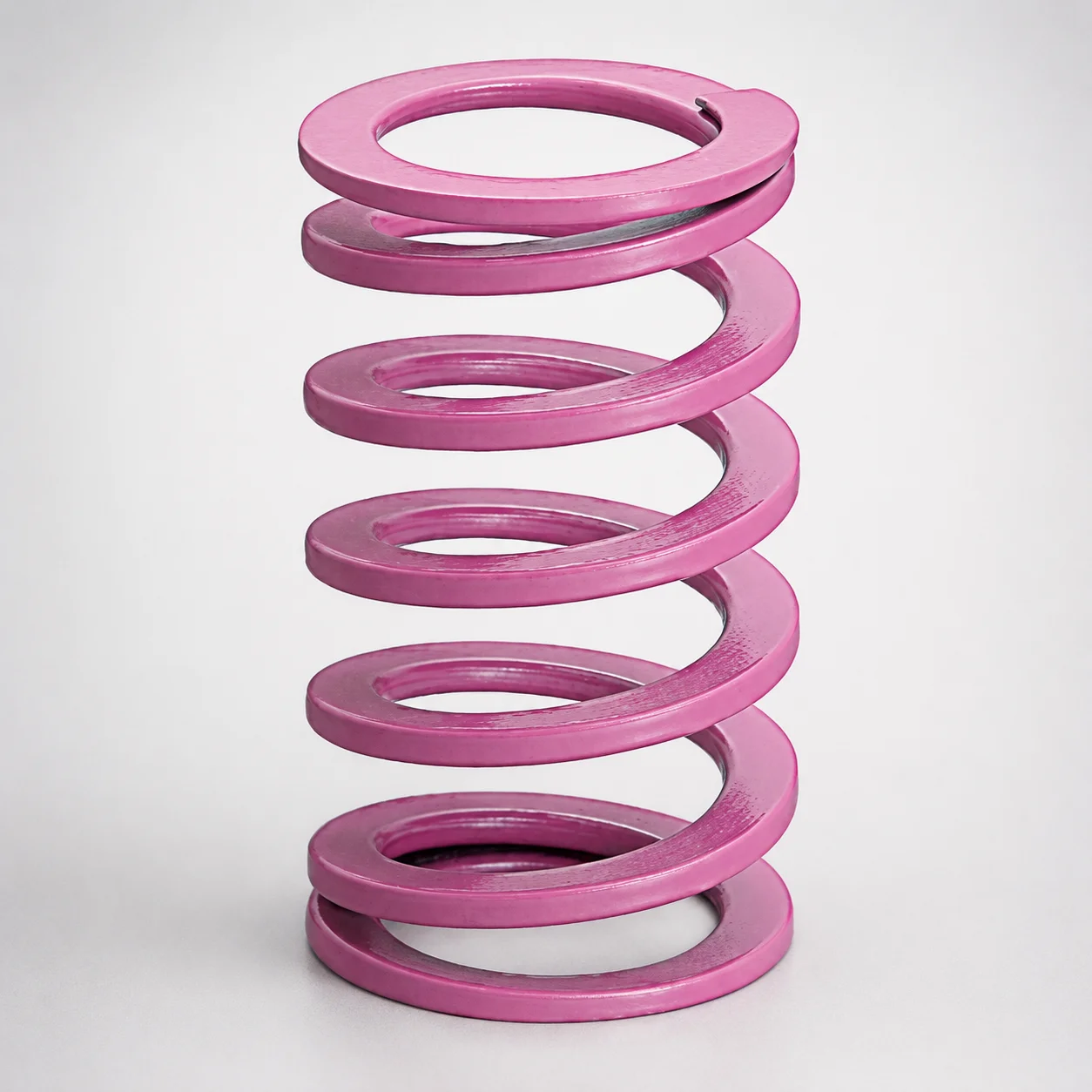
JIS Standard Chrome Silicon Medium Duty Die Spring 60% Deflection
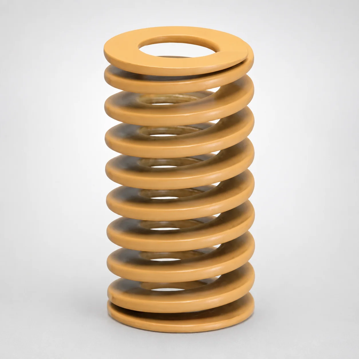
JIS Standard Chrome Silicon Medium Duty Die Spring - 50% Deflection
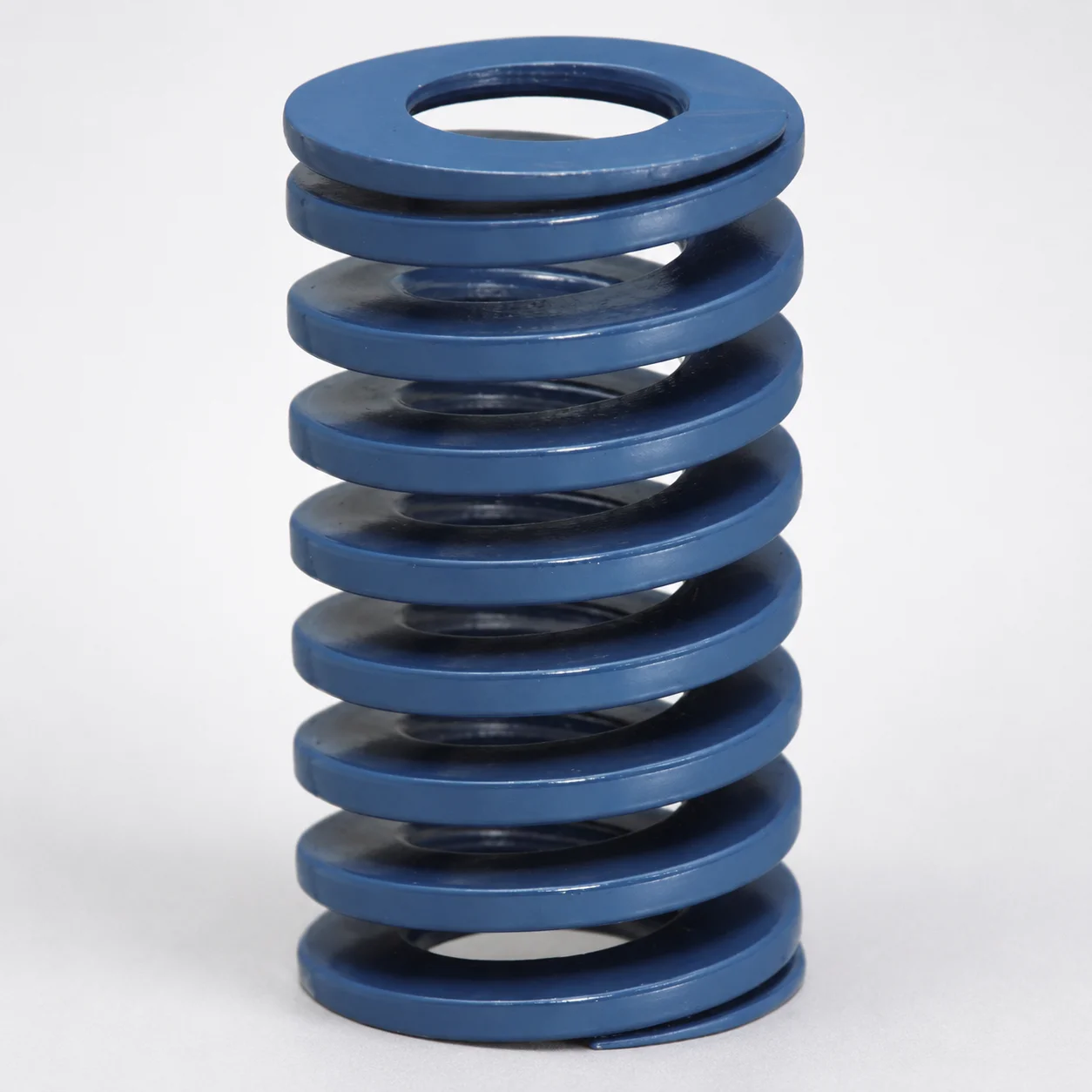
JIS Standard Chrome Silicon Steel Medium Duty Die Spring - 40% Deflection
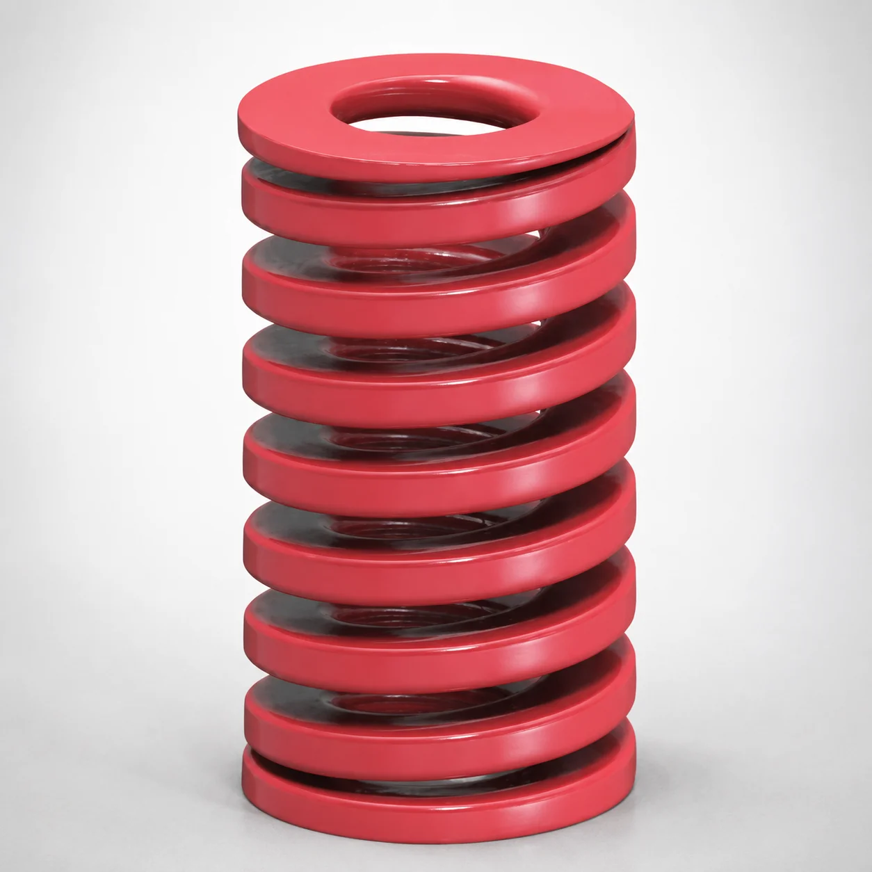
JIS Standard Medium Duty Die Spring 32% Deflection Chrome Silicon Coil Springs
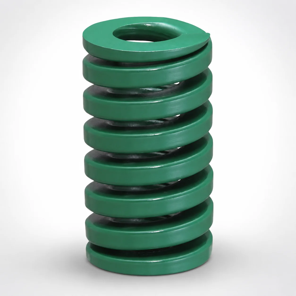
JIS Standard Heavy Duty Die Spring 24% Deflection
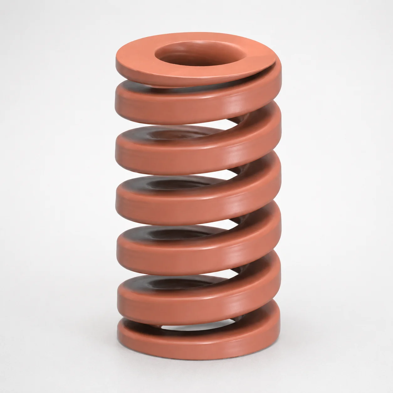
JIS Standard Chrome Silicon Oil-Tempered Wire Heavy Duty Die Spring 20% Deflection
Need Custom Specifications?
Our engineering team can help with custom configurations, material selection, and volume pricing.