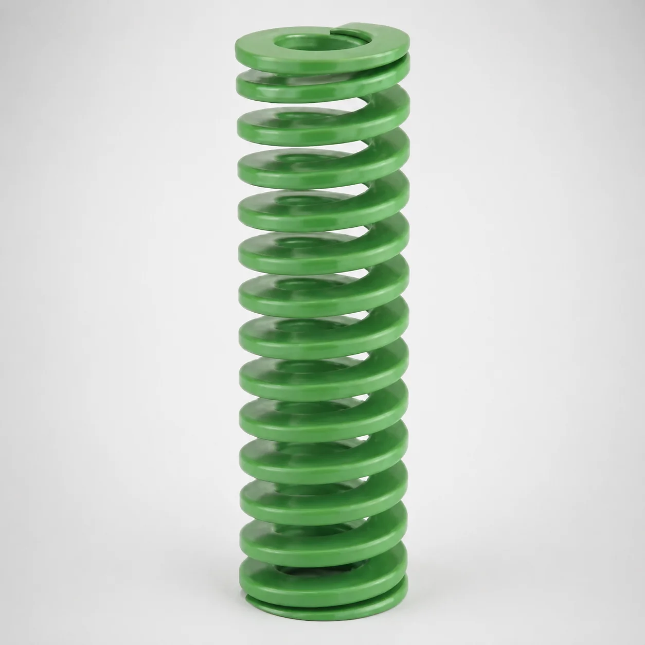
Light Load Round Wire Die Spring - 40% Deflection
Light Load Round Wire Die Spring - 40% Deflection is designed for inch die sets requiring controlled spring response and reliable return force. Its light-duty profile helps maintain consistent press performance during repeated cycling.
- Round wire construction tuned for 40% allowable deflection ratio
- Chrome-silicon style spring steel for dependable wear resistance
- Accepts inch-system fit with optional 3/8", 1/2", 5/8" outer diameters
- Commonly used in progressive and stamping die applications needing light load control
Specifications
30 configurations available
| Outer Diameter D (in) | Length L (in) | d (Inner diameter) (in) |
|---|---|---|
| 3/8" | 3/4" | 3/16" |
| 3/8" | 1" | 3/16" |
| 3/8" | 1-1/4" | 3/16" |
| 3/8" | 1-1/2" | 3/16" |
| 3/8" | 1-3/4" | 3/16" |
| 3/8" | 2" | 3/16" |
| 3/8" | 2-1/2" | 3/16" |
| 3/8" | 3" | 3/16" |
| 3/8" | 12" | 3/16" |
| 1/2" | 3/4" | 9/32" |
| 1/2" | 1" | 9/32" |
| 1/2" | 1-1/4" | 9/32" |
| 1/2" | 1-1/2" | 9/32" |
| 1/2" | 1-3/4" | 9/32" |
| 1/2" | 2" | 9/32" |
| 1/2" | 2-1/2" | 9/32" |
| 1/2" | 3" | 9/32" |
| 1/2" | 3-1/2" | 9/32" |
| 1/2" | 12" | 9/32" |
| 5/8" | 3/4" | 11/32" |
| 5/8" | 1" | 11/32" |
| 5/8" | 1-1/4" | 11/32" |
| 5/8" | 1-1/2" | 11/32" |
| 5/8" | 1-3/4" | 11/32" |
| 5/8" | 2" | 11/32" |
| 5/8" | 2-1/2" | 11/32" |
| 5/8" | 3" | 11/32" |
| 5/8" | 3-1/2" | 11/32" |
| 5/8" | 4" | 11/32" |
| 5/8" | 12" | 11/32" |
Product Guide
Application Scenarios+
This light-duty die spring is used inside inch-system die assemblies where you need controlled return force without overloading the die set during repeated cycling. It’s especially suited to progressive and stamping dies that demand stable part ejection/stripper return over many strokes, benefiting from a consistent 40% allowable deflection ratio.
In automotive connector and terminal stamping lines, the spring’s round-wire geometry helps provide predictable spring response as the press cycles, reducing variability that can affect feeding and formed feature accuracy.
- Progressive/stamping die return: tuned for light load with controlled travel (40% deflection allowance).
- Inch die setups: built for inch-system fit using specified outer diameter options (3/8", 1/2", 5/8").
Its chrome-silicon construction supports reliable die return under wear conditions typical of high-cycle tooling.
Material & Process Details+
The spring is described as a chrome-silicon style spring steel intended for dependable wear resistance and stable return force in die tooling. Chrome-silicon steels are commonly selected for springs because they can maintain elasticity under cyclic loading better than plain carbon spring steels.
- Expected property focus: improved fatigue resistance and wear durability for die return applications.
- Hardness/heat treatment: no specific HRC value or heat-treatment state is provided in the available data, so hardness should be verified from the manufacturer’s material certificate for your lot.
- Trade-off: increased alloying typically improves fatigue/wear performance, but spring steel still requires careful heat treatment to balance toughness and allowable deflection.
For close design control, confirm the exact chrome-silicon specification and heat-treatment process used by the supplier, since these details directly affect fatigue life at the selected deflection level.
Sizing & Selection Guide+
Correct sizing begins with matching the die assembly’s required travel and installing dimensions. This spring is specified with an outer diameter D of 3/8", 1/2", or 5/8" and an available length L range of 1 to 12 inches.
To select the right variant, choose:
- D (outer diameter): match the spring pocket/guide clearance in your inch die set using 3/8", 1/2", or 5/8".
- d (inner diameter): verify the listed inner diameter options of 3/16", 9/32", or 11/32" are compatible with the surrounding guide/center elements.
- L (length): pick the closest available length within 1–12 in to achieve the required installed stack height and working deflection.
Design around the stated 40% allowable deflection ratio: the working deflection should not exceed 40% of the spring’s rated deflection capability to maintain return reliability and avoid premature fatigue. If your die pocket uses tight clearances, account for manufacturing tolerances on D, d, and L during fit-up.
Frequently Asked Questions
How do I use the 40% deflection ratio when designing a light-load die return?+
Which outer diameter (D) options are available for inch die assemblies?+
What inner diameter (d) values are compatible with guide/center features?+
How should I choose the spring length (L) from the 1–12 inch range?+
What material properties should I verify for fatigue life, given the chrome-silicon description?+
Related Products
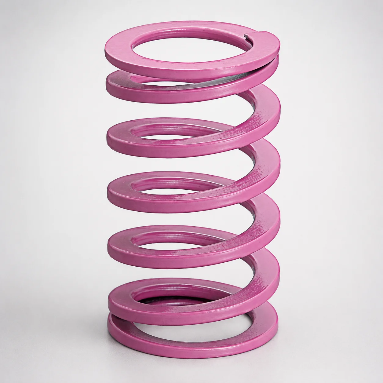
JIS Standard Chrome Silicon Medium Duty Die Spring 60% Deflection
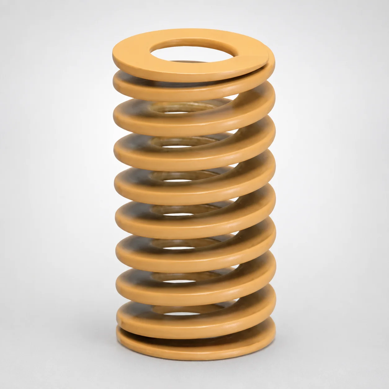
JIS Standard Chrome Silicon Medium Duty Die Spring - 50% Deflection
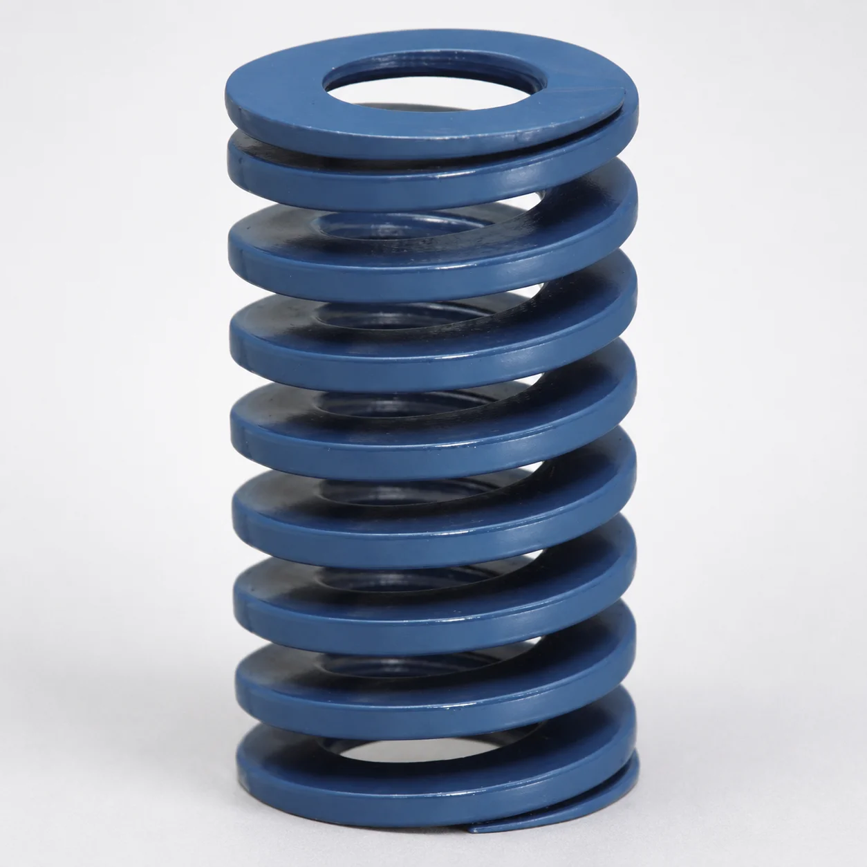
JIS Standard Chrome Silicon Steel Medium Duty Die Spring - 40% Deflection
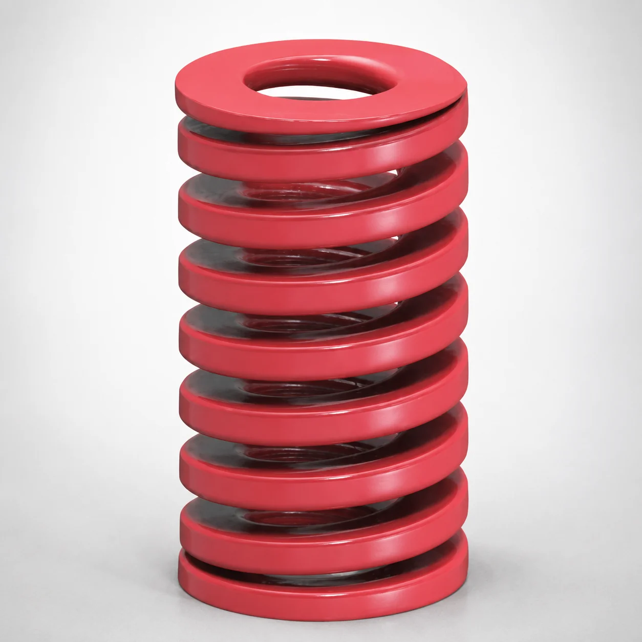
JIS Standard Medium Duty Die Spring 32% Deflection Chrome Silicon Coil Springs
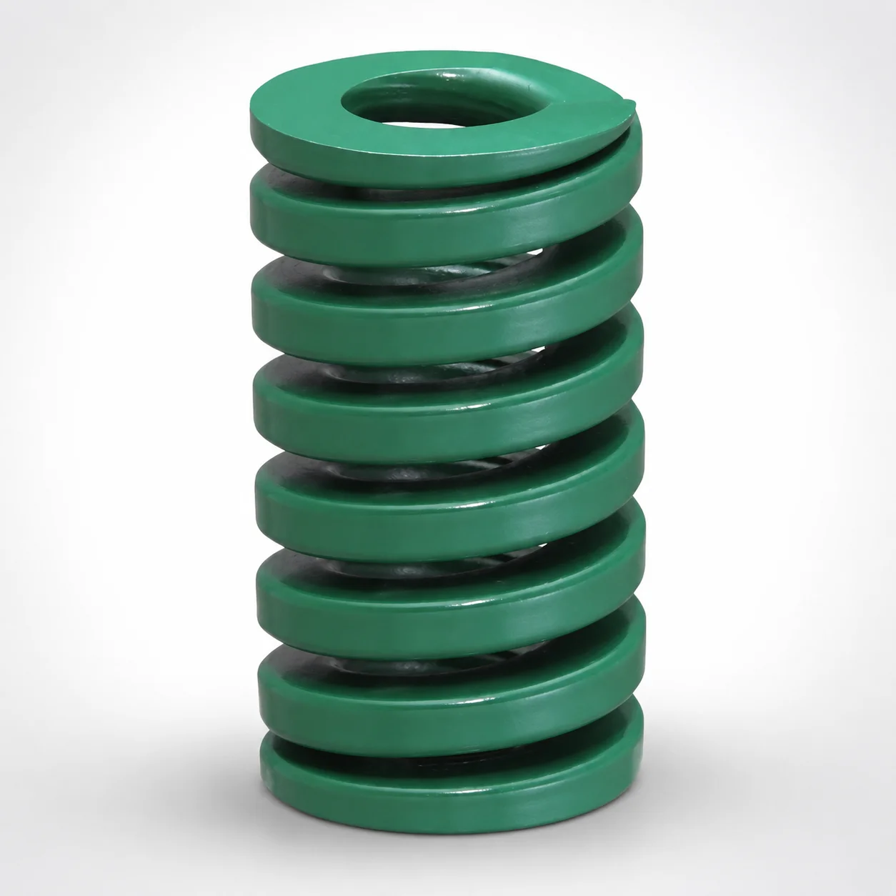
JIS Standard Heavy Duty Die Spring 24% Deflection
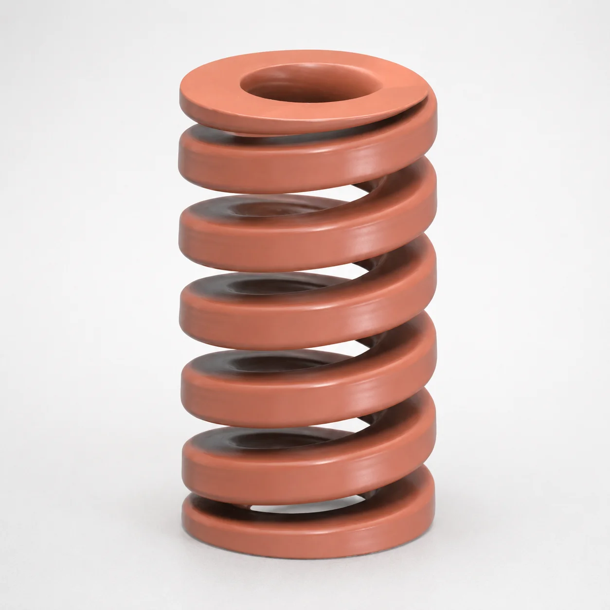
JIS Standard Chrome Silicon Oil-Tempered Wire Heavy Duty Die Spring 20% Deflection
Need Custom Specifications?
Our engineering team can help with custom configurations, material selection, and volume pricing.