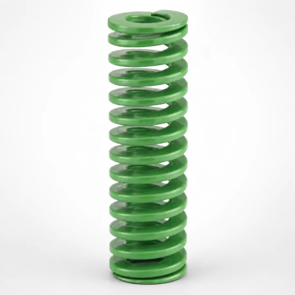
DieMax XL™ Light Duty Die Spring 40% Deflection Chrome Silicon (Inch)
DieMax XL™ light duty die spring 40% deflection (Chrome Silicon, Inch) is built for light-load die support where stable force and controlled deflection improve repeatable motion. It helps damp vibration and protect sensitive components during industrial forming and automation.
- Optimized 40% deflection for reliable support under light load conditions
- Chrome silicon construction improves spring durability and shock absorption
- Inch dimensions support consistent installation in standard die spring stations
- Typical use in press dies, forming tools, and automation parts handling
Specifications
111 configurations available
| type | Outer Diameter D (in) | Length L (in) | d (Inner diameter) (in) |
|---|---|---|---|
| - | 3/8" | 3/4" | 3/16" |
| - | 3/8" | 1" | 3/16" |
| - | 3/8" | 1-1/4" | 3/16" |
| - | 3/8" | 1-1/2" | 3/16" |
| - | 3/8" | 1-3/4" | 3/16" |
| - | 3/8" | 2" | 3/16" |
| - | 3/8" | 2-1/2" | 3/16" |
| - | 3/8" | 3" | 3/16" |
| - | 3/8" | 12" | 3/16" |
| - | 1/2" | 3/4" | 9/32" |
| - | 1/2" | 1" | 9/32" |
| - | 1/2" | 1-1/4" | 9/32" |
| - | 1/2" | 1-1/2" | 9/32" |
| - | 1/2" | 1-3/4" | 9/32" |
| - | 1/2" | 2" | 9/32" |
| - | 1/2" | 2-1/2" | 9/32" |
| - | 1/2" | 3" | 9/32" |
| - | 1/2" | 3-1/2" | 9/32" |
| - | 1/2" | 12" | 9/32" |
| - | 5/8" | 3/4" | 11/32" |
| - | 5/8" | 1" | 11/32" |
| - | 5/8" | 1-1/4" | 11/32" |
| - | 5/8" | 1-1/2" | 11/32" |
| - | 5/8" | 1-3/4" | 11/32" |
| - | 5/8" | 2" | 11/32" |
| - | 5/8" | 2-1/2" | 11/32" |
| - | 5/8" | 3" | 11/32" |
| - | 5/8" | 3-1/2" | 11/32" |
| - | 5/8" | 4" | 11/32" |
| - | 5/8" | 12" | 11/32" |
| - | 3/4" | 3/4" | 3/8" |
| - | 3/4" | 1" | 3/8" |
| - | 3/4" | 1-1/4" | 3/8" |
| - | 3/4" | 1-1/2" | 3/8" |
| - | 3/4" | 1-3/4" | 3/8" |
| - | 3/4" | 2" | 3/8" |
| - | 3/4" | 2-1/2" | 3/8" |
| - | 3/4" | 3" | 3/8" |
| - | 3/4" | 3-1/2" | 3/8" |
| - | 3/4" | 4" | 3/8" |
| - | 3/4" | 4-1/2" | 3/8" |
| - | 3/4" | 5" | 3/8" |
| - | 3/4" | 5-1/2" | 3/8" |
| - | 3/4" | 6" | 3/8" |
| - | 3/4" | 12" | 3/8" |
| - | 1" | 1" | 1/2" |
| - | 1" | 1-1/4" | 1/2" |
| - | 1" | 1-1/2" | 1/2" |
| - | 1" | 1-3/4" | 1/2" |
| - | 1" | 2" | 1/2" |
Product Guide
Application Scenarios+
This light-load die spring variant is used in injection mold tooling where a moving component must be supported with predictable compliance. In stripper plate and ejector return areas, the 40% deflection characteristic helps maintain consistent contact force while accommodating small dimensional changes and preventing chatter.
It also suits light-load forming and automation press tooling that interfaces with mold tooling, such as fixtures that feed parts or retract mechanisms. The chrome silicon design supports controlled deflection under vibration, improving repeatability during frequent cycling.
- Stripper/ejector return support: stable force with controlled compliance to reduce vibration and stick-slip effects.
- Light-load press and forming stations: damps shocks during intermittent contact without over-springing.
- Automation parts handling interfaces: helps protect sensitive components by absorbing dynamic loads.
Material & Process Details+
DieMax XL™ light duty die springs are made from chrome silicon, a spring steel alloy selected for strong wear and fatigue performance under cyclic loading. Chrome silicon chemistry enhances hardenability and improves resistance to stress relaxation compared with simpler carbon spring grades.
For die spring applications, springs are typically supplied heat-treated for high hardness, then tempered to balance stiffness and toughness. This heat treatment approach targets high fatigue strength while maintaining sufficient toughness to avoid brittle failure during rapid deflection cycles.
- Hardness & trade-off: higher hardness improves wear resistance and fatigue life, while tempering is used to protect toughness.
- Wear resistance: chrome silicon improves durability under vibration and repeated impact-like loading.
- Material comparison: relative to basic carbon spring steels, chrome silicon generally offers better fatigue durability and more stable force over service life.
Sizing & Selection Guide+
Select the spring dimensions to match your die spring pocket and guide clearances while achieving the intended deflection-to-force behavior for the load case. Use the provided ranges: Outer Diameter D = 1 ~ 5 in, Length L = 1 ~ 12 in, and Inner diameter d = 1 ~ 11 in.
- Check OD D: verify D fits the die spring station or housing bore without binding. Ensure adequate clearance for alignment through the stroke.
- Match free length L: choose L to achieve the design working deflection (40% deflection variant) within the available stack height and die open/close travel.
- Confirm ID d: ensure d accommodates the guide post or core feature diameter with the required radial clearance for motion and lubrication.
Tolerance/fit: because only nominal ranges are provided, confirm final fit with your die station tolerances (especially for D and d) to prevent side loading. These dimensions are configurable within the stated ranges; the 40% deflection characteristic is the fixed functional variant.
Frequently Asked Questions
How do I choose the correct Outer Diameter (D) for a die spring station in an injection mold build?+
Use the specified range D = 1 ~ 5 in and confirm the spring’s OD fits the die spring pocket without rubbing. Verify that the station allows proper alignment over the stroke, since side loading can increase stress during cycles.
Also ensure the selected D provides sufficient clearance for any retainers, housings, or guide structures used in your die design.
What Length (L) should I select to target the 40% deflection operating window?+
Select a free length within L = 1 ~ 12 in so that, at the designed die position, the spring operates around the 40% deflection behavior for this light-duty variant. Confirm available stack height and stroke so the spring is neither under-deflected (insufficient force) nor over-deflected (risk of reduced life).
Because only length ranges are provided, validate against your specific motion and clearance constraints.
How should I verify compatibility of the Inner Diameter (d) with a guide post or core feature?+
Confirm the inner diameter falls within d = 1 ~ 11 in and check that it clears the guide post/core feature diameter with appropriate radial clearance. The goal is smooth motion without interference, which helps avoid uneven loading and vibration.
If your design includes lubrication or coatings on the guide features, consider their thickness when checking fit.
Why is this chrome silicon (Inch) die spring suitable for vibration damping in light-load tooling?+
Chrome silicon spring steel is chosen for durable cyclic performance, helping maintain controlled deflection under repeated loading. The spring’s 40% deflection focus supports stable compliance for light loads where vibration damping improves repeatability.
In practice, it helps protect sensitive die components by absorbing dynamic effects during frequent cycles.
What heat-treatment state should I assume when comparing this spring to other spring steels?+
This product is specified as Chrome Silicon (Inch), which is commonly heat-treated and tempered to balance hardness and toughness for fatigue life. When comparing materials, focus on the trade-off: higher hardness can improve wear and fatigue strength, while tempering helps maintain toughness to resist brittle failure.
If you need the exact HRC and heat-treatment recipe for qualification, request the latest material certificate for the series code 250301196974.
Related Products
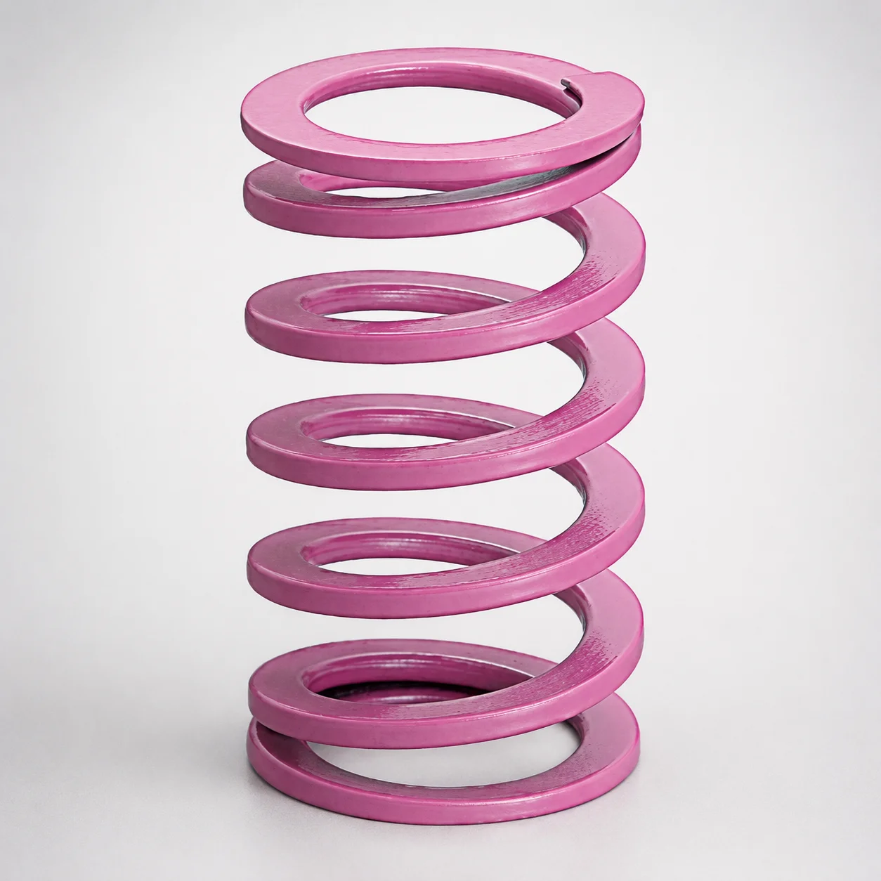
JIS Standard Chrome Silicon Medium Duty Die Spring 60% Deflection
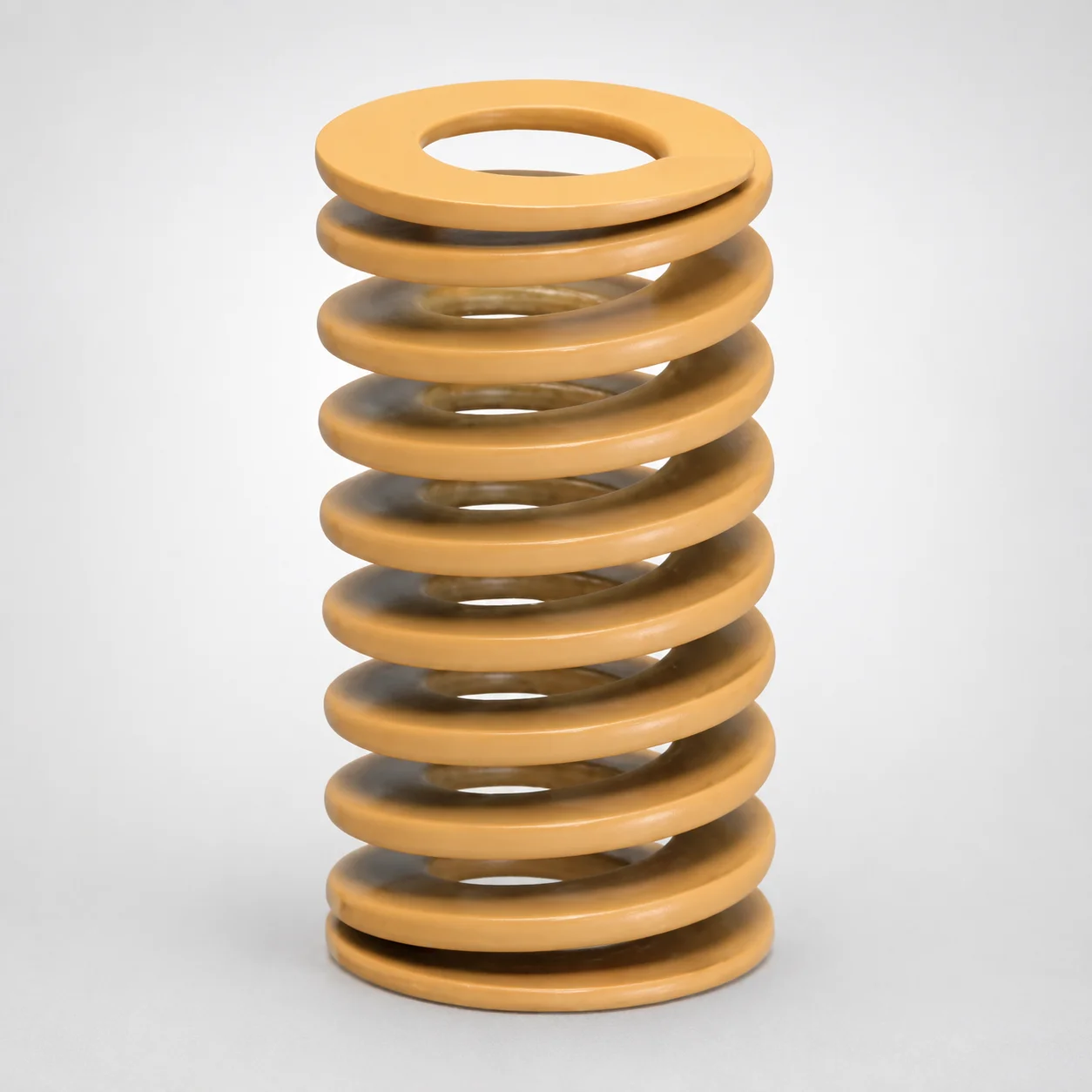
JIS Standard Chrome Silicon Medium Duty Die Spring - 50% Deflection
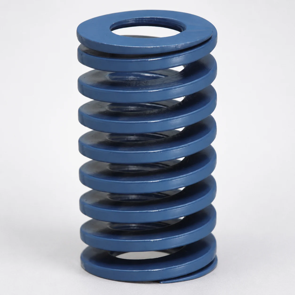
JIS Standard Chrome Silicon Steel Medium Duty Die Spring - 40% Deflection
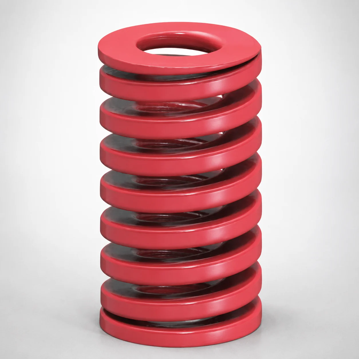
JIS Standard Medium Duty Die Spring 32% Deflection Chrome Silicon Coil Springs
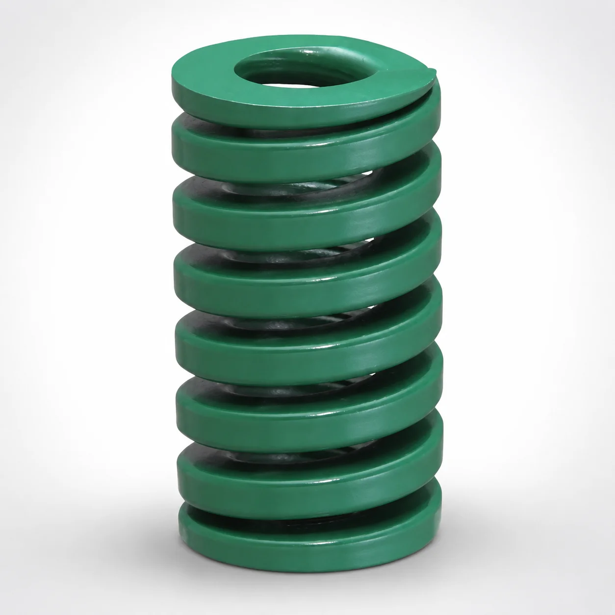
JIS Standard Heavy Duty Die Spring 24% Deflection
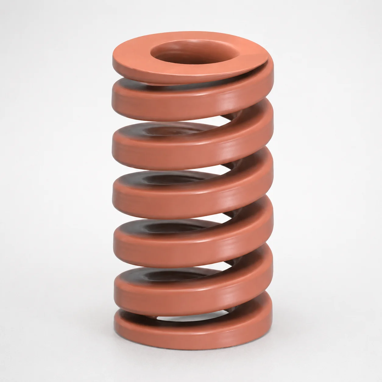
JIS Standard Chrome Silicon Oil-Tempered Wire Heavy Duty Die Spring 20% Deflection
Need Custom Specifications?
Our engineering team can help with custom configurations, material selection, and volume pricing.