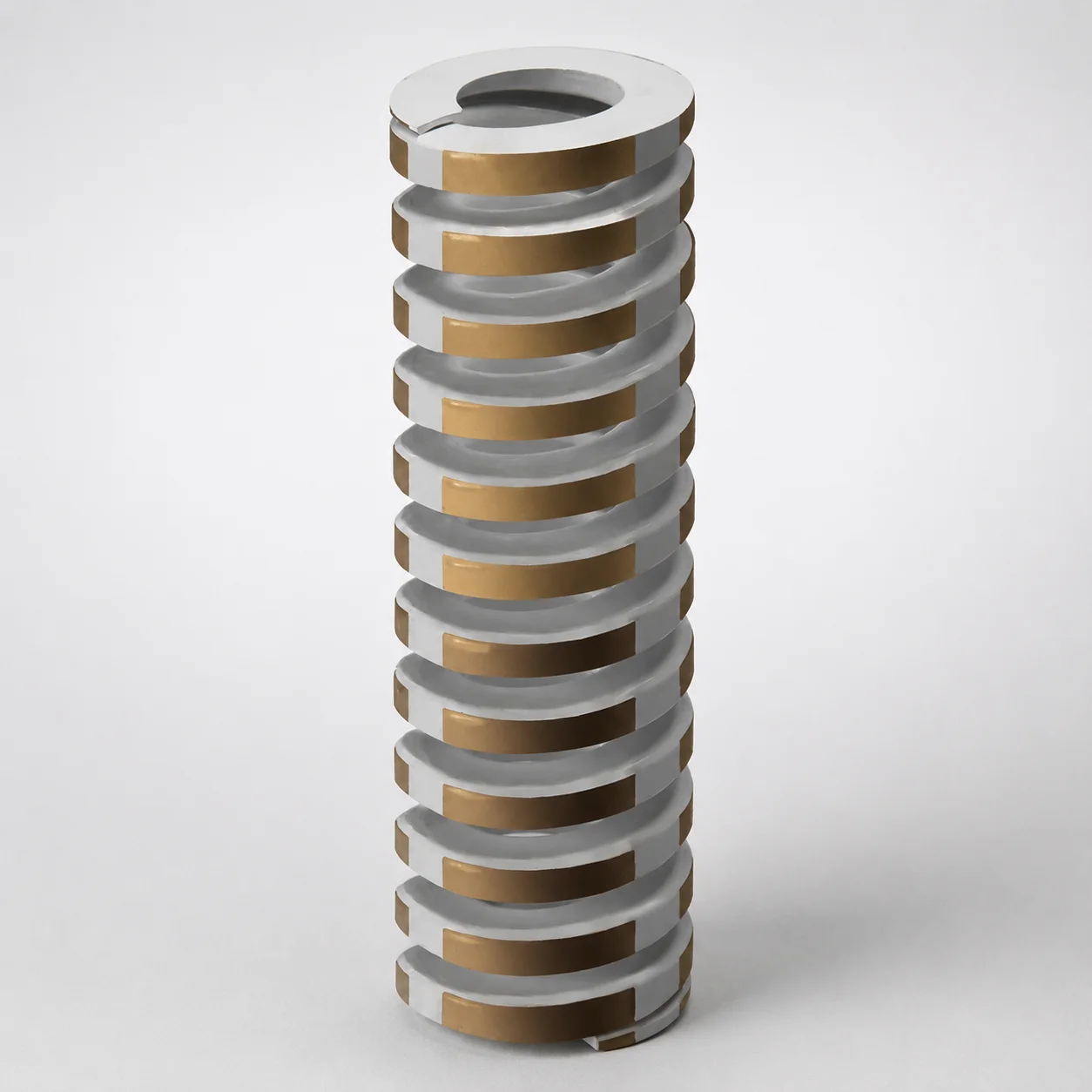
Inch Heavy Duty Die Spring 28% Deflection Chrome Silicon
Heavy Duty Die Spring (28% deflection) (Chrome silicon steel) from Lamina is engineered for demanding die spring applications where reliable load capacity and consistent cycling matter. The inch-form design supports straightforward integration into tooling setups.
- 28% deflection rating for controlled die cushioning under heavy loads
- Chrome silicon steel provides strong resilience and durable spring performance
- Configurable spring dimensions for fit across a wide range of inch-based die layouts
- Built for die casting, forming, and press tooling requiring dependable spring return
Specifications
97 configurations available
| Outer Diameter D (in) | Length L (in) | Max. comp. length (in) | Rod Diameter (in) |
|---|---|---|---|
| 3/4" | 1-1/4" | 0.86" | 3/8" |
| 3/4" | 1" | 0.69" | 3/8" |
| 3/4" | 1-3/4" | 1.19" | 3/8" |
| 3/4" | 1-1/2" | 1.02" | 3/8" |
| 3/4" | 2" | 1.35" | 3/8" |
| 3/4" | 2-1/2" | 1.71" | 3/8" |
| 3/4" | 3" | 2.00" | 3/8" |
| 3/4" | 3-1/2" | 2.33" | 3/8" |
| 3/4" | 4" | 2.67" | 3/8" |
| 3/4" | 4-1/2" | 3.00" | 3/8" |
| 3/4" | 5" | 3.33" | 3/8" |
| 3/4" | 5-1/2" | 3.66" | 3/8" |
| 3/4" | 12" | 7.90" | 3/8" |
| 3/4" | 6" | 3.99" | 3/8" |
| 1" | 1-1/4" | 0.86" | 1/2" |
| 1" | 1" | 0.68" | 1/2" |
| 1" | 1-3/4" | 1.18" | 1/2" |
| 1" | 1-1/2" | 1.03" | 1/2" |
| 1" | 2" | 1.35" | 1/2" |
| 1" | 2-1/2" | 1.68" | 1/2" |
| 1" | 3" | 2.00" | 1/2" |
| 1" | 3-1/2" | 2.33" | 1/2" |
| 1" | 4" | 2.63" | 1/2" |
| 1" | 4-1/2" | 2.94" | 1/2" |
| 1" | 5-1/2" | 3.55" | 1/2" |
| 1" | 5" | 3.26" | 1/2" |
| 1" | 7" | 4.47" | 1/2" |
| 1" | 6" | 3.87" | 1/2" |
| 1" | 12" | 7.80" | 1/2" |
| 1" | 8" | 5.16" | 1/2" |
| 1-1/4" | 1-3/4" | 1.17" | 5/8" |
| 1-1/4" | 1-1/2" | 1.01" | 5/8" |
| 1-1/4" | 2" | 1.34" | 5/8" |
| 1-1/4" | 2-1/2" | 1.68" | 5/8" |
| 1-1/4" | 3" | 2.02" | 5/8" |
| 1-1/4" | 3-1/2" | 2.30" | 5/8" |
| 1-1/4" | 4" | 2.66" | 5/8" |
| 1-1/4" | 4-1/2" | 2.99" | 5/8" |
| 1-1/4" | 5" | 3.30" | 5/8" |
| 1-1/4" | 5-1/2" | 3.62" | 5/8" |
| 1-1/4" | 6" | 3.95" | 5/8" |
| 1-1/4" | 7" | 4.60" | 5/8" |
| 1-1/4" | 8" | 5.25" | 5/8" |
| 1-1/4" | 12" | 7.62" | 5/8" |
| 1-1/4" | 10" | 6.40" | 5/8" |
| 1-1/2" | 2" | 1.34" | 3/4" |
| 1-1/2" | 2-1/2" | 1.68" | 3/4" |
| 1-1/2" | 3" | 1.99" | 3/4" |
| 1-1/2" | 3-1/2" | 2.30" | 3/4" |
| 1-1/2" | 4" | 2.62" | 3/4" |
Product Guide
Application Scenarios+
This die spring variant is used in injection mold and related tooling where the spring stack must deliver stable return force under repeated compression. A common scenario is automotive connector and insert molding, where ejector mechanisms and core/cavity inserts benefit from predictable load at a set deflection level; the 28% deflection rating helps maintain consistent cushioning and recoil during fast cycling.
It is also well suited for metal-forming or die-casting process tooling that shares similar wear and shock loading characteristics with industrial molds. Chrome-silicon spring construction supports long-cycle performance when repeated load spikes occur.
For press and transfer tooling that uses coil spring stacks for die-height compensation, selecting dimensions within the provided inch ranges ensures direct compatibility with existing die layouts. Use the outer diameter and free length to match the available spring pocket space and guide constraints, supporting straightforward integration and controlled compression behavior.
- Use when stable force at the designed deflection is critical for ejector return and die-height compensation.
- Choose within available inch outer diameter (1–5 in) and length (1–12 in) ranges for fit to tooling pockets.
Material & Process Details+
The product uses chrome silicon steel, a spring-grade alloy designed to combine high resilience with improved fatigue resistance for demanding die cycles. Chrome and silicon additions enhance hardenability and help maintain elastic performance after repeated loading.
In typical spring manufacturing, the material is formed and then heat treated to develop spring hardness and elastic recovery, followed by tempering to balance toughness and long-term stress relaxation. Because the provided data does not specify the exact grade or final heat-treatment condition, engineers should verify the delivered hardness and temper state on the material cert for this series.
- Wear resistance: good for cyclic contact and load-bearing service in die tooling.
- Toughness vs. hardness trade-off: higher hardness can increase fatigue performance, while tempering improves toughness to reduce risk from shock loading.
- Comparison: chrome-silicon spring steel generally outperforms plain-carbon spring steels for fatigue stability in long-cycle tooling, while stainless spring options (if offered) typically trade cost and elastic fatigue behavior for corrosion resistance.
Sizing & Selection Guide+
Correct selection starts with matching the spring to the die pocket geometry and the mechanism’s required compression. Use the available Outer Diameter D (1–5 in) to fit the spring seat and avoid binding in the guide path.
Next, choose the free length L (1–12 in) so that, in the assembled condition, the spring can compress to the design working range without bottoming out. The series specifies a Max. comp. length of 0.62–7.9 in; ensure your intended compressed height is greater than (or equal to, per your tolerance strategy) this maximum allowable value.
- Check rod diameter (1–11 in) compatibility with any inner guide/mandrel features. If your spring is used in a constrained stack, rod diameter must clear the spring’s intended working envelope.
- For stack applications, confirm total deflection (target load condition) aligns with the 28% deflection design level.
Because tolerance values are not provided, specify the spring and mating components with appropriate fit allowances based on your die design drawings and available space for alignment.
Frequently Asked Questions
How do I verify that the spring can compress without bottoming for my die-height range?+
Which dimension should control fit in the spring pocket: outer diameter D or free length L?+
Does the stated 28% deflection rating affect how I model ejector return force in tooling?+
What should I confirm about material and heat treatment when selecting chrome silicon die springs for long-cycle molds?+
How do I ensure the spring works with guided mechanisms that specify a rod diameter?+
Related Products
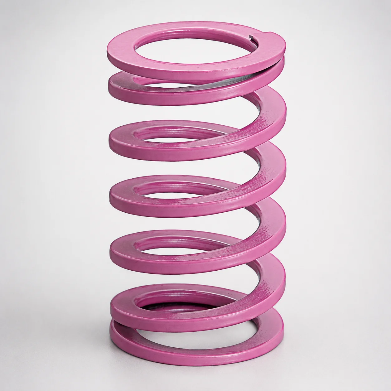
JIS Standard Chrome Silicon Medium Duty Die Spring 60% Deflection
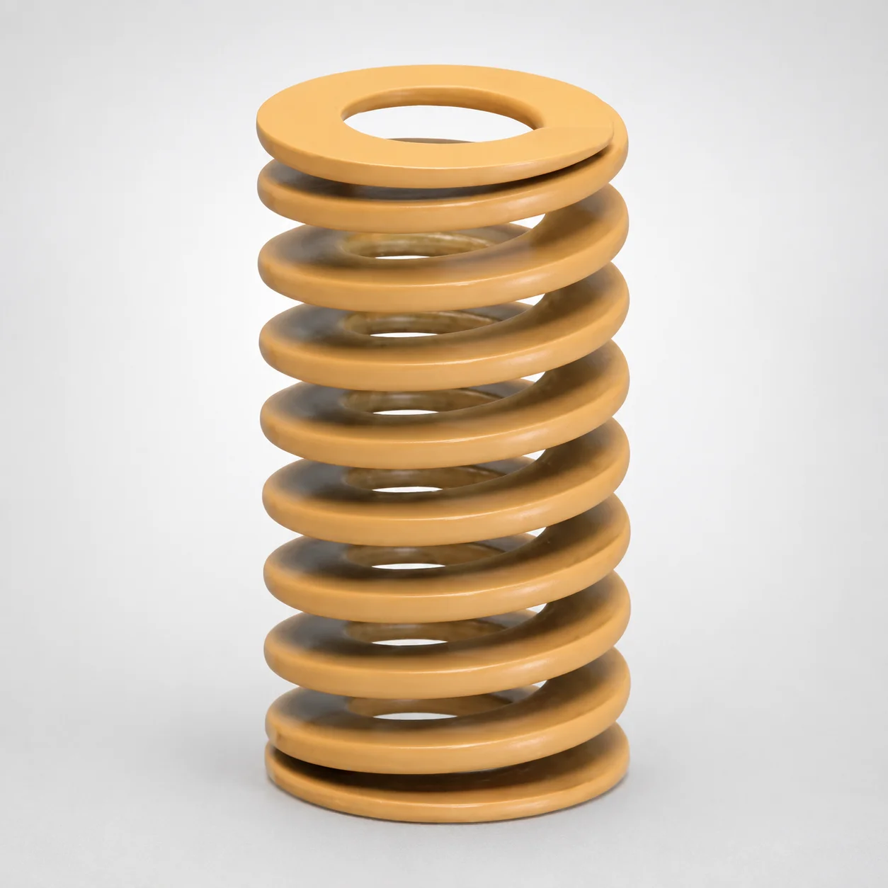
JIS Standard Chrome Silicon Medium Duty Die Spring - 50% Deflection
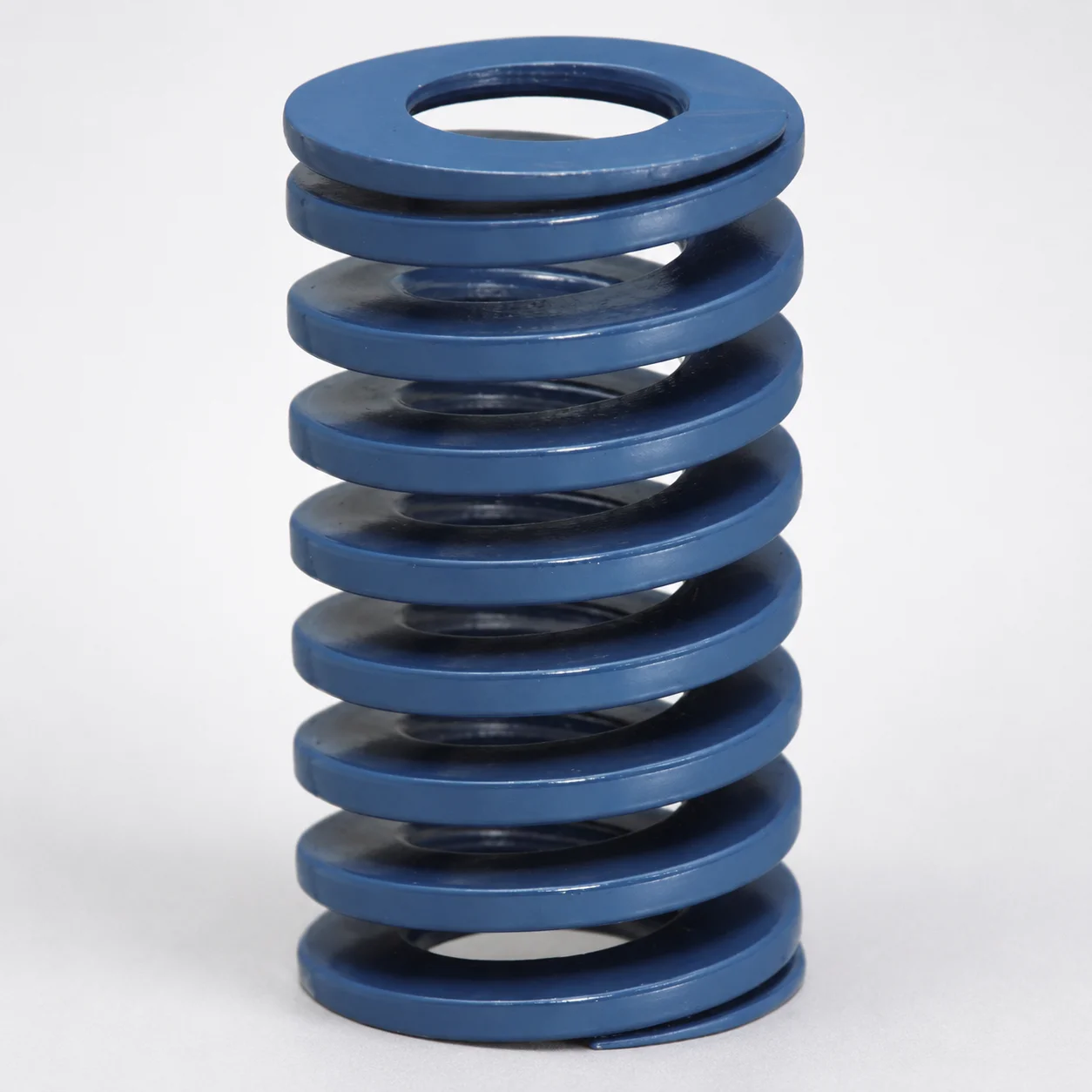
JIS Standard Chrome Silicon Steel Medium Duty Die Spring - 40% Deflection
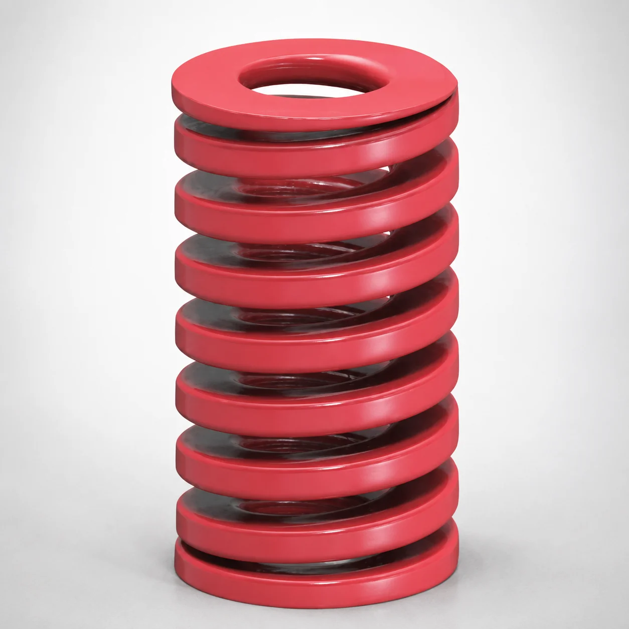
JIS Standard Medium Duty Die Spring 32% Deflection Chrome Silicon Coil Springs
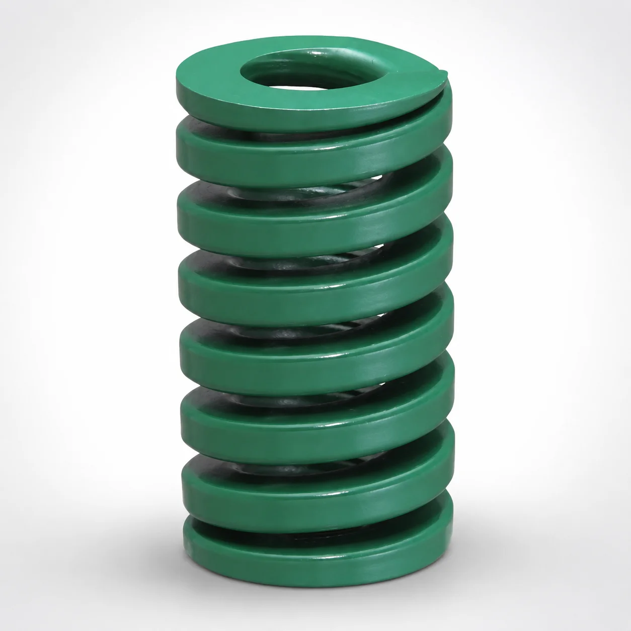
JIS Standard Heavy Duty Die Spring 24% Deflection
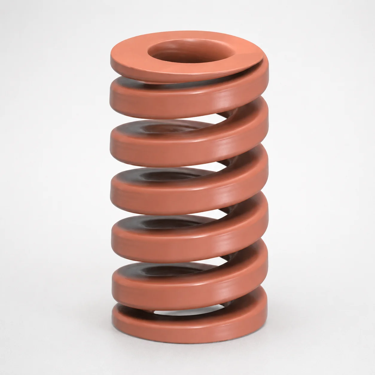
JIS Standard Chrome Silicon Oil-Tempered Wire Heavy Duty Die Spring 20% Deflection
Need Custom Specifications?
Our engineering team can help with custom configurations, material selection, and volume pricing.