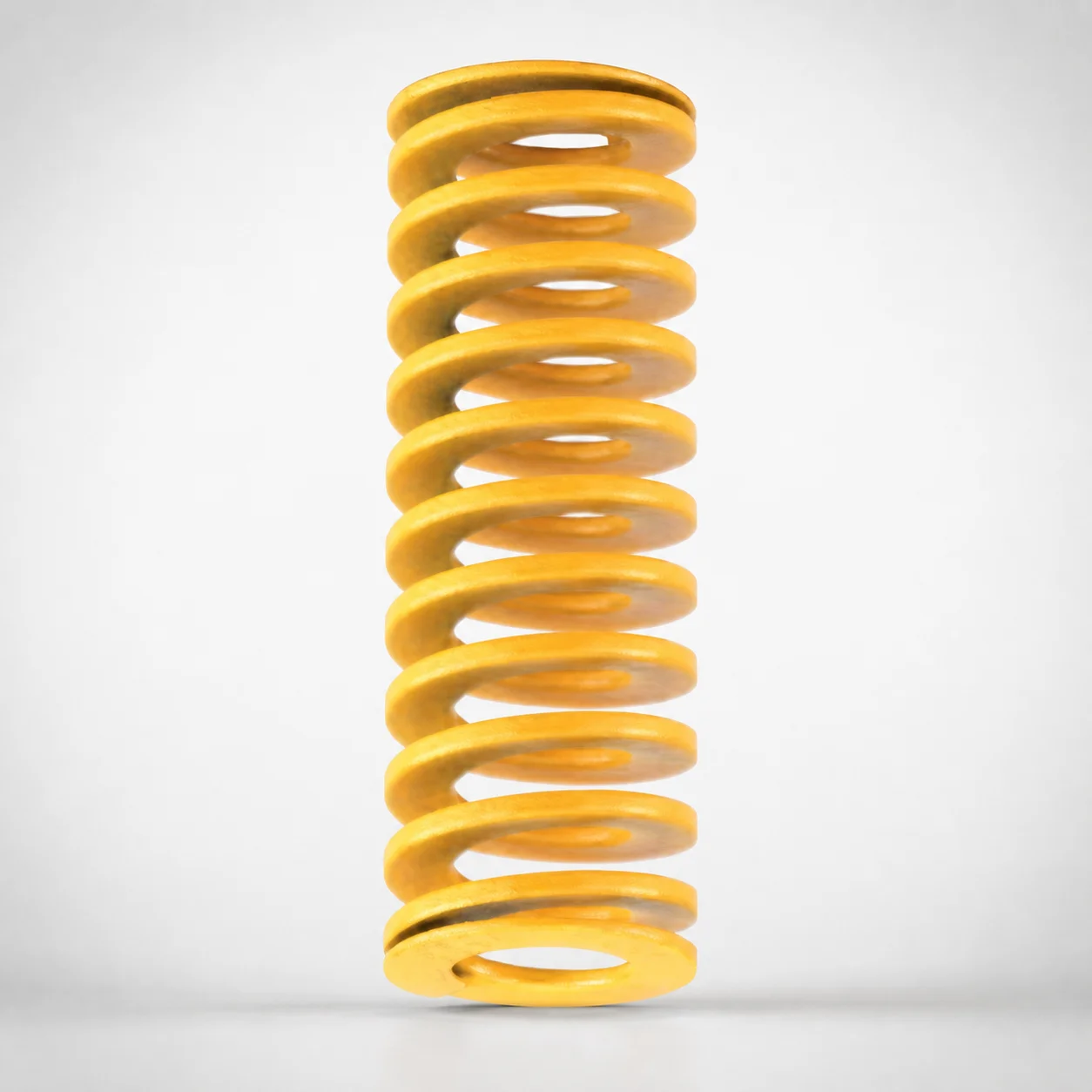
JIS Standard Chrome Silicon Extra Light Duty Die Spring - 50% Deflection
Extra Light Duty Die Spring - 50% Deflection from DANLY IEM (chrome silicon) is engineered for dependable support and flexibility, keeping consistent performance as loads change in die applications.
- 50:50 allowable deflection ratio improves support response under varying load conditions
- Chrome silicon spring steel with corrosion-resistant performance for long service life
- Designed for die use requiring compact spring behavior across a broad size range
- Built to JIS specifications for reliable compatibility in Japanese-standard toolings
Specifications
201 configurations available
| type | Outer Diameter D (mm) | Length L (mm) | d (Inner diameter) (mm) |
|---|---|---|---|
| - | 10 | 20 | 5 |
| - | 10 | 25 | 5 |
| - | 10 | 30 | 5 |
| - | 10 | 35 | 5 |
| - | 10 | 40 | 5 |
| - | 10 | 45 | 5 |
| - | 10 | 50 | 5 |
| - | 10 | 55 | 5 |
| - | 10 | 60 | 5 |
| - | 10 | 65 | 5 |
| - | 10 | 70 | 5 |
| - | 10 | 75 | 5 |
| - | 10 | 80 | 5 |
| - | 12 | 20 | 6 |
| - | 12 | 25 | 6 |
| - | 12 | 30 | 6 |
| - | 12 | 35 | 6 |
| - | 12 | 40 | 6 |
| - | 12 | 45 | 6 |
| - | 12 | 50 | 6 |
| - | 12 | 55 | 6 |
| - | 12 | 60 | 6 |
| - | 12 | 65 | 6 |
| - | 12 | 70 | 6 |
| - | 12 | 75 | 6 |
| - | 12 | 80 | 6 |
| - | 14 | 25 | 7 |
| - | 14 | 30 | 7 |
| - | 14 | 35 | 7 |
| - | 14 | 40 | 7 |
| - | 14 | 45 | 7 |
| - | 14 | 50 | 7 |
| - | 14 | 55 | 7 |
| - | 14 | 60 | 7 |
| - | 14 | 65 | 7 |
| - | 14 | 70 | 7 |
| - | 14 | 75 | 7 |
| - | 14 | 80 | 7 |
| - | 14 | 90 | 7 |
| - | 16 | 100 | 8 |
| - | 16 | 25 | 8 |
| - | 16 | 30 | 8 |
| - | 16 | 35 | 8 |
| - | 16 | 40 | 8 |
| - | 16 | 45 | 8 |
| - | 16 | 50 | 8 |
| - | 16 | 55 | 8 |
| - | 16 | 60 | 8 |
| - | 16 | 65 | 8 |
| - | 16 | 70 | 8 |
Product Guide
Application Scenarios+
This JIS-compliant die spring is used in injection and forming mold tooling wherever compact, consistent load support is needed and the working load varies during cycling. The 50% deflection behavior helps maintain stable force response as the die height or part geometry changes, which is particularly valuable in precision multi-cavity and wear-compensated stations.
- Automotive and appliance stamping/die sets: supports stripper plates, ejector-related die components, or light spring stacks that must retract reliably without excessive travel.
- Industrial connector and small-part inserts: assists in maintaining positional repeatability in die inserts where spring working space is limited by cavity layout.
- Progressive die tooling: smooths load fluctuations across successive forming stages, reducing the risk of inconsistent contact pressure.
Because this variant uses chrome silicon spring steel and is built to JIS standards, it is suited for tooling environments that require predictable deflection characteristics and compatibility with Japanese-standard die spring sizing.
Material & Process Details+
Made from chrome silicon spring steel, this die spring is designed for elastic performance under repeated cycling. Chrome silicon steels are chosen for their balance of wear/abrasion resistance and toughness, with improved resistance to surface degradation compared with lower-alloy spring materials.
- Heat treatment (typical spring practice): pre-hardened and then quenched/tempered to develop spring hardness and stable elastic properties before forming into the final coil geometry.
- Hardness and trade-offs: higher hardness increases spring wear resistance and dimensional stability, while excessive hardness can reduce toughness; chrome silicon grade tuning targets durable cyclic life.
- Why this steel for tooling: good fatigue behavior supports consistent force over deflection, which matches the product’s 50% deflection use intent.
If you compare alternatives, most non-chrome spring steels may offer lower corrosion resistance, while higher-alloy tool steels can improve wear but may require more demanding processing to retain spring elasticity.
Sizing & Selection Guide+
To select the correct die spring, match its coil geometry to the available space and the required working stroke in the mold. This series provides outer diameter (D) = 10–60 mm, length (L) = 20–300 mm, and inner diameter (d) = 5–33 mm.
- Check clearance around the spring: ensure your mounting envelope can accommodate D and that the surrounding components won’t interfere during full deflection.
- Verify working height: choose L so the spring can compress to the intended working position without reaching coil bind.
- Confirm the shaft/pass-through fit: use d to confirm compatibility with guide posts or related features.
Because exact tolerances are not specified in the provided data, confirm fit using your die spring housing/guide design clearances and your target compression level. When multiple options exist within D/L/d ranges, prefer the size that maintains the most stable alignment to reduce side-loading and frictional wear.
Frequently Asked Questions
How do I size this JIS die spring for a 50% deflection working stroke in a die assembly?+
What outer diameter (D) and inner diameter (d) combinations are available for mounting and guide compatibility?+
Is this die spring suitable for environments where corrosion or moisture exposure affects die life?+
Do I need to worry about JIS compatibility when replacing an existing die spring in Japanese-standard tooling?+
How should I prevent side-loading and premature wear with a die spring of this size range?+
Related Products
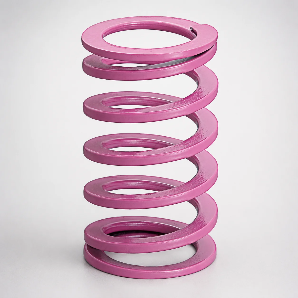
JIS Standard Chrome Silicon Medium Duty Die Spring 60% Deflection
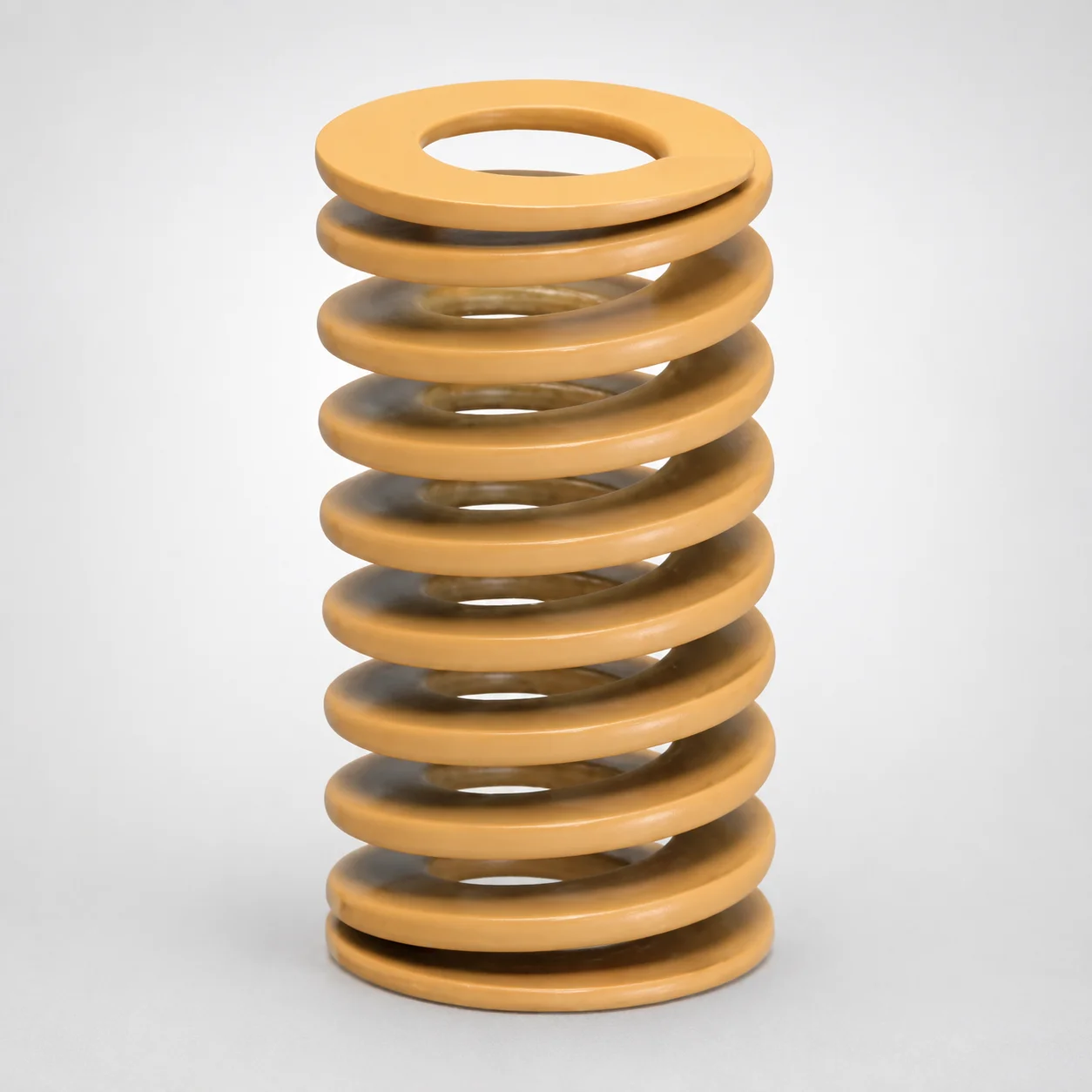
JIS Standard Chrome Silicon Medium Duty Die Spring - 50% Deflection
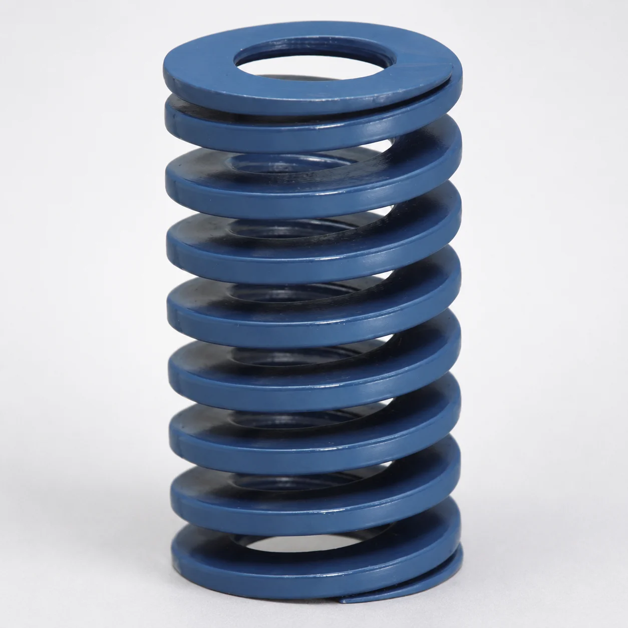
JIS Standard Chrome Silicon Steel Medium Duty Die Spring - 40% Deflection
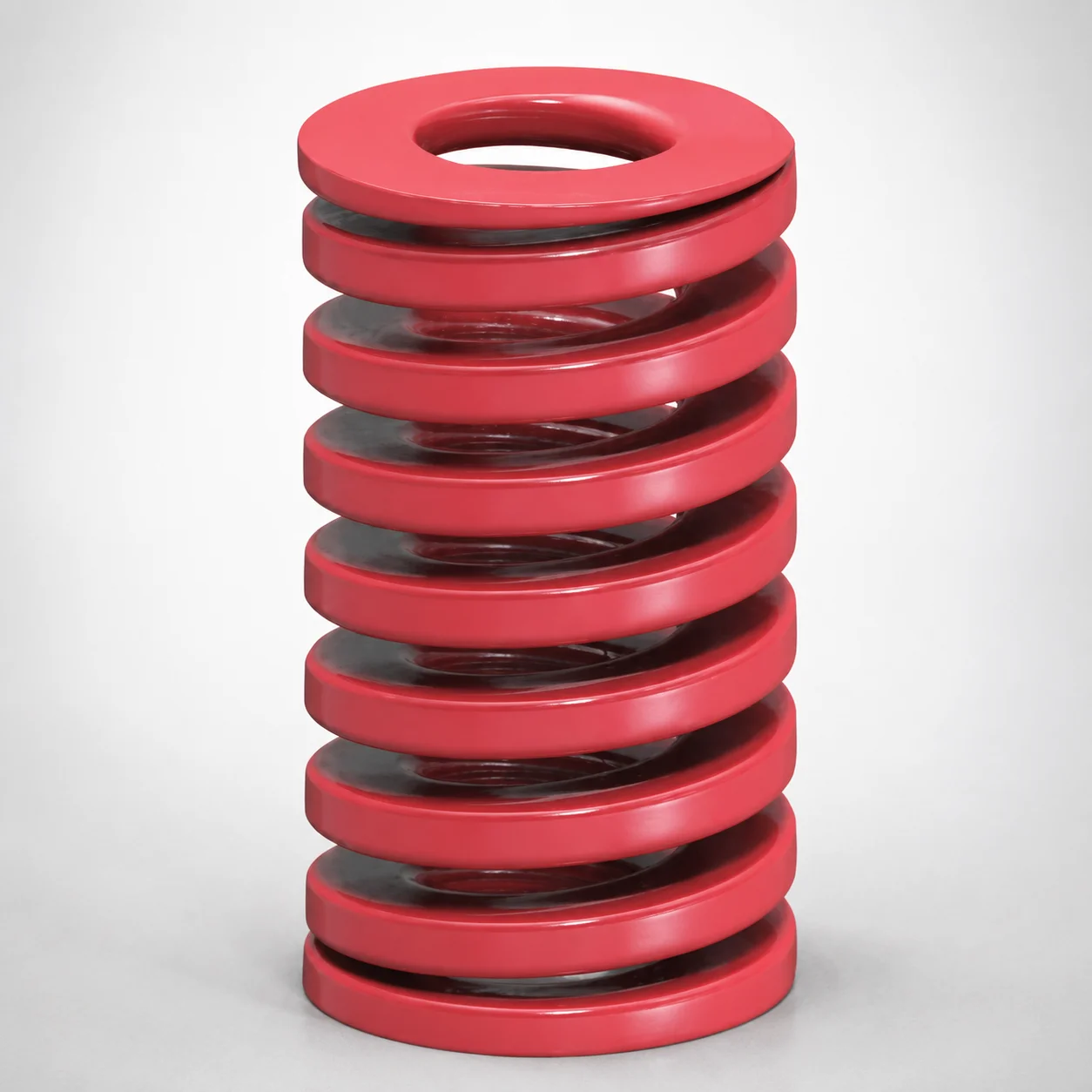
JIS Standard Medium Duty Die Spring 32% Deflection Chrome Silicon Coil Springs
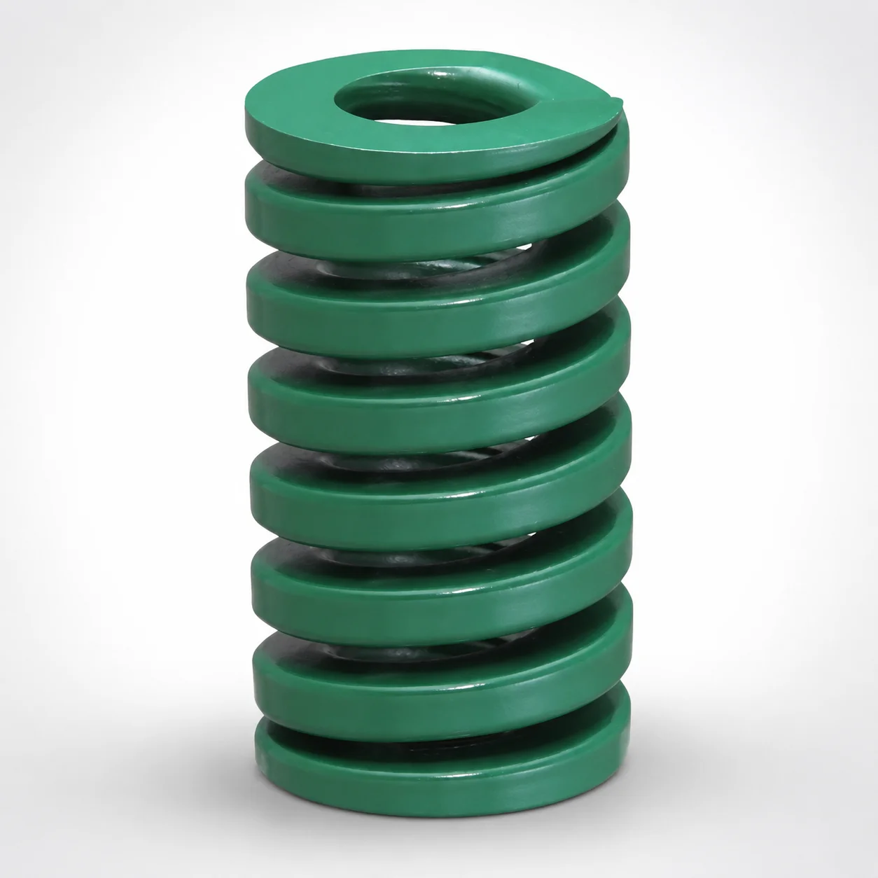
JIS Standard Heavy Duty Die Spring 24% Deflection
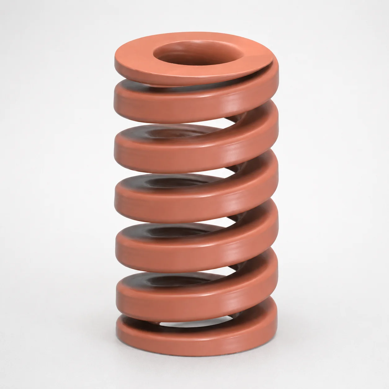
JIS Standard Chrome Silicon Oil-Tempered Wire Heavy Duty Die Spring 20% Deflection
Need Custom Specifications?
Our engineering team can help with custom configurations, material selection, and volume pricing.