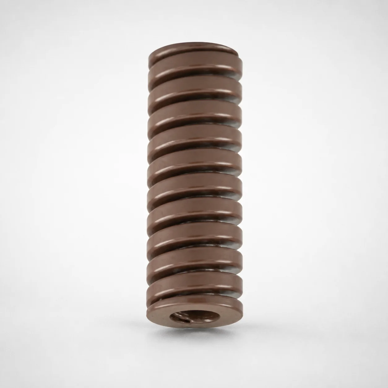
JIS Standard Chrome Silicon Extra Heavy Duty Die Spring - 20% Deflection
Extra Heavy Duty Die Spring - 20% Deflection (Chrome Silicon) in a JIS configuration is engineered for heavy die load support, helping maintain stable operation under varying tooling demands. The coil design efficiently absorbs shock and reduces vibration to protect sensitive systems.
- Extra-heavy duty construction for consistent support under high loads
- Chrome silicon spring steel for durable resilience and vibration damping
- Built to accommodate assembly variations with reliable performance over time
- Suitable for industrial die applications requiring dependable return force
Specifications
201 configurations available
| type | Outer Diameter D (mm) | Length L (mm) | d (Inner diameter) (mm) |
|---|---|---|---|
| - | 10 | 20 | 5 |
| - | 10 | 25 | 5 |
| - | 10 | 30 | 5 |
| - | 10 | 35 | 5 |
| - | 10 | 40 | 5 |
| - | 10 | 45 | 5 |
| - | 10 | 50 | 5 |
| - | 10 | 55 | 5 |
| - | 10 | 60 | 5 |
| - | 10 | 65 | 5 |
| - | 10 | 70 | 5 |
| - | 10 | 75 | 5 |
| - | 10 | 80 | 5 |
| - | 12 | 20 | 6 |
| - | 12 | 25 | 6 |
| - | 12 | 30 | 6 |
| - | 12 | 35 | 6 |
| - | 12 | 40 | 6 |
| - | 12 | 45 | 6 |
| - | 12 | 50 | 6 |
| - | 12 | 55 | 6 |
| - | 12 | 60 | 6 |
| - | 12 | 65 | 6 |
| - | 12 | 70 | 6 |
| - | 12 | 75 | 6 |
| - | 12 | 80 | 6 |
| - | 14 | 25 | 7 |
| - | 14 | 30 | 7 |
| - | 14 | 35 | 7 |
| - | 14 | 40 | 7 |
| - | 14 | 45 | 7 |
| - | 14 | 50 | 7 |
| - | 14 | 55 | 7 |
| - | 14 | 60 | 7 |
| - | 14 | 65 | 7 |
| - | 14 | 70 | 7 |
| - | 14 | 75 | 7 |
| - | 14 | 80 | 7 |
| - | 14 | 90 | 7 |
| - | 16 | 100 | 8 |
| - | 16 | 25 | 8 |
| - | 16 | 30 | 8 |
| - | 16 | 35 | 8 |
| - | 16 | 40 | 8 |
| - | 16 | 45 | 8 |
| - | 16 | 50 | 8 |
| - | 16 | 55 | 8 |
| - | 16 | 60 | 8 |
| - | 16 | 65 | 8 |
| - | 16 | 70 | 8 |
Product Guide
Application Scenarios+
This JIS-configured die spring variant is used in precision injection mold tooling where the die cavity/core assembly must return reliably after opening and closing cycles. Its 20% deflection rating helps absorb impact energy from heavy die loads, reducing vibration that can disturb alignment in high-cycle molds.
- Automotive part forming & large-insert molds: Integrate in stripper plate or die-set return systems to maintain consistent return force when stamping blocks, hot-runner nozzles, or large cavity inserts create higher loads.
- Industrial housings and thick-wall components: Use in molds that experience repeated opening shock; the spring’s chrome-silicon resilience supports stable behavior across varying tooling demands.
- Multi-slide or auxiliary-actuated die stations: Suitable where assembly variations require dependable shock absorption to protect adjacent mechanisms and maintain repeatable stroke recovery.
The chrome-silicon material and heavy-duty construction make it a strong match for applications needing dependable return force under intermittent load spikes.
Material & Process Details+
This spring is made from chrome silicon spring steel, selected for its high elastic resilience and good resistance to fatigue-driven relaxation in cyclic tooling conditions. In practice, chrome-silicon grades are commonly supplied in a heat-treated state (typically quenched and tempered) to balance strength and toughness.
- Heat treatment (typical for chrome-silicon die springs): quenched & tempered to achieve reliable spring temper and stable modulus for repeated deflection.
- Hardness & performance: chrome-silicon steels generally provide high hardness with strong wear/fatigue resistance; the exact HRC level is dependent on the temper cycle used by the supplier.
- Trade-offs: increasing hardness improves fatigue life and resistance to set, while reduced toughness can lower impact tolerance—this spring is built as an extra heavy duty option to preserve performance under shock loads.
If compared against lower-alloy steels, chrome-silicon typically offers better fatigue resistance and stress-relaxation stability for die return use, especially under higher cycle loads.
Sizing & Selection Guide+
To select the correct die spring, match the spring outer diameter (D), inner diameter (d), and free length (L) to your mold’s guide, seat, and available space. This product series covers D = 10–60 mm, d = 5–30 mm, and L = 20–300 mm.
- Check packaging/space: Ensure the installed length and surrounding clearances fit within the return assembly envelope for L.
- Confirm guide compatibility: Verify that the d aligns with the guide rod/center post and that D does not interfere with the spring pocket, cap, or neighboring components.
- Deflection suitability: This variant is rated for 20% deflection, so the chosen spring should be sized such that operating stroke stays within the intended deflection window to maintain return force stability.
Account for fit tolerance between spring OD and pocket ID, and between d and the center hardware, to prevent binding and ensure smooth cycling.
Frequently Asked Questions
What does the “20% deflection” rating mean for die return force in injection mold tooling?+
The spring is specified as an extra heavy duty die spring with a 20% deflection characteristic. In die-set applications, this means its force behavior is intended to be evaluated and selected around that deflection region to maintain stable return force during cycling.
When designing the mold, ensure the working stroke does not exceed the intended deflection window for consistent performance.
How do I choose the correct outer diameter D when selecting this JIS die spring for a spring pocket?+
Use the available outer diameter D range of 10–60 mm to match your spring pocket geometry and clearance. The spring OD should fit without interference while allowing enough tolerance for assembly and thermal expansion.
Confirm the pocket ID/seat geometry and account for manufacturing tolerances to prevent rubbing or binding during deflection.
How should I select inner diameter d for alignment with the mold’s guide post or center rod?+
This series provides inner diameter d from 5–30 mm. Select the d that gives proper clearance over the center rod/post and ensures concentric movement through the guide assembly.
If the d tolerance is too tight, the spring can bind under load; too loose can increase misalignment and uneven wear in the pocket.
What length L range is available, and how do I relate it to the mold’s available stack height?+
Available length L is 20–300 mm. Choose the free length that fits the available stack height in your return assembly while still achieving the required deflection under the expected die load.
Also check for minimum clearance at maximum compression to avoid coil bind.
Why is chrome-silicon spring steel appropriate for heavy die load applications compared with other spring steels?+
Chrome-silicon spring steel is selected for strong cyclic resilience and fatigue resistance, supporting reliable behavior under repeated die-set opening/closing impacts. It is typically supplied after heat treatment (commonly quenched and tempered) to create a stable spring temper.
This helps resist loss of force and maintain dependable return function under heavy loads.
Related Products
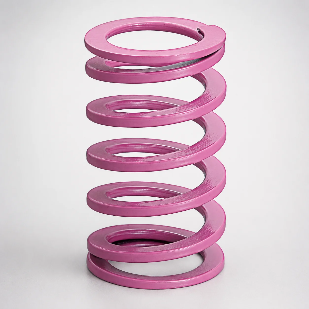
JIS Standard Chrome Silicon Medium Duty Die Spring 60% Deflection
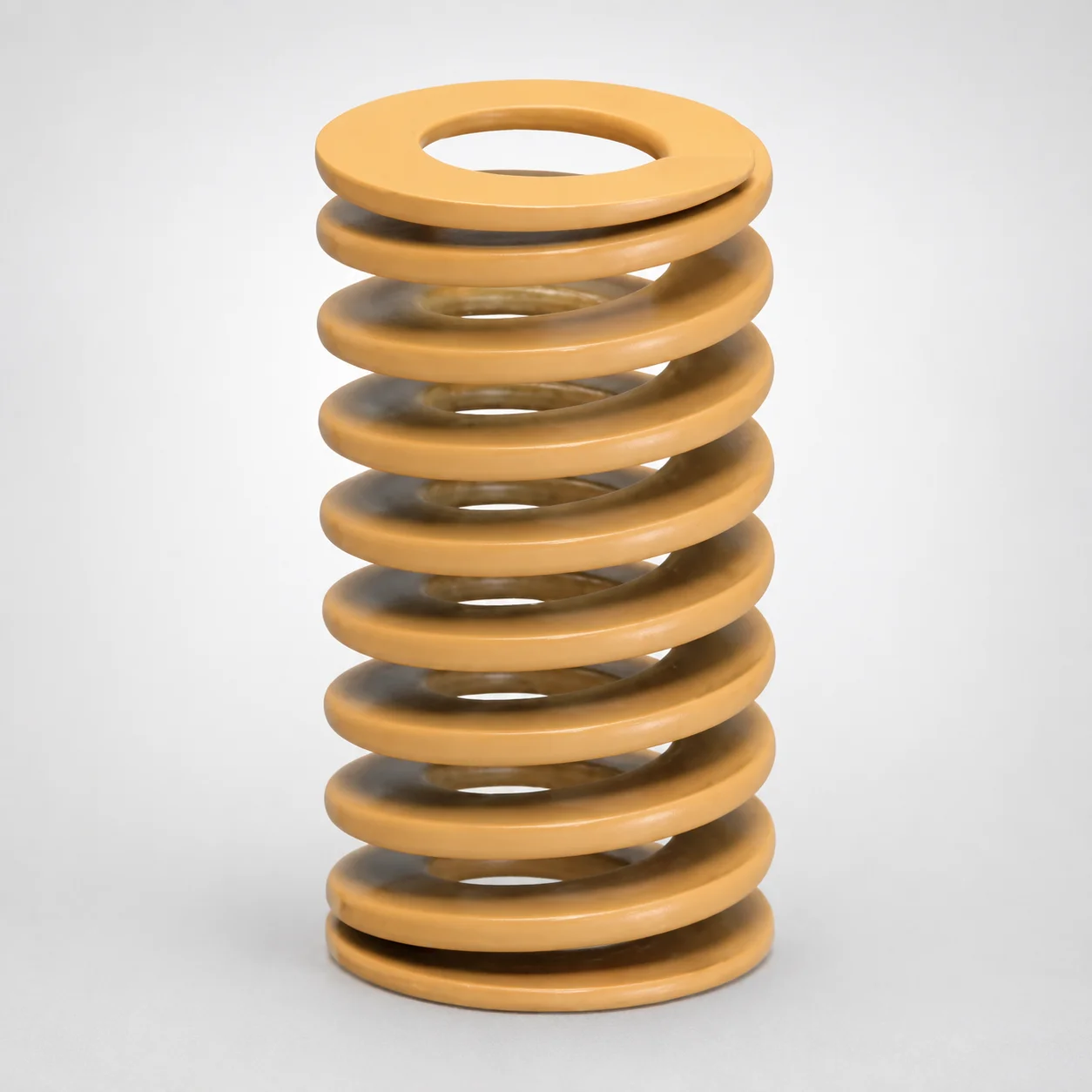
JIS Standard Chrome Silicon Medium Duty Die Spring - 50% Deflection
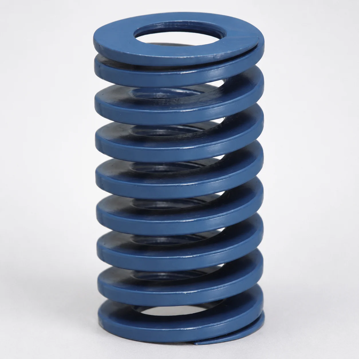
JIS Standard Chrome Silicon Steel Medium Duty Die Spring - 40% Deflection
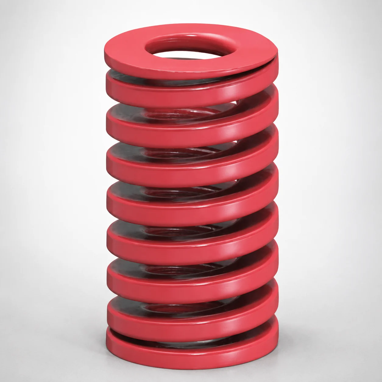
JIS Standard Medium Duty Die Spring 32% Deflection Chrome Silicon Coil Springs
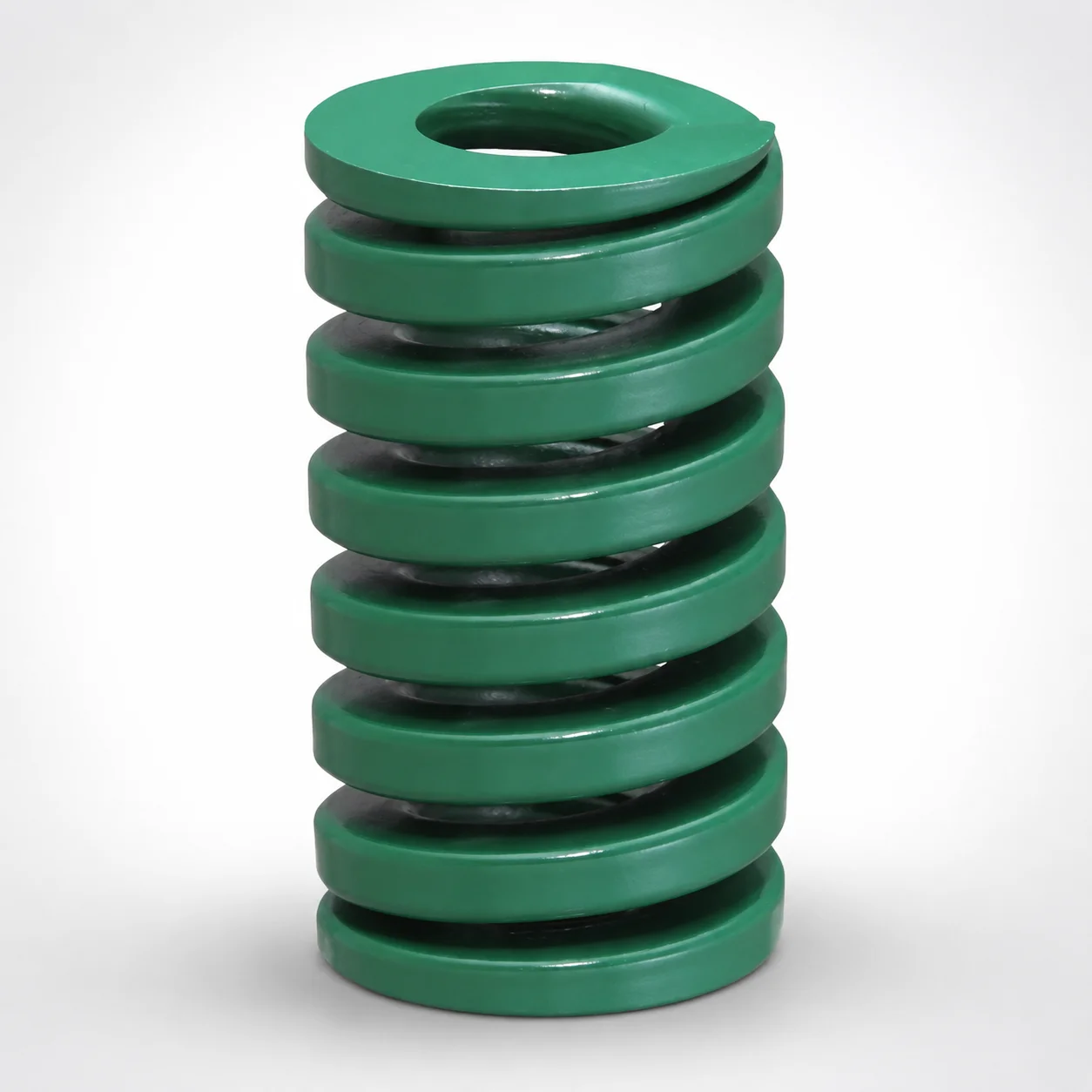
JIS Standard Heavy Duty Die Spring 24% Deflection
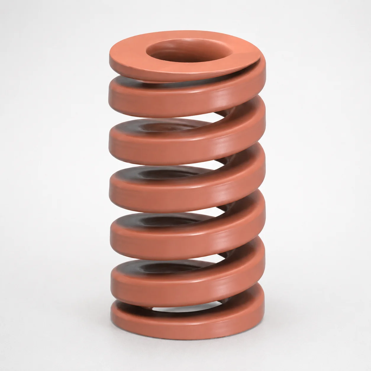
JIS Standard Chrome Silicon Oil-Tempered Wire Heavy Duty Die Spring 20% Deflection
Need Custom Specifications?
Our engineering team can help with custom configurations, material selection, and volume pricing.