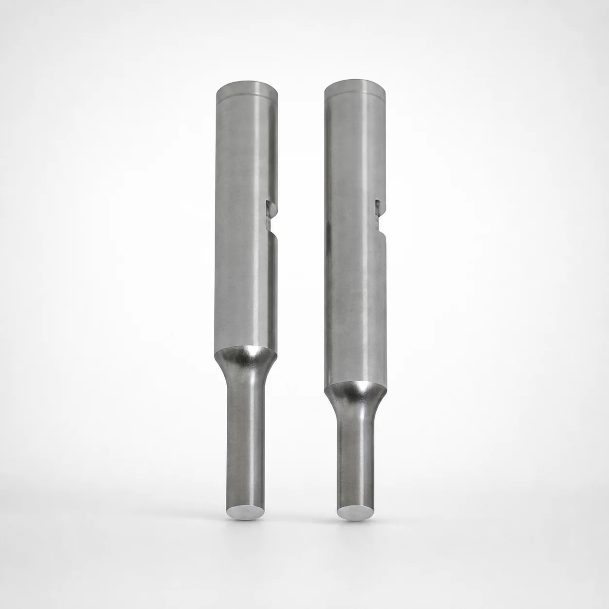
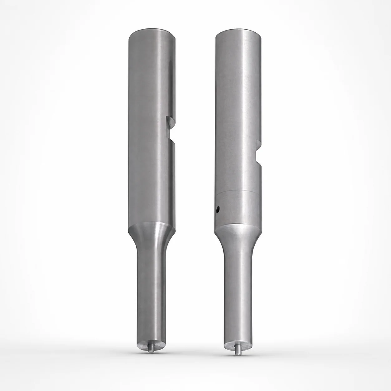
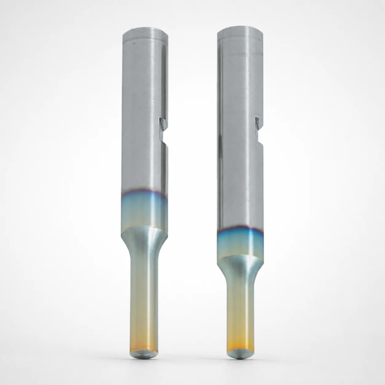
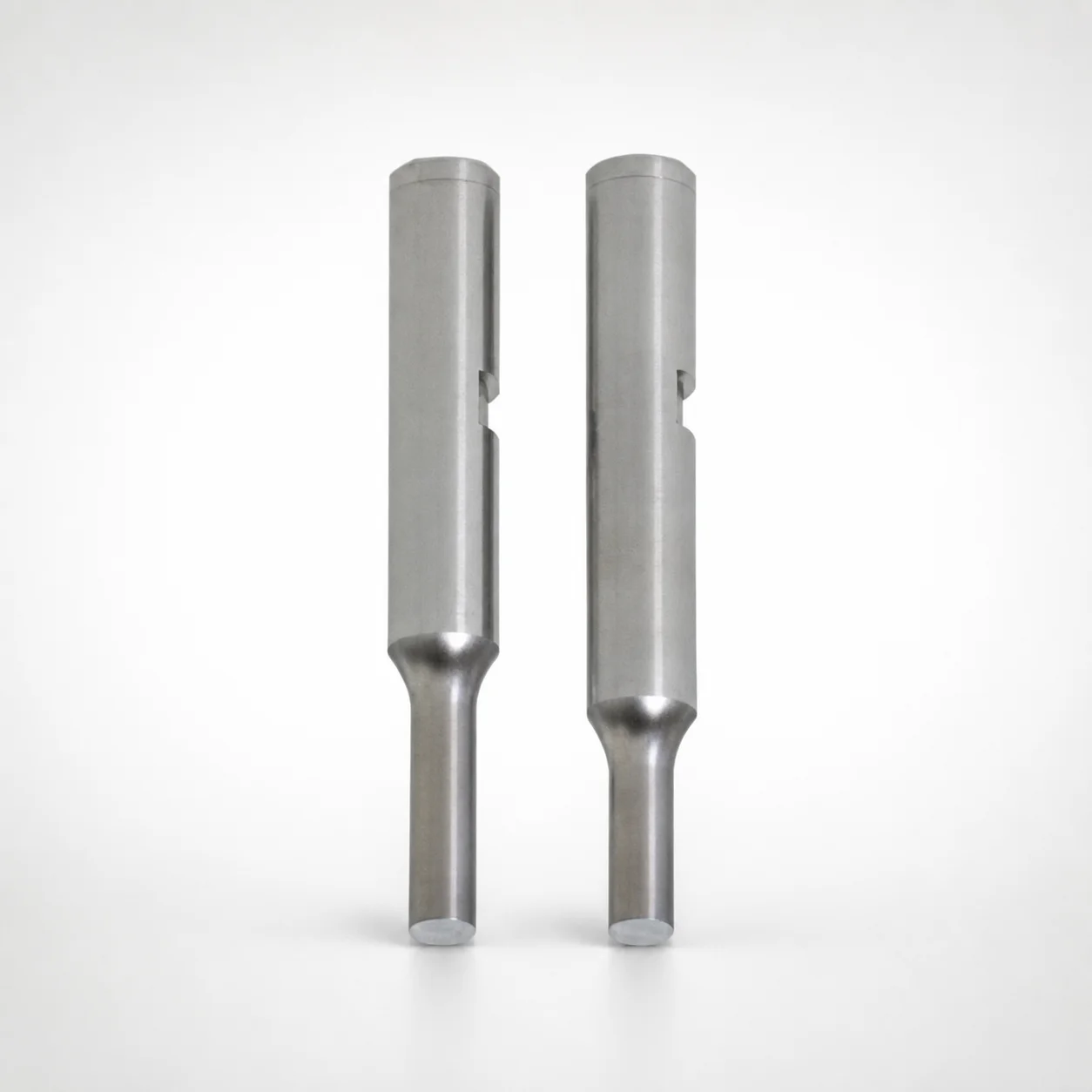
RP Coated Punches with Key Grooves
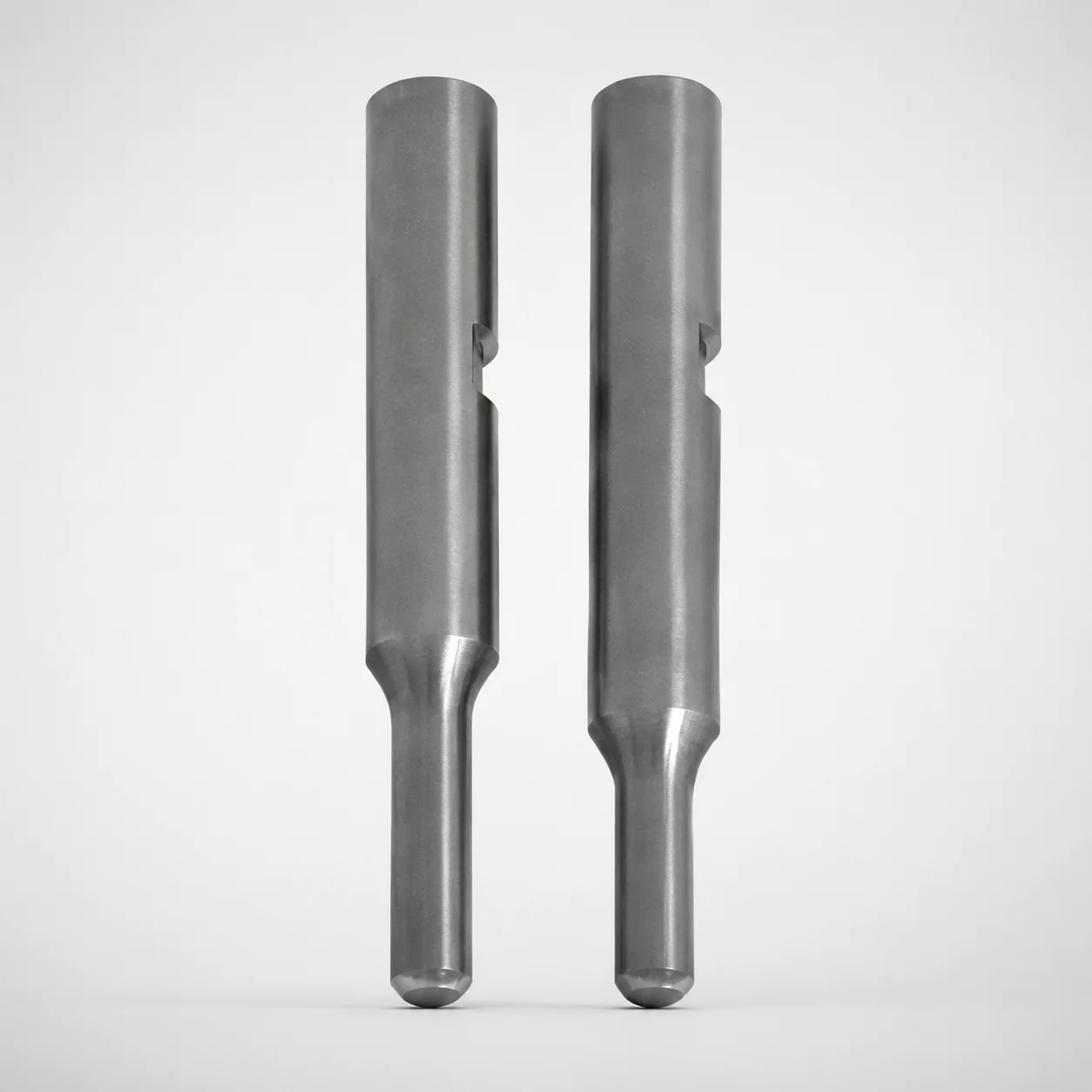
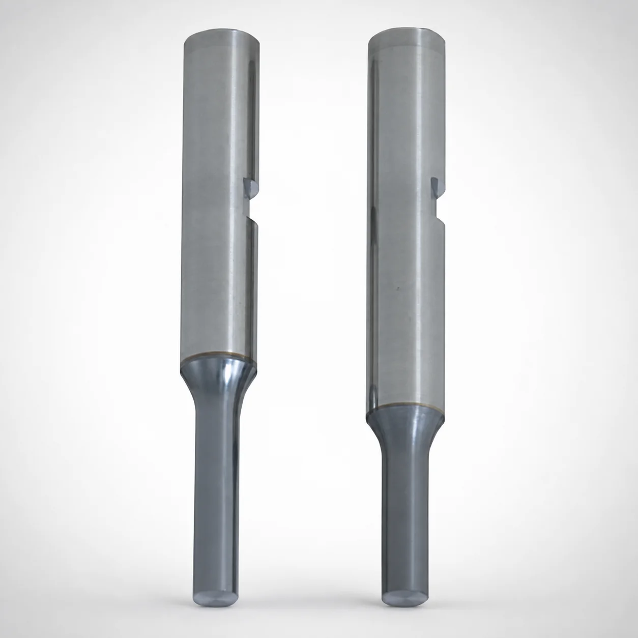
RP coated punches with key grooves use an Al-Cr based coating plus Alpha treatment to strengthen coating adhesion and wear resistance under repeated punching loads.
- Al-Cr based RP coating designed for high hardness and heat resistance during production
- Alpha treatment improves film adhesion to the substrate for better coating durability
- Extends punch life even where traditional coatings show limited durability
- Helps reduce mold maintenance downtime and overall maintenance costs for punch tools
Specifications
3552 configurations available
| Tip shape | Material | Shank diameter D tolerance | B (Tip length) | D (Shank diameter) (mm) | P (Tip dimension) (mm) | L (L dimension) (mm) | LC (Full length alteration) (mm) | LCT (Head thickness tolerance change + total length alteration) (mm) | PC (Tip dimension alteration) (mm) | R (Tip corner R) (mm) | T (Key groove position) (mm) | W (Tip dimension) (mm) | WC (Tip dimension alteration) (mm) | type |
|---|---|---|---|---|---|---|---|---|---|---|---|---|---|---|
| A | Powdered high-speed steel | +0.005/0 | L | 3 | 1 ~ 2.99 | 50 ~ 80 | - | - | - | - | 5.1 ~ 80 | - | - | - |
| A | Powdered high-speed steel | +0.005/0 | L | 3 | - | 50 ~ 80 | - | - | 0.5 ~ 0.99 | - | 5.1 ~ 80 | - | - | - |
| A | Powdered high-speed steel | +0.005/0 | L | 3 | 1 ~ 2.99 | - | 27 ~ 79.9 | - | - | - | 5.1 ~ 80 | - | - | - |
| A | Powdered high-speed steel | +0.005/0 | L | 3 | - | - | 27 ~ 79.9 | - | 0.5 ~ 0.99 | - | 5.1 ~ 80 | - | - | - |
| A | Powdered high-speed steel | +0.005/0 | L | 3 | 1 ~ 2.99 | - | - | 27 ~ 79.9 | - | - | 5.1 ~ 80 | - | - | - |
| A | Powdered high-speed steel | +0.005/0 | L | 3 | - | - | - | 27 ~ 79.9 | 0.5 ~ 0.99 | - | 5.1 ~ 80 | - | - | - |
| A | Powdered high-speed steel | +0.005/0 | L | 4 | 1 ~ 3.99 | 50 ~ 80 | - | - | - | - | 5.1 ~ 80 | - | - | - |
| A | Powdered high-speed steel | +0.005/0 | L | 4 | - | 50 ~ 80 | - | - | 0.5 ~ 0.99 | - | 5.1 ~ 80 | - | - | - |
| A | Powdered high-speed steel | +0.005/0 | L | 4 | 1 ~ 3.99 | - | 27 ~ 79.9 | - | - | - | 5.1 ~ 80 | - | - | - |
| A | Powdered high-speed steel | +0.005/0 | L | 4 | - | - | 27 ~ 79.9 | - | 0.5 ~ 0.99 | - | 5.1 ~ 80 | - | - | - |
| A | Powdered high-speed steel | +0.005/0 | L | 4 | 1 ~ 3.99 | - | - | 27 ~ 79.9 | - | - | 5.1 ~ 80 | - | - | - |
| A | Powdered high-speed steel | +0.005/0 | L | 4 | - | - | - | 27 ~ 79.9 | 0.5 ~ 0.99 | - | 5.1 ~ 80 | - | - | - |
| A | Powdered high-speed steel | +0.005/0 | L | 5 | 2 ~ 4.99 | 50 ~ 80 | - | - | - | - | 5.1 ~ 80 | - | - | - |
| A | Powdered high-speed steel | +0.005/0 | L | 5 | - | 50 ~ 80 | - | - | 1 ~ 1.99 | - | 5.1 ~ 80 | - | - | - |
| A | Powdered high-speed steel | +0.005/0 | L | 5 | 2 ~ 4.99 | - | 27 ~ 79.9 | - | - | - | 5.1 ~ 80 | - | - | - |
| A | Powdered high-speed steel | +0.005/0 | L | 5 | - | - | 27 ~ 79.9 | - | 1 ~ 1.99 | - | 5.1 ~ 80 | - | - | - |
| A | Powdered high-speed steel | +0.005/0 | L | 5 | 2 ~ 4.99 | - | - | 27 ~ 79.9 | - | - | 5.1 ~ 80 | - | - | - |
| A | Powdered high-speed steel | +0.005/0 | L | 5 | - | - | - | 27 ~ 79.9 | 1 ~ 1.99 | - | 5.1 ~ 80 | - | - | - |
| A | Powdered high-speed steel | +0.005/0 | L | 6 | 2 ~ 5.99 | 50 ~ 80 | - | - | - | - | 5.1 ~ 80 | - | - | - |
| A | Powdered high-speed steel | +0.005/0 | L | 6 | - | 50 ~ 80 | - | - | 1 ~ 1.99 | - | 5.1 ~ 80 | - | - | - |
| A | Powdered high-speed steel | +0.005/0 | L | 6 | 2 ~ 5.99 | - | 27 ~ 79.9 | - | - | - | 5.1 ~ 80 | - | - | - |
| A | Powdered high-speed steel | +0.005/0 | L | 6 | - | - | 27 ~ 79.9 | - | 1 ~ 1.99 | - | 5.1 ~ 80 | - | - | - |
| A | Powdered high-speed steel | +0.005/0 | L | 6 | 2 ~ 5.99 | - | - | 27 ~ 79.9 | - | - | 5.1 ~ 80 | - | - | - |
| A | Powdered high-speed steel | +0.005/0 | L | 6 | - | - | - | 27 ~ 79.9 | 1 ~ 1.99 | - | 5.1 ~ 80 | - | - | - |
| A | Powdered high-speed steel | +0.005/0 | L | 8 | 3 ~ 7.99 | 50 ~ 100 | - | - | - | - | 5.1 ~ 100 | - | - | - |
| A | Powdered high-speed steel | +0.005/0 | L | 8 | - | 50 ~ 100 | - | - | 1.5 ~ 2.99 | - | 5.1 ~ 100 | - | - | - |
| A | Powdered high-speed steel | +0.005/0 | L | 8 | 3 ~ 7.99 | - | 27 ~ 99.9 | - | - | - | 5.1 ~ 100 | - | - | - |
| A | Powdered high-speed steel | +0.005/0 | L | 8 | - | - | 27 ~ 99.9 | - | 1.5 ~ 2.99 | - | 5.1 ~ 100 | - | - | - |
| A | Powdered high-speed steel | +0.005/0 | L | 8 | 3 ~ 7.99 | - | - | 27 ~ 99.9 | - | - | 5.1 ~ 100 | - | - | - |
| A | Powdered high-speed steel | +0.005/0 | L | 8 | - | - | - | 27 ~ 99.9 | 1.5 ~ 2.99 | - | 5.1 ~ 100 | - | - | - |
| A | Powdered high-speed steel | +0.005/0 | L | 10 | 3 ~ 9.99 | 50 ~ 100 | - | - | - | - | 5.1 ~ 100 | - | - | - |
| A | Powdered high-speed steel | +0.005/0 | L | 10 | - | 50 ~ 100 | - | - | 1.5 ~ 2.99 | - | 5.1 ~ 100 | - | - | - |
| A | Powdered high-speed steel | +0.005/0 | L | 10 | 3 ~ 9.99 | - | 27 ~ 99.9 | - | - | - | 5.1 ~ 100 | - | - | - |
| A | Powdered high-speed steel | +0.005/0 | L | 10 | - | - | 27 ~ 99.9 | - | 1.5 ~ 2.99 | - | 5.1 ~ 100 | - | - | - |
| A | Powdered high-speed steel | +0.005/0 | L | 10 | 3 ~ 9.99 | - | - | 27 ~ 99.9 | - | - | 5.1 ~ 100 | - | - | - |
| A | Powdered high-speed steel | +0.005/0 | L | 10 | - | - | - | 27 ~ 99.9 | 1.5 ~ 2.99 | - | 5.1 ~ 100 | - | - | - |
| A | Powdered high-speed steel | +0.005/0 | L | 13 | 6 ~ 12.99 | 50 ~ 100 | - | - | - | - | 5.1 ~ 100 | - | - | - |
| A | Powdered high-speed steel | +0.005/0 | L | 13 | - | 50 ~ 100 | - | - | 3 ~ 5.99 | - | 5.1 ~ 100 | - | - | - |
| A | Powdered high-speed steel | +0.005/0 | L | 13 | 6 ~ 12.99 | - | 27 ~ 99.9 | - | - | - | 5.1 ~ 100 | - | - | - |
| A | Powdered high-speed steel | +0.005/0 | L | 13 | - | - | 27 ~ 99.9 | - | 3 ~ 5.99 | - | 5.1 ~ 100 | - | - | - |
| A | Powdered high-speed steel | +0.005/0 | L | 13 | 6 ~ 12.99 | - | - | 27 ~ 99.9 | - | - | 5.1 ~ 100 | - | - | - |
| A | Powdered high-speed steel | +0.005/0 | L | 13 | - | - | - | 27 ~ 99.9 | 3 ~ 5.99 | - | 5.1 ~ 100 | - | - | - |
| A | Powdered high-speed steel | +0.005/0 | L | 16 | 10 ~ 15.99 | 60 ~ 100 | - | - | - | - | 5.1 ~ 100 | - | - | - |
| A | Powdered high-speed steel | +0.005/0 | L | 16 | - | 60 ~ 100 | - | - | 5 ~ 9.99 | - | 5.1 ~ 100 | - | - | - |
| A | Powdered high-speed steel | +0.005/0 | L | 16 | 10 ~ 15.99 | - | 27 ~ 99.9 | - | - | - | 5.1 ~ 100 | - | - | - |
| A | Powdered high-speed steel | +0.005/0 | L | 16 | - | - | 27 ~ 99.9 | - | 5 ~ 9.99 | - | 5.1 ~ 100 | - | - | - |
| A | Powdered high-speed steel | +0.005/0 | L | 16 | 10 ~ 15.99 | - | - | 27 ~ 99.9 | - | - | 5.1 ~ 100 | - | - | - |
| A | Powdered high-speed steel | +0.005/0 | L | 16 | - | - | - | 27 ~ 99.9 | 5 ~ 9.99 | - | 5.1 ~ 100 | - | - | - |
| A | Powdered high-speed steel | +0.005/0 | S | 3 | 1 ~ 2.99 | 40 ~ 80 | - | - | - | - | 5.1 ~ 80 | - | - | - |
| A | Powdered high-speed steel | +0.005/0 | S | 3 | - | 40 ~ 80 | - | - | 0.5 ~ 0.99 | - | 5.1 ~ 80 | - | - | - |
Product Guide
Application Scenarios+
RP coated punches with key grooves are used in precision progressive and transfer injection mold tooling where the punch tip must survive repeated high-contact cycles. The Al-Cr based RP coating combined with Alpha treatment is well-suited for automotive connector and bracket molds, where intermittent misalignment and adhesive wear can shorten punch life.
- Automotive connector molds: Use for small-to-medium shank diameters 3–16 mm to maintain tip hardness and adhesion under frequent ejection and piercing loads.
- Consumer electronics housings: Key-groove punches help locate properly during modular die build-offs; the coating adhesion improvement supports longer running with less maintenance.
- Medical device component molds: When long production runs demand stable surface quality, the enhanced coating durability helps reduce rework and downtime caused by coating degradation.
This variant’s coating adhesion and wear resistance focus makes it a strong choice for operations where punch maintenance intervals directly impact cycle productivity.
Material & Process Details+
The punches are made from powdered high-speed steel with an SKH51 equivalent material selection. SKH51 is commonly associated with AISI M2 class performance, providing a balance of wear resistance and toughness for cutting/punching service.
- Coating system: An Al-Cr based RP coating is applied for high hardness and heat resistance at the punch interface.
- Adhesion enhancement: Alpha treatment strengthens film adhesion to the steel substrate, reducing coating delamination under repeated impacts.
- Heat treatment state: The provided specifications emphasize coating + Alpha treatment for durability; no specific bulk heat-treatment target (e.g., HRC or quench/temper) is listed, so selection should be confirmed during procurement.
In wear-dominant punching, the harder surface typically reduces abrasion; however, achieving high adhesion and film integrity is critical to preserve toughness and prevent premature coating failure.
Sizing & Selection Guide+
Select the punch based on the steel geometry that matches your mold insert design and location features. Start with the shank diameter D in the range 3–16 mm and confirm the provided tolerance +0.005/0, m5 for fit in the guide/bushing interface.
- Tip geometry: Choose tip shape A, D, E, G, R and match the tip dimension parameters: P = 1–10 mm, W = 1–5 mm, and corner radius R = 0.15 mm.
- Length match: Select B (tip length) among L, S, X, and choose L (L dimension) from the provided options (e.g., 50–80, 60–100, 40–100 depending on the variant). Verify LC (full length alteration) and LCT range limits to hit total stack height targets.
- Key groove location: Confirm key groove position T = 5.1–80 or 5.1–100 mm so the punch clocks correctly to the complementary groove geometry.
Where dimension “alteration” parameters apply (PC, WC, LC, LCT), treat them as configurable adjustments—use them to correct for cavity/core height while maintaining the critical fit diameter tolerances.
Frequently Asked Questions
Which tip shapes (A, D, E, G, R) are available, and how do they affect punch selection for a given part shape?+
This series supports tip shapes A, D, E, G, R. Choose the tip shape that best matches your required forming/piercing profile, then verify the associated tip dimensions P (1–10 mm) and W (1–5 mm). The fixed corner radius is listed as R = 0.15 mm, so the selected shape should align with your edge radius requirements.
What shank diameter range and fit tolerance should I use when sizing the guide/bushing interface?+
The shank diameter D range is 3–16 mm with a tolerance of +0.005/0, m5. Use this tolerance band to size the mating bushing/hole so the punch seats correctly without excessive clearance that could increase impact wear. Confirm that your die layout can accommodate the full LC and LCT alteration ranges.
How do the key groove parameters (T, key position) help ensure proper alignment in modular tooling?+
The key groove position parameter T is specified as 5.1–80 mm or 5.1–100 mm, depending on configuration. When assembling modular punches into a die block, match T to the complementary groove clocking dimension so the punch orientation stays consistent across builds. This is especially important when the cavity/core geometry requires repeatable transfer of punching direction.
What are PC and WC, and how should they be treated during dimension verification?+
PC (tip dimension alteration) is listed as 0.5–5 mm and WC (tip dimension alteration) as 0.8–2 mm. Use these as allowable adjustment parameters during your detailed dimensional verification, especially if your cavity/core geometry requires small changes to contact size. Document the final PC/WC values during procurement to avoid mismatch with your stack-up calculations.
What does the RP coating with Alpha treatment provide for punch life, and what limits are not specified?+
The series uses an Al-Cr based RP coating plus Alpha treatment to improve coating adhesion and wear resistance under repeated punching loads. The provided specifications support longer punch life and reduced maintenance downtime due to better film integrity. However, no explicit bulk hardness (HRC) or specific quench/temper/nitriding cycle is stated for the substrate, so confirm those details if your process requires a targeted hardness level.
Related Products
Need Custom Specifications?
Our engineering team can help with custom configurations, material selection, and volume pricing.