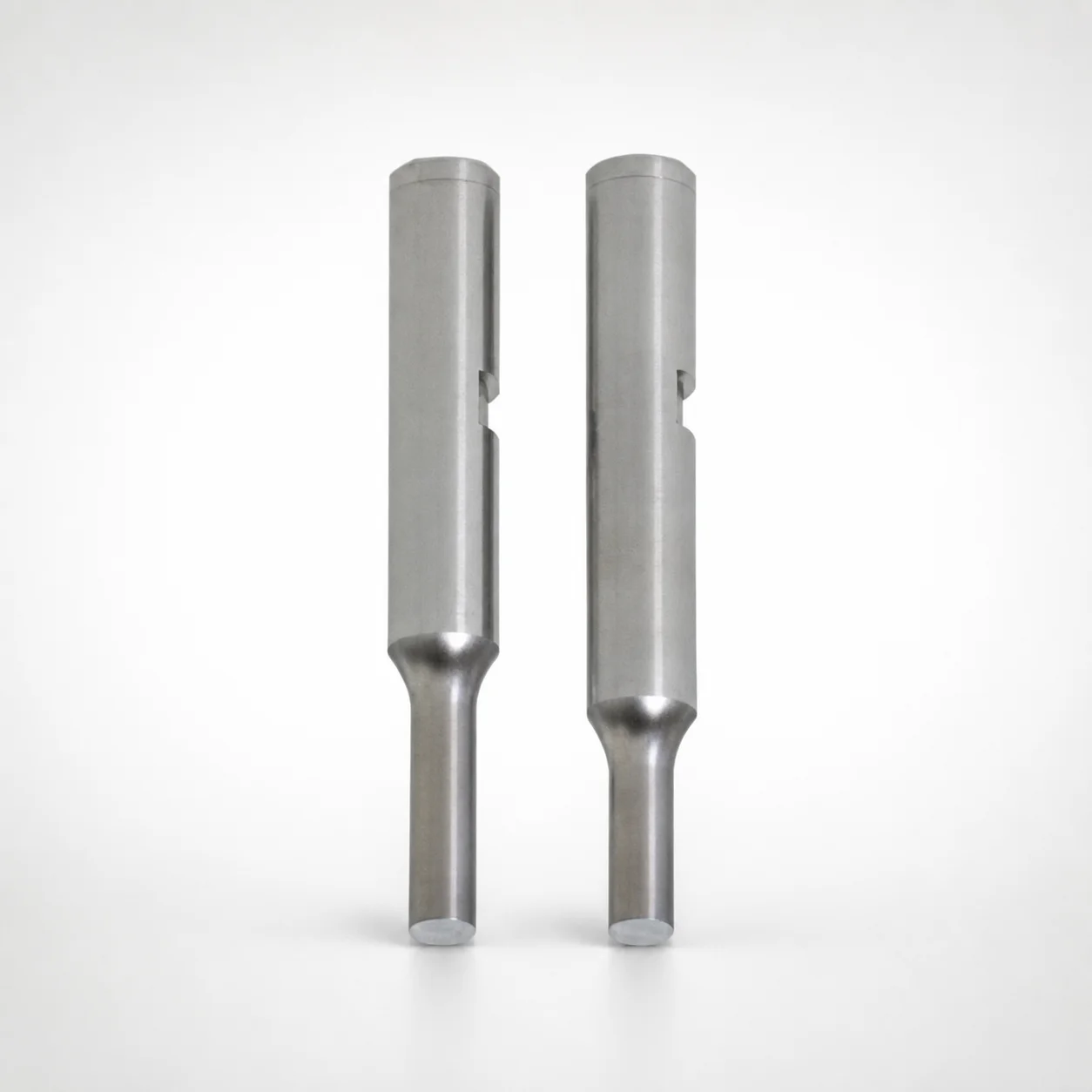
Punches with Key Grooves - RW Coating
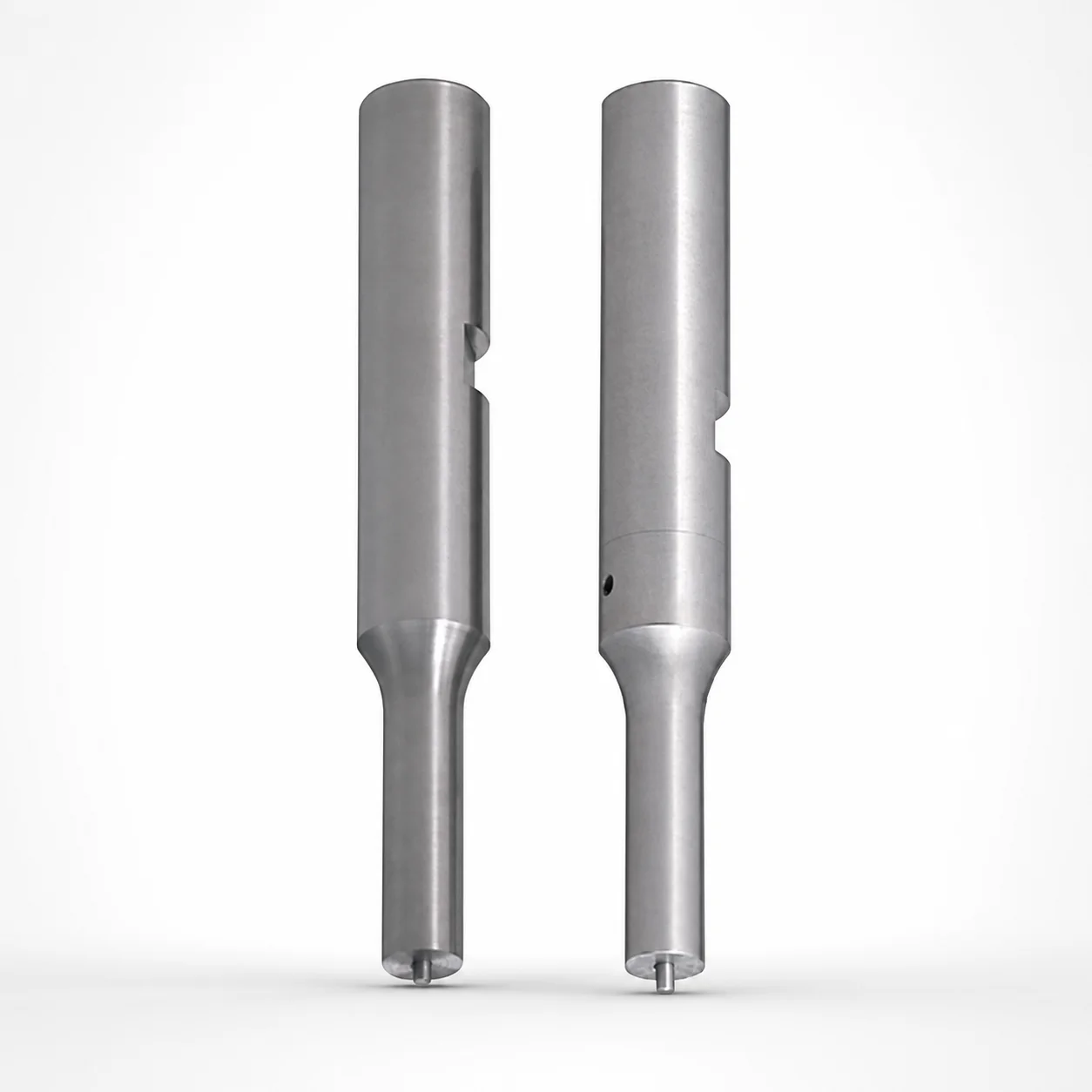
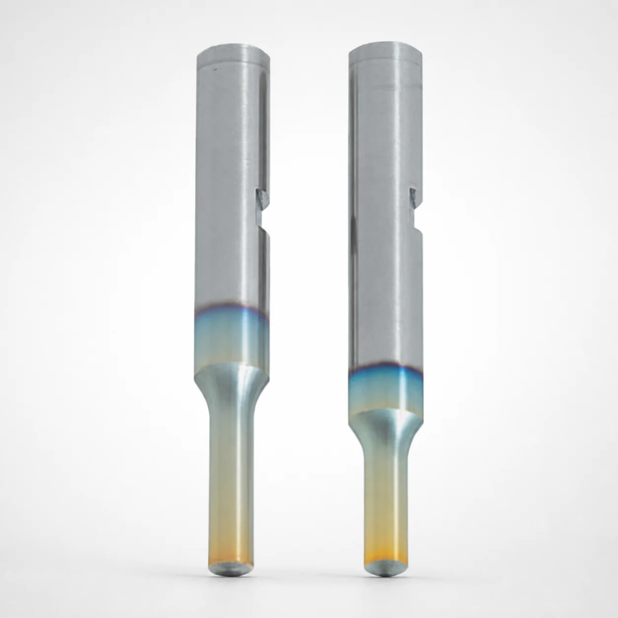
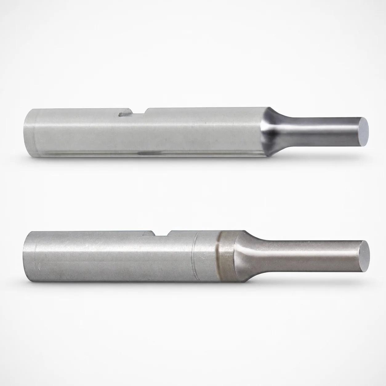
Punches with Key Grooves (RW coating) are built for accurate, repeatable punch alignment using a shank with a key groove mounting feature. The single-stepped shank design supports stable installation and efficient die operation.
- Key groove shank helps prevent rotation for consistent punching results
- RW coating enhances wear resistance for longer tool service life
- Supports tight fit requirements with controlled shank mounting geometry
- Commonly used for progressive and transfer dies requiring reliable punch position
Specifications
3552 configurations available
| Tip shape | Material | Shank diameter D tolerance | B (Tip length) | D (Shank diameter) (mm) | P (Tip dimension) (mm) | L (L Dimension) (mm) | LC (Full length alteration) (mm) | LCT (Head thickness tolerance change + total length alteration) (mm) | PC (Tip dimension alteration) (mm) | R (Tip corner R) (mm) | T (Key groove position) (mm) | W (Tip dimension) (mm) | WC (Tip dimension alteration) (mm) | type |
|---|---|---|---|---|---|---|---|---|---|---|---|---|---|---|
| A | Powdered high-speed steel | +0.005/0 | L | 3 | 1 ~ 2.99 | 50 ~ 80 | - | - | - | - | 5.1 ~ 80 | - | - | - |
| A | Powdered high-speed steel | +0.005/0 | L | 3 | - | 50 ~ 80 | - | - | 0.5 ~ 0.99 | - | 5.1 ~ 80 | - | - | - |
| A | Powdered high-speed steel | +0.005/0 | L | 3 | 1 ~ 2.99 | - | 27 ~ 79.9 | - | - | - | 5.1 ~ 80 | - | - | - |
| A | Powdered high-speed steel | +0.005/0 | L | 3 | - | - | 27 ~ 79.9 | - | 0.5 ~ 0.99 | - | 5.1 ~ 80 | - | - | - |
| A | Powdered high-speed steel | +0.005/0 | L | 3 | 1 ~ 2.99 | - | - | 27 ~ 79.9 | - | - | 5.1 ~ 80 | - | - | - |
| A | Powdered high-speed steel | +0.005/0 | L | 3 | - | - | - | 27 ~ 79.9 | 0.5 ~ 0.99 | - | 5.1 ~ 80 | - | - | - |
| A | Powdered high-speed steel | +0.005/0 | L | 4 | 1 ~ 3.99 | 50 ~ 80 | - | - | - | - | 5.1 ~ 80 | - | - | - |
| A | Powdered high-speed steel | +0.005/0 | L | 4 | - | 50 ~ 80 | - | - | 0.5 ~ 0.99 | - | 5.1 ~ 80 | - | - | - |
| A | Powdered high-speed steel | +0.005/0 | L | 4 | 1 ~ 3.99 | - | 27 ~ 79.9 | - | - | - | 5.1 ~ 80 | - | - | - |
| A | Powdered high-speed steel | +0.005/0 | L | 4 | - | - | 27 ~ 79.9 | - | 0.5 ~ 0.99 | - | 5.1 ~ 80 | - | - | - |
| A | Powdered high-speed steel | +0.005/0 | L | 4 | 1 ~ 3.99 | - | - | 27 ~ 79.9 | - | - | 5.1 ~ 80 | - | - | - |
| A | Powdered high-speed steel | +0.005/0 | L | 4 | - | - | - | 27 ~ 79.9 | 0.5 ~ 0.99 | - | 5.1 ~ 80 | - | - | - |
| A | Powdered high-speed steel | +0.005/0 | L | 5 | 2 ~ 4.99 | 50 ~ 80 | - | - | - | - | 5.1 ~ 80 | - | - | - |
| A | Powdered high-speed steel | +0.005/0 | L | 5 | - | 50 ~ 80 | - | - | 1 ~ 1.99 | - | 5.1 ~ 80 | - | - | - |
| A | Powdered high-speed steel | +0.005/0 | L | 5 | 2 ~ 4.99 | - | 27 ~ 79.9 | - | - | - | 5.1 ~ 80 | - | - | - |
| A | Powdered high-speed steel | +0.005/0 | L | 5 | - | - | 27 ~ 79.9 | - | 1 ~ 1.99 | - | 5.1 ~ 80 | - | - | - |
| A | Powdered high-speed steel | +0.005/0 | L | 5 | 2 ~ 4.99 | - | - | 27 ~ 79.9 | - | - | 5.1 ~ 80 | - | - | - |
| A | Powdered high-speed steel | +0.005/0 | L | 5 | - | - | - | 27 ~ 79.9 | 1 ~ 1.99 | - | 5.1 ~ 80 | - | - | - |
| A | Powdered high-speed steel | +0.005/0 | L | 6 | 2 ~ 5.99 | 50 ~ 80 | - | - | - | - | 5.1 ~ 80 | - | - | - |
| A | Powdered high-speed steel | +0.005/0 | L | 6 | - | 50 ~ 80 | - | - | 1 ~ 1.99 | - | 5.1 ~ 80 | - | - | - |
| A | Powdered high-speed steel | +0.005/0 | L | 6 | 2 ~ 5.99 | - | 27 ~ 79.9 | - | - | - | 5.1 ~ 80 | - | - | - |
| A | Powdered high-speed steel | +0.005/0 | L | 6 | - | - | 27 ~ 79.9 | - | 1 ~ 1.99 | - | 5.1 ~ 80 | - | - | - |
| A | Powdered high-speed steel | +0.005/0 | L | 6 | 2 ~ 5.99 | - | - | 27 ~ 79.9 | - | - | 5.1 ~ 80 | - | - | - |
| A | Powdered high-speed steel | +0.005/0 | L | 6 | - | - | - | 27 ~ 79.9 | 1 ~ 1.99 | - | 5.1 ~ 80 | - | - | - |
| A | Powdered high-speed steel | +0.005/0 | L | 8 | 3 ~ 7.99 | 50 ~ 100 | - | - | - | - | 5.1 ~ 100 | - | - | - |
| A | Powdered high-speed steel | +0.005/0 | L | 8 | - | 50 ~ 100 | - | - | 1.5 ~ 2.99 | - | 5.1 ~ 100 | - | - | - |
| A | Powdered high-speed steel | +0.005/0 | L | 8 | 3 ~ 7.99 | - | 27 ~ 99.9 | - | - | - | 5.1 ~ 100 | - | - | - |
| A | Powdered high-speed steel | +0.005/0 | L | 8 | - | - | 27 ~ 99.9 | - | 1.5 ~ 2.99 | - | 5.1 ~ 100 | - | - | - |
| A | Powdered high-speed steel | +0.005/0 | L | 8 | 3 ~ 7.99 | - | - | 27 ~ 99.9 | - | - | 5.1 ~ 100 | - | - | - |
| A | Powdered high-speed steel | +0.005/0 | L | 8 | - | - | - | 27 ~ 99.9 | 1.5 ~ 2.99 | - | 5.1 ~ 100 | - | - | - |
| A | Powdered high-speed steel | +0.005/0 | L | 10 | 3 ~ 9.99 | 50 ~ 100 | - | - | - | - | 5.1 ~ 100 | - | - | - |
| A | Powdered high-speed steel | +0.005/0 | L | 10 | - | 50 ~ 100 | - | - | 1.5 ~ 2.99 | - | 5.1 ~ 100 | - | - | - |
| A | Powdered high-speed steel | +0.005/0 | L | 10 | 3 ~ 9.99 | - | 27 ~ 99.9 | - | - | - | 5.1 ~ 100 | - | - | - |
| A | Powdered high-speed steel | +0.005/0 | L | 10 | - | - | 27 ~ 99.9 | - | 1.5 ~ 2.99 | - | 5.1 ~ 100 | - | - | - |
| A | Powdered high-speed steel | +0.005/0 | L | 10 | 3 ~ 9.99 | - | - | 27 ~ 99.9 | - | - | 5.1 ~ 100 | - | - | - |
| A | Powdered high-speed steel | +0.005/0 | L | 10 | - | - | - | 27 ~ 99.9 | 1.5 ~ 2.99 | - | 5.1 ~ 100 | - | - | - |
| A | Powdered high-speed steel | +0.005/0 | L | 13 | 6 ~ 12.99 | 50 ~ 100 | - | - | - | - | 5.1 ~ 100 | - | - | - |
| A | Powdered high-speed steel | +0.005/0 | L | 13 | - | 50 ~ 100 | - | - | 3 ~ 5.99 | - | 5.1 ~ 100 | - | - | - |
| A | Powdered high-speed steel | +0.005/0 | L | 13 | 6 ~ 12.99 | - | 27 ~ 99.9 | - | - | - | 5.1 ~ 100 | - | - | - |
| A | Powdered high-speed steel | +0.005/0 | L | 13 | - | - | 27 ~ 99.9 | - | 3 ~ 5.99 | - | 5.1 ~ 100 | - | - | - |
| A | Powdered high-speed steel | +0.005/0 | L | 13 | 6 ~ 12.99 | - | - | 27 ~ 99.9 | - | - | 5.1 ~ 100 | - | - | - |
| A | Powdered high-speed steel | +0.005/0 | L | 13 | - | - | - | 27 ~ 99.9 | 3 ~ 5.99 | - | 5.1 ~ 100 | - | - | - |
| A | Powdered high-speed steel | +0.005/0 | L | 16 | 10 ~ 15.99 | 60 ~ 100 | - | - | - | - | 5.1 ~ 100 | - | - | - |
| A | Powdered high-speed steel | +0.005/0 | L | 16 | - | 60 ~ 100 | - | - | 5 ~ 9.99 | - | 5.1 ~ 100 | - | - | - |
| A | Powdered high-speed steel | +0.005/0 | L | 16 | 10 ~ 15.99 | - | 27 ~ 99.9 | - | - | - | 5.1 ~ 100 | - | - | - |
| A | Powdered high-speed steel | +0.005/0 | L | 16 | - | - | 27 ~ 99.9 | - | 5 ~ 9.99 | - | 5.1 ~ 100 | - | - | - |
| A | Powdered high-speed steel | +0.005/0 | L | 16 | 10 ~ 15.99 | - | - | 27 ~ 99.9 | - | - | 5.1 ~ 100 | - | - | - |
| A | Powdered high-speed steel | +0.005/0 | L | 16 | - | - | - | 27 ~ 99.9 | 5 ~ 9.99 | - | 5.1 ~ 100 | - | - | - |
| A | Powdered high-speed steel | +0.005/0 | S | 3 | 1 ~ 2.99 | 40 ~ 80 | - | - | - | - | 5.1 ~ 80 | - | - | - |
| A | Powdered high-speed steel | +0.005/0 | S | 3 | - | 40 ~ 80 | - | - | 0.5 ~ 0.99 | - | 5.1 ~ 80 | - | - | - |
Product Guide
Application Scenarios+
This punch variant is used in injection mold tooling and progressive/transfer die sets where the punch must maintain consistent position through repeated cycles. The single-stepped shank with key groove mounting provides positive shank alignment, reducing rotation and helping deliver repeatable stroke and cutting performance.
- Automotive connector and terminal molds: Suitable for fine-forming and trim operations where tight punch-to-die alignment is required. The key groove alignment improves repeatability, while the RW coating supports longer wear life under abrasive contacts.
- Appliance and housings progressive dies: Common for multi-station forming where the punch head sees repeated impact and sliding against die steel. The controlled shank mounting geometry helps maintain location accuracy during high-volume runs.
- Medical device component forming: Where dimensional stability and predictable tool wear matter for consistent part geometry. The RW coating helps maintain cutting edges longer, supporting stable forming results.
Choose this shank geometry when you need reliable, non-rotational mounting performance in dies and tooling.
Material & Process Details+
The listed materials are powdered high-speed steel and SKH51. SKH51 corresponds to an AISI M2-class high-speed steel, offering a balance of high red-hardness and wear resistance for cutting/forming punches.
In service, high-speed steels trade toughness for wear performance: higher hardness improves edge retention, but can reduce impact toughness compared with more ductile tool steels. With proper heat treatment (commonly quench and temper for HSS punches; exact process depends on the supplied grade/condition), the punch targets a stable hardness level typically in the ~HRC range used for HSS punches, maximizing tool life under abrasion and sliding contact.
- Powdered HSS: Refined microstructure supports improved wear uniformity.
- SKH51: Strong general-purpose HSS option for demanding punch applications.
The RW coating further enhances surface wear resistance, helping maintain dimensional stability over repeated cycles.
Sizing & Selection Guide+
Select the punch size by matching the shank diameter (D), tip geometry, and length to your die cavity/core requirements. The shank diameter range is D = 3 ~ 16 mm with a tolerance of +0.005 / 0, m5, so verify compatibility with your guide/bushing ID and mounting pocket.
- Choose tip shape: Options are A, D, E, G, R. Confirm that your die cutting/formed feature matches the tip profile.
- Set tip dimensions: P = 1 ~ 10 mm, W = 1 ~ 5 mm, and apply allowance for PC (tip dimension alteration) = 0.5 ~ 5 mm where applicable to the ordered variant.
- Match length: Head/tip length parameter B is available as L, S, X. Overall L is offered in multiple ranges (e.g., 50–80, 50–100, 60–100, 40–80, 40–100, 60–80), with corresponding LC options (e.g., 27–79.9 up to 99.9).
For repeatable positioning in dies, ensure the key groove position (T) matches the die’s mounting geometry (available ranges such as 5.1–80 and 5.1–100). Use the supplied tolerances to maintain proper fit and prevent punch rotation.
Frequently Asked Questions
Which shank diameter sizes (D) are available, and what tolerance should I consider for mounting?+
The shank diameter D is available from 3 ~ 16 mm. The specified tolerance is +0.005 / 0, m5, which should be used when checking fit against your die guide or mounting pocket. This tolerance helps maintain alignment and reduces the risk of rotational play.
How do the key groove position (T) ranges affect punch-to-die alignment?+
The key groove position T is offered in multiple ranges (e.g., 5.1 ~ 80 and 5.1 ~ 100, with additional variants). When designing or selecting your mounting block, align the die’s key features to the same T value range to ensure repeatable positioning. Mismatched key groove position can shift the punch axis and impact forming accuracy.
What tip shapes and dimensions can I specify for this punch design?+
Tip shapes are available as A, D, E, G, R. Tip dimensions include P = 1 ~ 10 mm, and W = 1 ~ 5 mm, with corner radius R = 0.15 (as listed). If you need controlled profile changes, check the provided alteration parameters such as PC (tip dimension alteration) and WC (tip dimension alteration).
How should I choose the punch length (L/LC) to match my die stack-up and stroke clearance?+
Overall length L is provided in specific ranges such as 40–80, 40–100, 50–80, 50–100, 60–80, and 60–100. Full length alteration LC is also available in multiple ranges (e.g., 27–79.9 up to 32–99.9, depending on the variant). Use these ranges to match your die stack-up and ensure correct clearance without binding at maximum punch travel.
What is the role of RW coating with SKH51 / powdered high-speed steel for punch life?+
This punch uses RW coating to enhance surface wear resistance, which is important for repeated contact against die components. The base material is either powdered high-speed steel or SKH51 (HSS, AISI M2 equivalent class). Together, the coated surface and HSS substrate help maintain edge condition and dimensional stability under abrasive sliding and forming loads.
Related Products
Need Custom Specifications?
Our engineering team can help with custom configurations, material selection, and volume pricing.