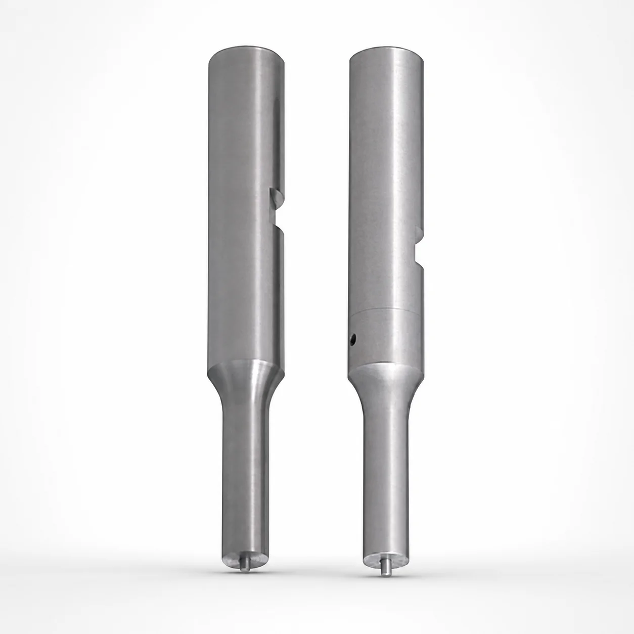
SKD11 Steel Punches with Key Grooves Single-Stepped Shank
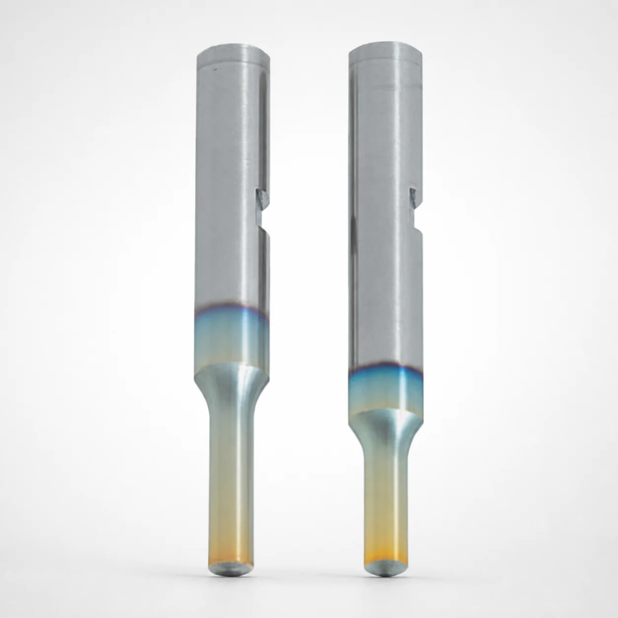
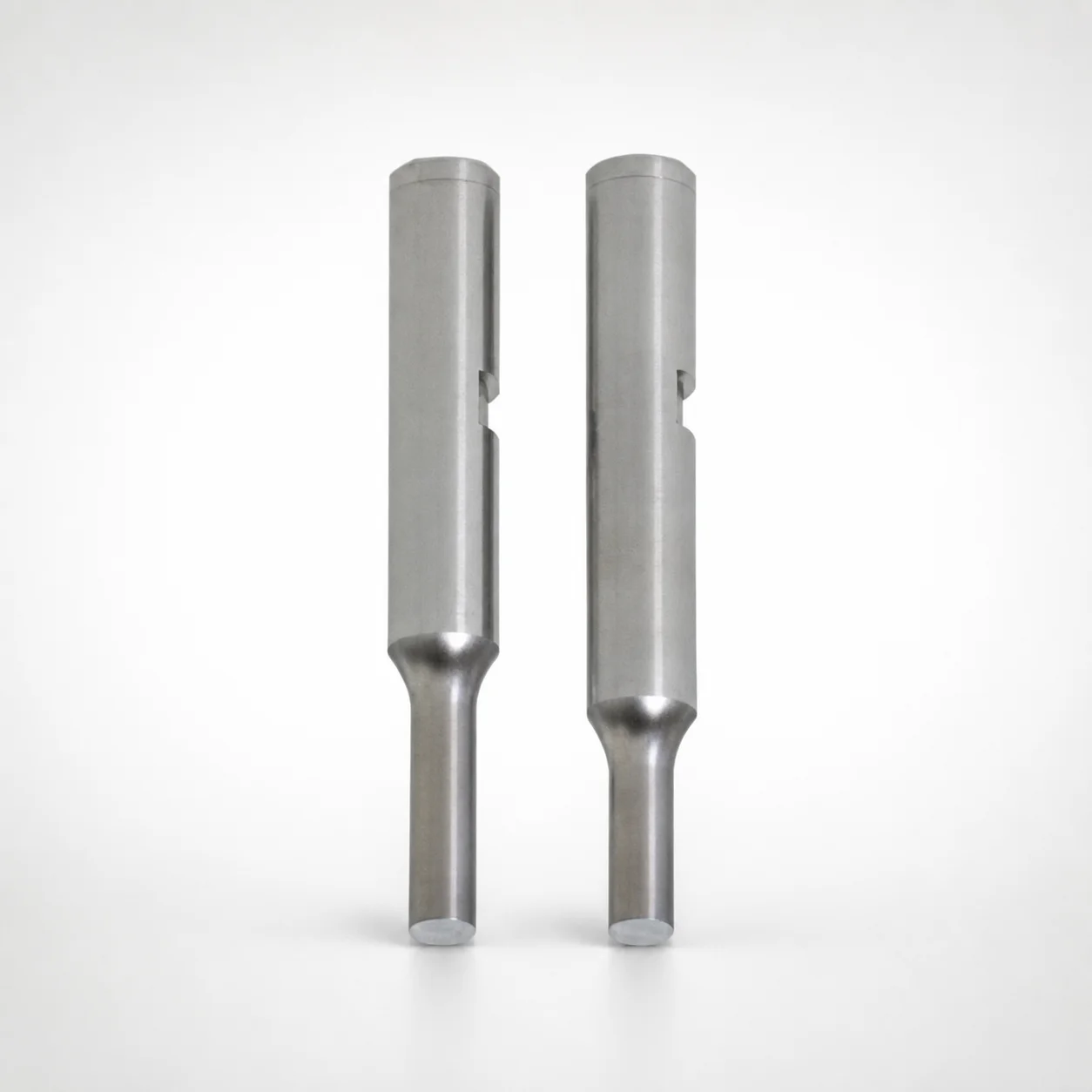
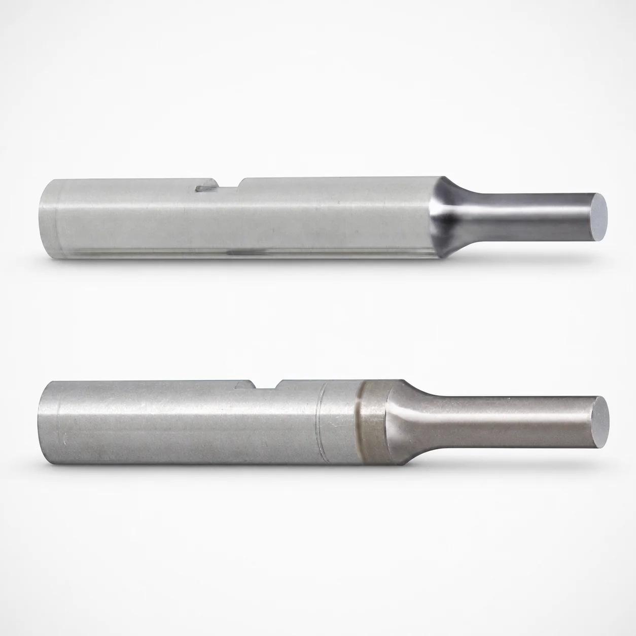
Punches with key grooves (SKD11 equivalent steel) with a single-stepped shank deliver consistent alignment and secure retention in your punch tooling. The key-groove mounting design helps prevent shifting for repeatable forming results.
- Single-stepped shank with key groove supports reliable shank positioning
- SKD11 equivalent steel construction provides strong wear resistance
- Supports controlled shank fit using m5 tolerance references for stable assembly
- Compatible with key-groove punch applications and WPC surface treatment option
Specifications
2160 configurations available
| Tip shape | Surface treatment | Shank diameter D tolerance | B (Tip length) | D (Shank diameter) (mm) | P (Tip dimension) (mm) | L (L dimension) (mm) | LC (Full length alteration) (mm) | LCT (Head thickness tolerance change + Total length alteration) (mm) | PC (Tip dimension alteration) (mm) | R (Tip corner R) (mm) | T (Key groove position) (mm) | W (Tip dimension) (mm) | WC (Tip dimension alteration) (mm) | type |
|---|---|---|---|---|---|---|---|---|---|---|---|---|---|---|
| A | None | +0.005/0 | L | 6 | 2 ~ 5.99 | 50 ~ 80 | - | - | - | - | 5.1 ~ 80 | - | - | - |
| A | None | +0.005/0 | L | 6 | - | 50 ~ 80 | - | - | 1.8 ~ 1.99 | - | 5.1 ~ 80 | - | - | - |
| A | None | +0.005/0 | L | 6 | 2 ~ 5.99 | - | 35 ~ 79.9 | - | - | - | 5.1 ~ 80 | - | - | - |
| A | None | +0.005/0 | L | 6 | - | - | 35 ~ 79.9 | - | 1.8 ~ 1.99 | - | 5.1 ~ 80 | - | - | - |
| A | None | +0.005/0 | L | 6 | 2 ~ 5.99 | - | - | 35 ~ 79.9 | - | - | 5.1 ~ 80 | - | - | - |
| A | None | +0.005/0 | L | 6 | - | - | - | 35 ~ 79.9 | 1.8 ~ 1.99 | - | 5.1 ~ 80 | - | - | - |
| A | None | +0.005/0 | L | 8 | 3 ~ 7.99 | 50 ~ 100 | - | - | - | - | 5.1 ~ 100 | - | - | - |
| A | None | +0.005/0 | L | 8 | - | 50 ~ 100 | - | - | 2.5 ~ 2.99 | - | 5.1 ~ 100 | - | - | - |
| A | None | +0.005/0 | L | 8 | 3 ~ 7.99 | - | 35 ~ 99.9 | - | - | - | 5.1 ~ 100 | - | - | - |
| A | None | +0.005/0 | L | 8 | - | - | 35 ~ 99.9 | - | 2.5 ~ 2.99 | - | 5.1 ~ 100 | - | - | - |
| A | None | +0.005/0 | L | 8 | 3 ~ 7.99 | - | - | 35 ~ 99.9 | - | - | 5.1 ~ 100 | - | - | - |
| A | None | +0.005/0 | L | 8 | - | - | - | 35 ~ 99.9 | 2.5 ~ 2.99 | - | 5.1 ~ 100 | - | - | - |
| A | None | +0.005/0 | L | 10 | 3 ~ 9.99 | 50 ~ 100 | - | - | - | - | 5.1 ~ 100 | - | - | - |
| A | None | +0.005/0 | L | 10 | - | 50 ~ 100 | - | - | 2.8 ~ 2.99 | - | 5.1 ~ 100 | - | - | - |
| A | None | +0.005/0 | L | 10 | 3 ~ 9.99 | - | 35 ~ 99.9 | - | - | - | 5.1 ~ 100 | - | - | - |
| A | None | +0.005/0 | L | 10 | - | - | 35 ~ 99.9 | - | 2.8 ~ 2.99 | - | 5.1 ~ 100 | - | - | - |
| A | None | +0.005/0 | L | 10 | 3 ~ 9.99 | - | - | 35 ~ 99.9 | - | - | 5.1 ~ 100 | - | - | - |
| A | None | +0.005/0 | L | 10 | - | - | - | 35 ~ 99.9 | 2.8 ~ 2.99 | - | 5.1 ~ 100 | - | - | - |
| A | None | +0.005/0 | L | 13 | 6 ~ 12.99 | 50 ~ 100 | - | - | - | - | 5.1 ~ 100 | - | - | - |
| A | None | +0.005/0 | L | 13 | - | 50 ~ 100 | - | - | 5 ~ 5.99 | - | 5.1 ~ 100 | - | - | - |
| A | None | +0.005/0 | L | 13 | 6 ~ 12.99 | - | 35 ~ 99.9 | - | - | - | 5.1 ~ 100 | - | - | - |
| A | None | +0.005/0 | L | 13 | - | - | 35 ~ 99.9 | - | 5 ~ 5.99 | - | 5.1 ~ 100 | - | - | - |
| A | None | +0.005/0 | L | 13 | 6 ~ 12.99 | - | - | 35 ~ 99.9 | - | - | 5.1 ~ 100 | - | - | - |
| A | None | +0.005/0 | L | 13 | - | - | - | 35 ~ 99.9 | 5 ~ 5.99 | - | 5.1 ~ 100 | - | - | - |
| A | None | +0.005/0 | L | 16 | 10 ~ 15.99 | 60 ~ 100 | - | - | - | - | 5.1 ~ 100 | - | - | - |
| A | None | +0.005/0 | L | 16 | - | 60 ~ 100 | - | - | 8 ~ 9.99 | - | 5.1 ~ 100 | - | - | - |
| A | None | +0.005/0 | L | 16 | 10 ~ 15.99 | - | 35 ~ 99.9 | - | - | - | 5.1 ~ 100 | - | - | - |
| A | None | +0.005/0 | L | 16 | - | - | 35 ~ 99.9 | - | 8 ~ 9.99 | - | 5.1 ~ 100 | - | - | - |
| A | None | +0.005/0 | L | 16 | 10 ~ 15.99 | - | - | 35 ~ 99.9 | - | - | 5.1 ~ 100 | - | - | - |
| A | None | +0.005/0 | L | 16 | - | - | - | 35 ~ 99.9 | 8 ~ 9.99 | - | 5.1 ~ 100 | - | - | - |
| A | None | +0.005/0 | S | 6 | 2 ~ 5.99 | 40 ~ 80 | - | - | - | - | 5.1 ~ 80 | - | - | - |
| A | None | +0.005/0 | S | 6 | - | 40 ~ 80 | - | - | 1.8 ~ 1.99 | - | 5.1 ~ 80 | - | - | - |
| A | None | +0.005/0 | S | 6 | 2 ~ 5.99 | - | 35 ~ 79.9 | - | - | - | 5.1 ~ 80 | - | - | - |
| A | None | +0.005/0 | S | 6 | - | - | 35 ~ 79.9 | - | 1.8 ~ 1.99 | - | 5.1 ~ 80 | - | - | - |
| A | None | +0.005/0 | S | 6 | 2 ~ 5.99 | - | - | 35 ~ 79.9 | - | - | 5.1 ~ 80 | - | - | - |
| A | None | +0.005/0 | S | 6 | - | - | - | 35 ~ 79.9 | 1.8 ~ 1.99 | - | 5.1 ~ 80 | - | - | - |
| A | None | +0.005/0 | S | 8 | 3 ~ 7.99 | 40 ~ 100 | - | - | - | - | 5.1 ~ 100 | - | - | - |
| A | None | +0.005/0 | S | 8 | - | 40 ~ 100 | - | - | 2.5 ~ 2.99 | - | 5.1 ~ 100 | - | - | - |
| A | None | +0.005/0 | S | 8 | 3 ~ 7.99 | - | 35 ~ 99.9 | - | - | - | 5.1 ~ 100 | - | - | - |
| A | None | +0.005/0 | S | 8 | - | - | 35 ~ 99.9 | - | 2.5 ~ 2.99 | - | 5.1 ~ 100 | - | - | - |
| A | None | +0.005/0 | S | 8 | 3 ~ 7.99 | - | - | 35 ~ 99.9 | - | - | 5.1 ~ 100 | - | - | - |
| A | None | +0.005/0 | S | 8 | - | - | - | 35 ~ 99.9 | 2.5 ~ 2.99 | - | 5.1 ~ 100 | - | - | - |
| A | None | +0.005/0 | S | 10 | 3 ~ 9.99 | 40 ~ 100 | - | - | - | - | 5.1 ~ 100 | - | - | - |
| A | None | +0.005/0 | S | 10 | - | 40 ~ 100 | - | - | 2.8 ~ 2.99 | - | 5.1 ~ 100 | - | - | - |
| A | None | +0.005/0 | S | 10 | 3 ~ 9.99 | - | 35 ~ 99.9 | - | - | - | 5.1 ~ 100 | - | - | - |
| A | None | +0.005/0 | S | 10 | - | - | 35 ~ 99.9 | - | 2.8 ~ 2.99 | - | 5.1 ~ 100 | - | - | - |
| A | None | +0.005/0 | S | 10 | 3 ~ 9.99 | - | - | 35 ~ 99.9 | - | - | 5.1 ~ 100 | - | - | - |
| A | None | +0.005/0 | S | 10 | - | - | - | 35 ~ 99.9 | 2.8 ~ 2.99 | - | 5.1 ~ 100 | - | - | - |
| A | None | +0.005/0 | S | 13 | 6 ~ 12.99 | 40 ~ 100 | - | - | - | - | 5.1 ~ 100 | - | - | - |
| A | None | +0.005/0 | S | 13 | - | 40 ~ 100 | - | - | 5 ~ 5.99 | - | 5.1 ~ 100 | - | - | - |
Product Guide
Application Scenarios+
These SKD11-equivalent punches with a single-stepped shank are used in progressive and compound injection and forming tooling where repeatable punch positioning is critical. The key-groove mounting supports stable shank location, reducing lateral shifting during cycling and helping maintain forming accuracy across production runs.
- Automotive electrical connector and terminal housings: ideal for small-diameter, precision openings where consistent punch-to-die alignment prevents flash and deformation. The stepped shank plus key groove improves retention under repeated loading.
- Appliance and industrial enclosure components: suited for multi-cavity tool sections requiring standardized shank fit. The provided m5 tolerance reference supports controlled assembly for repeatable forming results.
- Medical device housings and inserts: commonly used when stable forming geometry is required for tight tolerances. Choose the optional WPC surface treatment to support wear performance in demanding cycles.
Material & Process Details+
The punch is made from SKD11 steel (SKD11 equivalent), a tool-steel grade commonly selected for punch and die applications requiring wear resistance. In equivalent terms, SKD11 is referenced as H12-type performance in many tooling comparisons; actual hardness depends on final heat treatment.
- Heat treatment state: provided offerings include surface treatment options (None or WPC), intended to improve wear behavior in operation. The exact bulk hardness (HRC) and quench/temper schedule are not specified in the provided data.
- Wear vs. toughness trade-off: SKD11 is selected to balance edge wear resistance with sufficient toughness for punch work. Surface treatment (WPC) can further shift the performance toward longer wear life, particularly under abrasive or high-cycle conditions.
- Comparable variants: when choosing between None and WPC, the decision typically targets whether your application needs enhanced surface wear resistance rather than changing the base alloy.
Sizing & Selection Guide+
Select dimensions by matching the shank and key-groove geometry to your punch retainer, guiding plate, and die opening requirements. Start with the shank diameter D (available: 6, 8, 10, 13, 16 mm) to ensure the punch seats properly in the tooling.
- Shank fit tolerance: the shank diameter D tolerance is specified as +0.005/0, m5. Use an m5-compatible counterbore/guide feature to maintain stable positioning and avoid play that can increase flash.
- Tip geometry: choose tip shape (A, D, E, G, R) and match Tip dimension P (2 ~ 10 mm), Tip length B (available as L or S), and corner radius R within the listed ranges for your forming profile.
- Overall length: pick L from the provided ranges (e.g., 50–80, 50–100, 60–100, 40–80, 40–100) and verify LC (35–79.9 or 35–99.9) for your press stroke and retention stack-up.
- Key groove position T: ensure T (5.1–80 or 5.1–100 mm) aligns with the tooling key feature for positive location.
Frequently Asked Questions
How do I choose the correct shank diameter D for this single-stepped SKD11 punch?+
The available shank diameter D values are 6, 8, 10, 13, and 16 mm. Match this to your guide/punch retainer feature sized to the specified D tolerance: +0.005/0, m5 so the assembly holds position without excessive clearance.
What tip shapes and corner radii are supported for the punch geometry?+
This series supports tip shapes A, D, E, G, and R. Corner radius R is available across multiple ranges (e.g., 0.15–2.98 up to 0.15–7.98 mm depending on configuration), so confirm your forming profile before selecting the final option.
When should I select the WPC surface treatment instead of None?+
The product offers surface treatment choices: None or WPC. Select WPC when you need improved wear behavior for higher-cycle or more abrasive forming conditions, since the base material remains SKD11-equivalent.
How do LC and LCT affect overall fit in the tool stack?+
The provided ranges include LC (full length alteration) of 35–79.9 or 35–99.9 mm, and LCT (head thickness tolerance change + total length alteration) over the same respective ranges. Validate these against your press stroke, retainer thickness, and required total assembly length so the punch seats correctly without interference.
What key groove position T range should I use to match my key feature?+
The key groove position T is specified as either 5.1–80 mm or 5.1–100 mm depending on configuration. Use the option that aligns with your tooling key location to ensure positive indexing and prevent punch shifting during operation.
Related Products
Need Custom Specifications?
Our engineering team can help with custom configurations, material selection, and volume pricing.