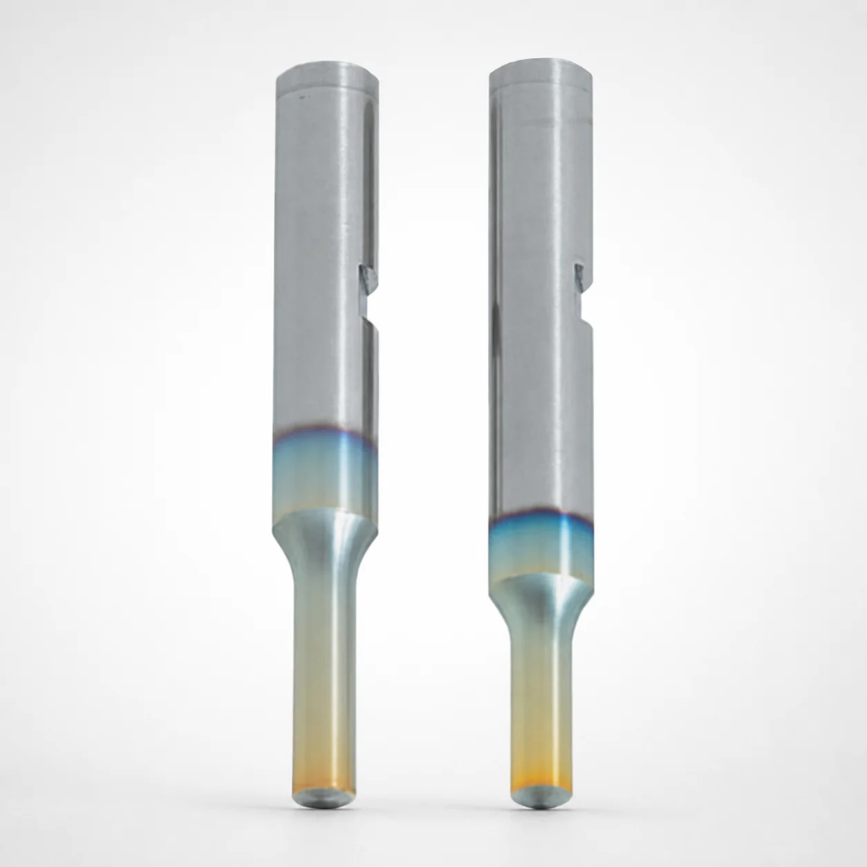
Key Groove Punches with DLC Coating WPC Treatment
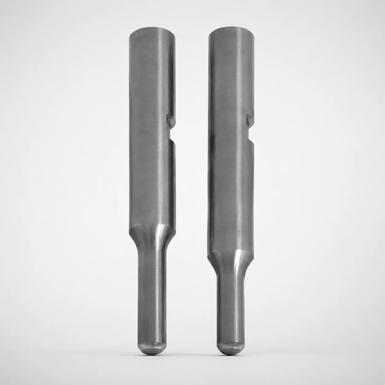
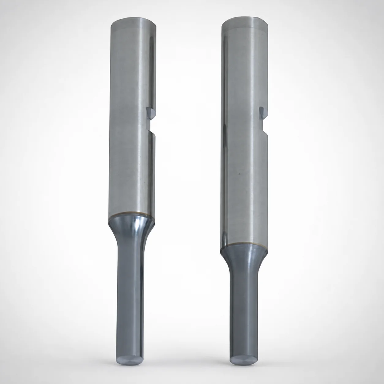
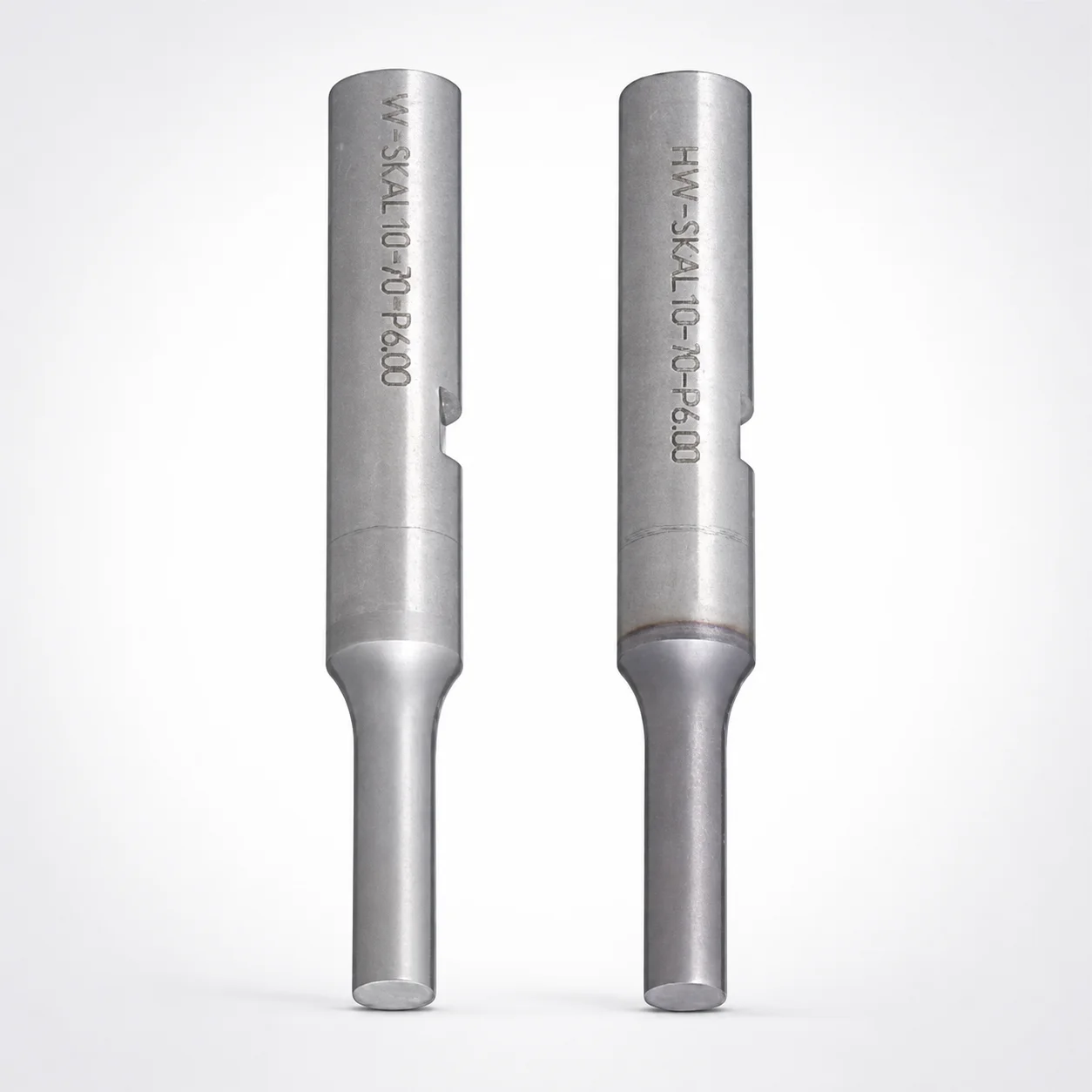
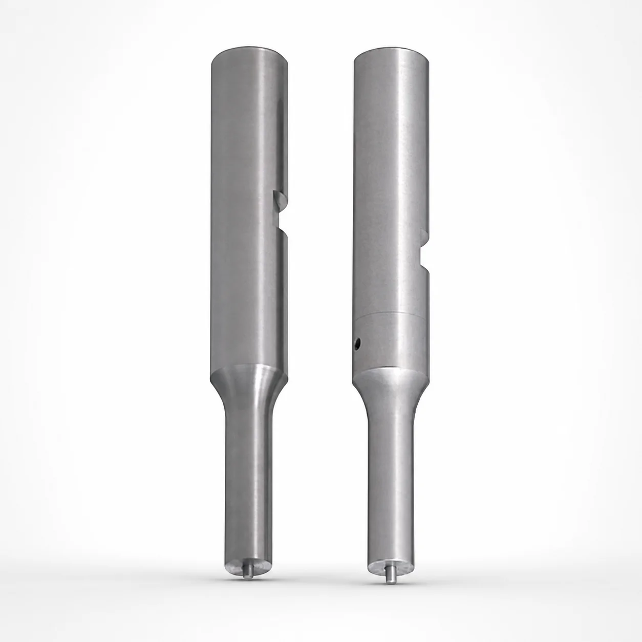
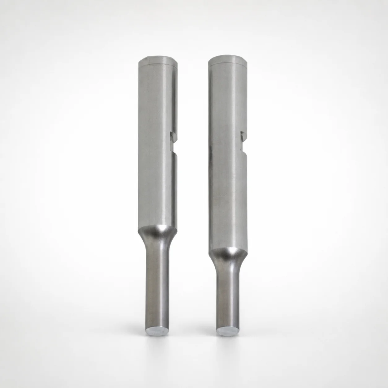
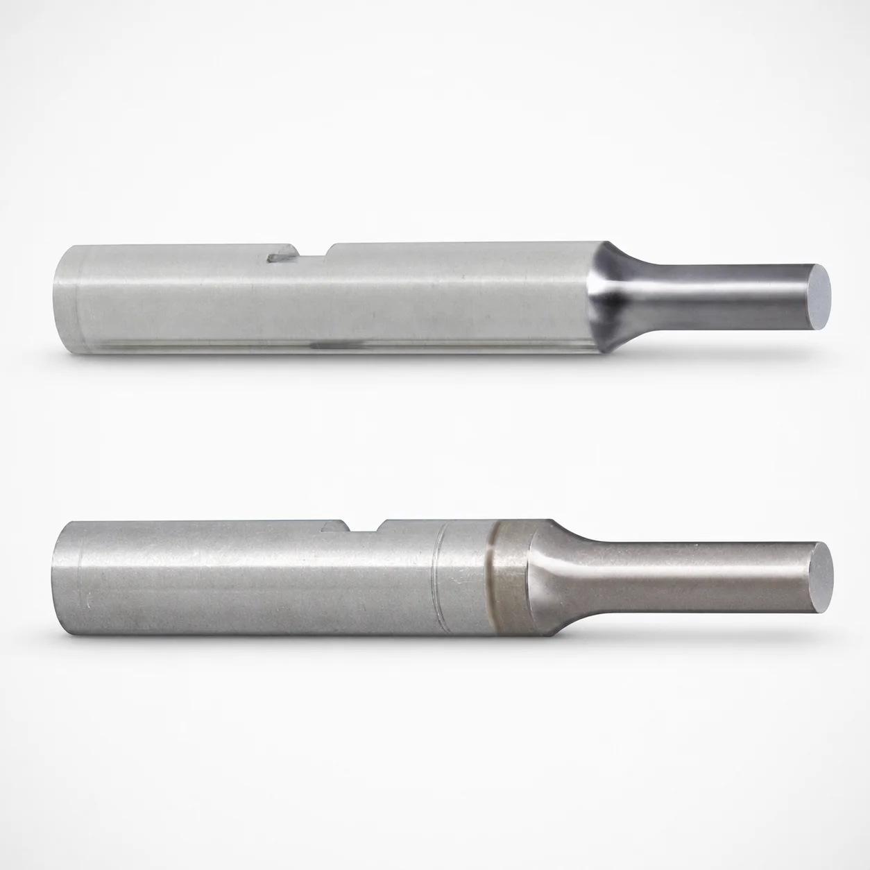
Key groove punches with DLC coating WPC treatment deliver reliable seating for punch holders using a single-stepped shank with a keyed mounting profile. The DLC-based surface system supports stable performance under repeated forming and cutting cycles.
- Single-stepped shank with key groove mounting part shape for positive location
- DLC coating with WPC foundation option helps improve wear behavior during punching
- Ground shank features a configurable fit using D tolerance reference (+0.005/0) and m5
- Used as precision punches where keyed alignment improves repeatability in dies
Specifications
6771 configurations available
| Tip shape | Material | Surface treatment | Shank diameter D tolerance | B (Tip length) | D (Shank diameter) (mm) | P (Tip dimension) (mm) | L (L dimension) (mm) | LC (Full length alteration) (mm) | LCT (Head thickness tolerance change + Total length alteration) (mm) | PC (Tip dimension alteration) (mm) | R (Tip corner R) (mm) | T (Key groove position) (mm) | W (Tip dimension) (mm) | WC (Tip dimension alteration) (mm) | type |
|---|---|---|---|---|---|---|---|---|---|---|---|---|---|---|---|
| A | Powdered high-speed steel | Without DLC foundation | +0.005/0 | L | 3 | 1 ~ 2.99 | 50 ~ 80 | - | - | - | - | 5.1 ~ 80 | - | - | - |
| A | Powdered high-speed steel | Without DLC foundation | +0.005/0 | L | 3 | 1 ~ 2.99 | - | 32 ~ 79.9 | - | - | - | 5.1 ~ 80 | - | - | - |
| A | Powdered high-speed steel | Without DLC foundation | +0.005/0 | L | 3 | 1 ~ 2.99 | - | - | 32 ~ 79.9 | - | - | 5.1 ~ 80 | - | - | - |
| A | Powdered high-speed steel | Without DLC foundation | +0.005/0 | L | 4 | 1 ~ 3.99 | 50 ~ 80 | - | - | - | - | 5.1 ~ 80 | - | - | - |
| A | Powdered high-speed steel | Without DLC foundation | +0.005/0 | L | 4 | 1 ~ 3.99 | - | 32 ~ 79.9 | - | - | - | 5.1 ~ 80 | - | - | - |
| A | Powdered high-speed steel | Without DLC foundation | +0.005/0 | L | 4 | 1 ~ 3.99 | - | - | 32 ~ 79.9 | - | - | 5.1 ~ 80 | - | - | - |
| A | Powdered high-speed steel | Without DLC foundation | +0.005/0 | L | 5 | 2 ~ 4.99 | 50 ~ 80 | - | - | - | - | 5.1 ~ 80 | - | - | - |
| A | Powdered high-speed steel | Without DLC foundation | +0.005/0 | L | 5 | - | 50 ~ 80 | - | - | 1 ~ 1.99 | - | 5.1 ~ 80 | - | - | - |
| A | Powdered high-speed steel | Without DLC foundation | +0.005/0 | L | 5 | 2 ~ 4.99 | - | 32 ~ 79.9 | - | - | - | 5.1 ~ 80 | - | - | - |
| A | Powdered high-speed steel | Without DLC foundation | +0.005/0 | L | 5 | - | - | 32 ~ 79.9 | - | 1 ~ 1.99 | - | 5.1 ~ 80 | - | - | - |
| A | Powdered high-speed steel | Without DLC foundation | +0.005/0 | L | 5 | 2 ~ 4.99 | - | - | 32 ~ 79.9 | - | - | 5.1 ~ 80 | - | - | - |
| A | Powdered high-speed steel | Without DLC foundation | +0.005/0 | L | 5 | - | - | - | 32 ~ 79.9 | 1 ~ 1.99 | - | 5.1 ~ 80 | - | - | - |
| A | Powdered high-speed steel | Without DLC foundation | +0.005/0 | L | 6 | 2 ~ 5.99 | 50 ~ 80 | - | - | - | - | 5.1 ~ 80 | - | - | - |
| A | Powdered high-speed steel | Without DLC foundation | +0.005/0 | L | 6 | - | 50 ~ 80 | - | - | 1 ~ 1.99 | - | 5.1 ~ 80 | - | - | - |
| A | Powdered high-speed steel | Without DLC foundation | +0.005/0 | L | 6 | 2 ~ 5.99 | - | 32 ~ 79.9 | - | - | - | 5.1 ~ 80 | - | - | - |
| A | Powdered high-speed steel | Without DLC foundation | +0.005/0 | L | 6 | - | - | 32 ~ 79.9 | - | 1 ~ 1.99 | - | 5.1 ~ 80 | - | - | - |
| A | Powdered high-speed steel | Without DLC foundation | +0.005/0 | L | 6 | 2 ~ 5.99 | - | - | 32 ~ 79.9 | - | - | 5.1 ~ 80 | - | - | - |
| A | Powdered high-speed steel | Without DLC foundation | +0.005/0 | L | 6 | - | - | - | 32 ~ 79.9 | 1 ~ 1.99 | - | 5.1 ~ 80 | - | - | - |
| A | Powdered high-speed steel | Without DLC foundation | +0.005/0 | L | 8 | 3 ~ 7.99 | 50 ~ 100 | - | - | - | - | 5.1 ~ 100 | - | - | - |
| A | Powdered high-speed steel | Without DLC foundation | +0.005/0 | L | 8 | - | 50 ~ 100 | - | - | 1.5 ~ 2.99 | - | 5.1 ~ 100 | - | - | - |
| A | Powdered high-speed steel | Without DLC foundation | +0.005/0 | L | 8 | 3 ~ 7.99 | - | 32 ~ 99.9 | - | - | - | 5.1 ~ 100 | - | - | - |
| A | Powdered high-speed steel | Without DLC foundation | +0.005/0 | L | 8 | - | - | 32 ~ 99.9 | - | 1.5 ~ 2.99 | - | 5.1 ~ 100 | - | - | - |
| A | Powdered high-speed steel | Without DLC foundation | +0.005/0 | L | 8 | 3 ~ 7.99 | - | - | 32 ~ 99.9 | - | - | 5.1 ~ 100 | - | - | - |
| A | Powdered high-speed steel | Without DLC foundation | +0.005/0 | L | 8 | - | - | - | 32 ~ 99.9 | 1.5 ~ 2.99 | - | 5.1 ~ 100 | - | - | - |
| A | Powdered high-speed steel | Without DLC foundation | +0.005/0 | L | 10 | 3 ~ 9.99 | 50 ~ 100 | - | - | - | - | 5.1 ~ 100 | - | - | - |
| A | Powdered high-speed steel | Without DLC foundation | +0.005/0 | L | 10 | - | 50 ~ 100 | - | - | 1.5 ~ 2.99 | - | 5.1 ~ 100 | - | - | - |
| A | Powdered high-speed steel | Without DLC foundation | +0.005/0 | L | 10 | 3 ~ 9.99 | - | 32 ~ 99.9 | - | - | - | 5.1 ~ 100 | - | - | - |
| A | Powdered high-speed steel | Without DLC foundation | +0.005/0 | L | 10 | - | - | 32 ~ 99.9 | - | 1.5 ~ 2.99 | - | 5.1 ~ 100 | - | - | - |
| A | Powdered high-speed steel | Without DLC foundation | +0.005/0 | L | 10 | 3 ~ 9.99 | - | - | 32 ~ 99.9 | - | - | 5.1 ~ 100 | - | - | - |
| A | Powdered high-speed steel | Without DLC foundation | +0.005/0 | L | 10 | - | - | - | 32 ~ 99.9 | 1.5 ~ 2.99 | - | 5.1 ~ 100 | - | - | - |
| A | Powdered high-speed steel | Without DLC foundation | +0.005/0 | L | 13 | 6 ~ 12.99 | 50 ~ 100 | - | - | - | - | 5.1 ~ 100 | - | - | - |
| A | Powdered high-speed steel | Without DLC foundation | +0.005/0 | L | 13 | - | 50 ~ 100 | - | - | 3 ~ 5.99 | - | 5.1 ~ 100 | - | - | - |
| A | Powdered high-speed steel | Without DLC foundation | +0.005/0 | L | 13 | 6 ~ 12.99 | - | 32 ~ 99.9 | - | - | - | 5.1 ~ 100 | - | - | - |
| A | Powdered high-speed steel | Without DLC foundation | +0.005/0 | L | 13 | - | - | 32 ~ 99.9 | - | 3 ~ 5.99 | - | 5.1 ~ 100 | - | - | - |
| A | Powdered high-speed steel | Without DLC foundation | +0.005/0 | L | 13 | 6 ~ 12.99 | - | - | 32 ~ 99.9 | - | - | 5.1 ~ 100 | - | - | - |
| A | Powdered high-speed steel | Without DLC foundation | +0.005/0 | L | 13 | - | - | - | 32 ~ 99.9 | 3 ~ 5.99 | - | 5.1 ~ 100 | - | - | - |
| A | Powdered high-speed steel | Without DLC foundation | +0.005/0 | L | 16 | 10 ~ 15.99 | 60 ~ 100 | - | - | - | - | 5.1 ~ 100 | - | - | - |
| A | Powdered high-speed steel | Without DLC foundation | +0.005/0 | L | 16 | - | 60 ~ 100 | - | - | 5 ~ 9.99 | - | 5.1 ~ 100 | - | - | - |
| A | Powdered high-speed steel | Without DLC foundation | +0.005/0 | L | 16 | 10 ~ 15.99 | - | 32 ~ 99.9 | - | - | - | 5.1 ~ 100 | - | - | - |
| A | Powdered high-speed steel | Without DLC foundation | +0.005/0 | L | 16 | - | - | 32 ~ 99.9 | - | 5 ~ 9.99 | - | 5.1 ~ 100 | - | - | - |
| A | Powdered high-speed steel | Without DLC foundation | +0.005/0 | L | 16 | 10 ~ 15.99 | - | - | 32 ~ 99.9 | - | - | 5.1 ~ 100 | - | - | - |
| A | Powdered high-speed steel | Without DLC foundation | +0.005/0 | L | 16 | - | - | - | 32 ~ 99.9 | 5 ~ 9.99 | - | 5.1 ~ 100 | - | - | - |
| A | Powdered high-speed steel | Without DLC foundation | +0.005/0 | S | 3 | 1 ~ 2.99 | 40 ~ 80 | - | - | - | - | 5.1 ~ 80 | - | - | - |
| A | Powdered high-speed steel | Without DLC foundation | +0.005/0 | S | 3 | 1 ~ 2.99 | - | 32 ~ 79.9 | - | - | - | 5.1 ~ 80 | - | - | - |
| A | Powdered high-speed steel | Without DLC foundation | +0.005/0 | S | 3 | 1 ~ 2.99 | - | - | 32 ~ 79.9 | - | - | 5.1 ~ 80 | - | - | - |
| A | Powdered high-speed steel | Without DLC foundation | +0.005/0 | S | 4 | 1 ~ 3.99 | 40 ~ 80 | - | - | - | - | 5.1 ~ 80 | - | - | - |
| A | Powdered high-speed steel | Without DLC foundation | +0.005/0 | S | 4 | 1 ~ 3.99 | - | 32 ~ 79.9 | - | - | - | 5.1 ~ 80 | - | - | - |
| A | Powdered high-speed steel | Without DLC foundation | +0.005/0 | S | 4 | 1 ~ 3.99 | - | - | 32 ~ 79.9 | - | - | 5.1 ~ 80 | - | - | - |
| A | Powdered high-speed steel | Without DLC foundation | +0.005/0 | S | 5 | 2 ~ 4.99 | 40 ~ 80 | - | - | - | - | 5.1 ~ 80 | - | - | - |
| A | Powdered high-speed steel | Without DLC foundation | +0.005/0 | S | 5 | - | 40 ~ 80 | - | - | 1 ~ 1.99 | - | 5.1 ~ 80 | - | - | - |
Product Guide
Application Scenarios+
These key groove punches are used in injection mold and die tooling where the punch must seat consistently and stay aligned during repeated cutting or forming. The single-stepped shank with a keyed mounting profile provides positive location, helping maintain punch-to-holder repeatability over production cycles.
- Precision automotive connector or terminal tooling: Keyed alignment improves repeatability in multi-cavity or progressive dies, reducing cumulative misalignment during successive operations.
- Medical device component forming fixtures: The DLC surface system supports stable wear behavior under repeated punching, helping maintain sharpness and dimensional consistency for small features.
- General high-cycle punching inserts: The WPC foundation option is selected when improved wear resistance and surface durability are prioritized for long run times.
Choose this variant when controlled fit at the key-groove mounting and predictable punch seating are required.
Material & Process Details+
These punches are available in powdered high-speed steel or SKH51. SKH51 corresponds to AISI M2 class high-speed steel and is commonly selected for its strong wear resistance under high-contact, cutting-style loads.
The surface system is offered as either without DLC foundation or with a DLC coating on WPC foundation (WPC). The WPC foundation variant is intended to improve durability by supporting the DLC film under repeated sliding and punching impacts.
- Hardness: The hardness is not specified in the provided data; final hardness typically depends on the supplied SKH51 grade and the heat-treatment recipe used by the manufacturer.
- Wear vs. toughness trade-off: DLC surfaces generally enhance wear resistance, while the underlying tool steel’s toughness supports resistance to chipping and edge damage.
Confirm the exact heat-treatment state and target hardness for your cavity cycle requirements during quoting.
Sizing & Selection Guide+
Selection starts with matching the punch shank and tip geometry to the corresponding punch holder and die cavity/core. This product supports shank diameter D = 3 ~ 16 mm with a specified fit reference of +0.005/0 and m5, and a keyed profile for controlled placement.
- Tip shape: Choose the required tip profile from A, D, E, G, R.
- Tip geometry: Tip dimension parameters include P = 1 ~ 10 mm, W = 1 ~ 5 mm, and tip corner radius R = 0.15 mm (as provided). Apply the allowed tip variation using PC = 0.5 ~ 5 mm and WC = 0.8 ~ 2 mm if your design requires accommodation.
- Length matching: Use L = 40 ~ 70 mm and select full length alteration ranges via LC (32 ~ 79.9 / 32 ~ 99.9 / 27 ~ 79.9 depending on configuration) to achieve correct protrusion.
Verify that the keyed groove position T = 5.1 ~ 80 mm (or up to 100 mm) matches the holder’s locating feature to prevent rotational or axial seating errors. Tolerance-sensitive interfaces should be validated with the provided D (m5) fit reference.
Frequently Asked Questions
Which tip shapes (A, D, E, G, R) are available for these key groove punches, and how do I choose one?+
What are the available materials and how does the DLC coating WPC foundation option relate to wear performance?+
How do I match the shank diameter D tolerance reference (+0.005/0, m5) when designing the punch holder interface?+
How do I select punch length using L, LC, and LCT so the protrusion is correct?+
What must be checked for keyed alignment: the key groove position T range or the shank’s keyed profile?+
Related Products
Need Custom Specifications?
Our engineering team can help with custom configurations, material selection, and volume pricing.