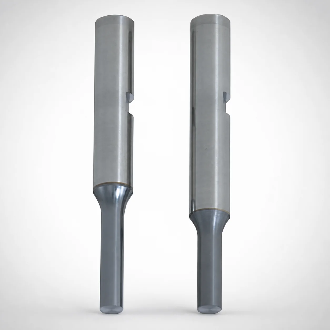
TiCN Coated Punches with Key Grooves
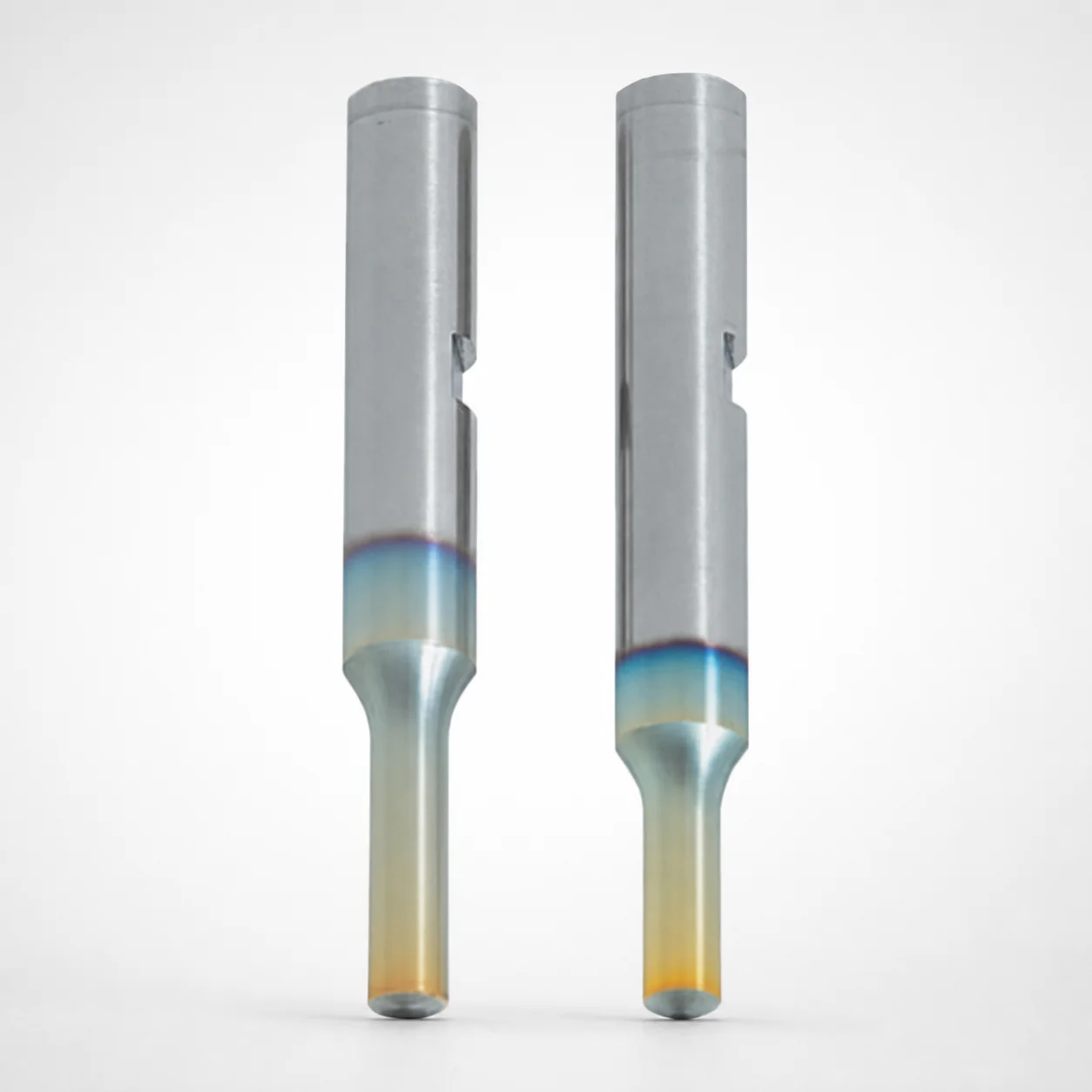
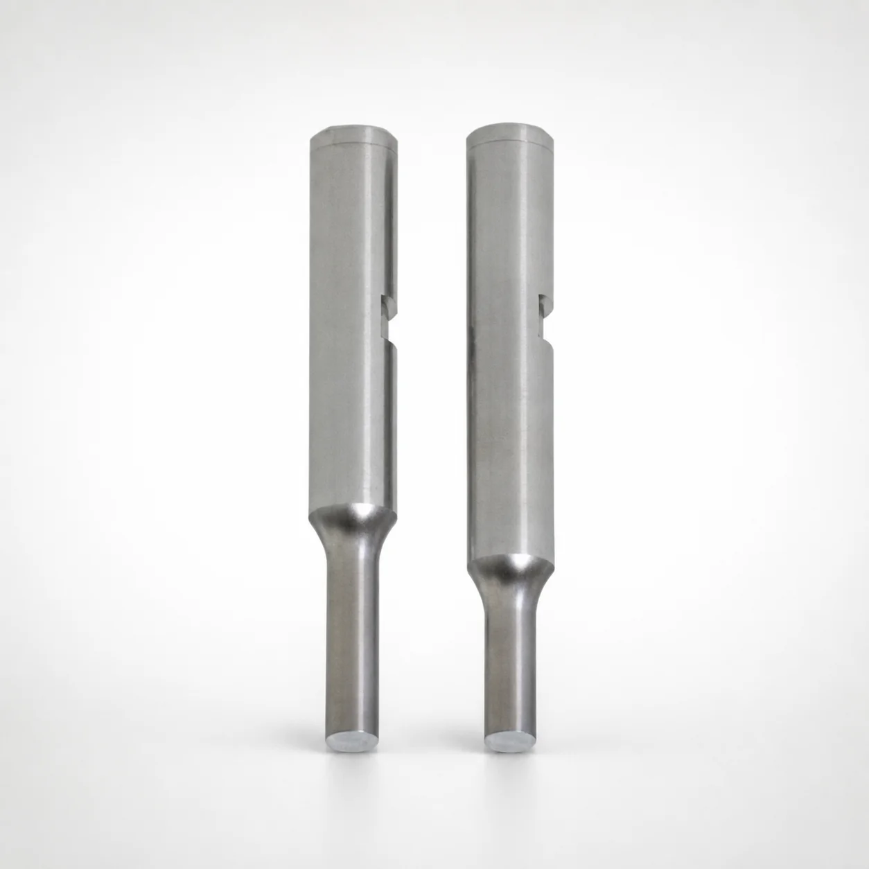
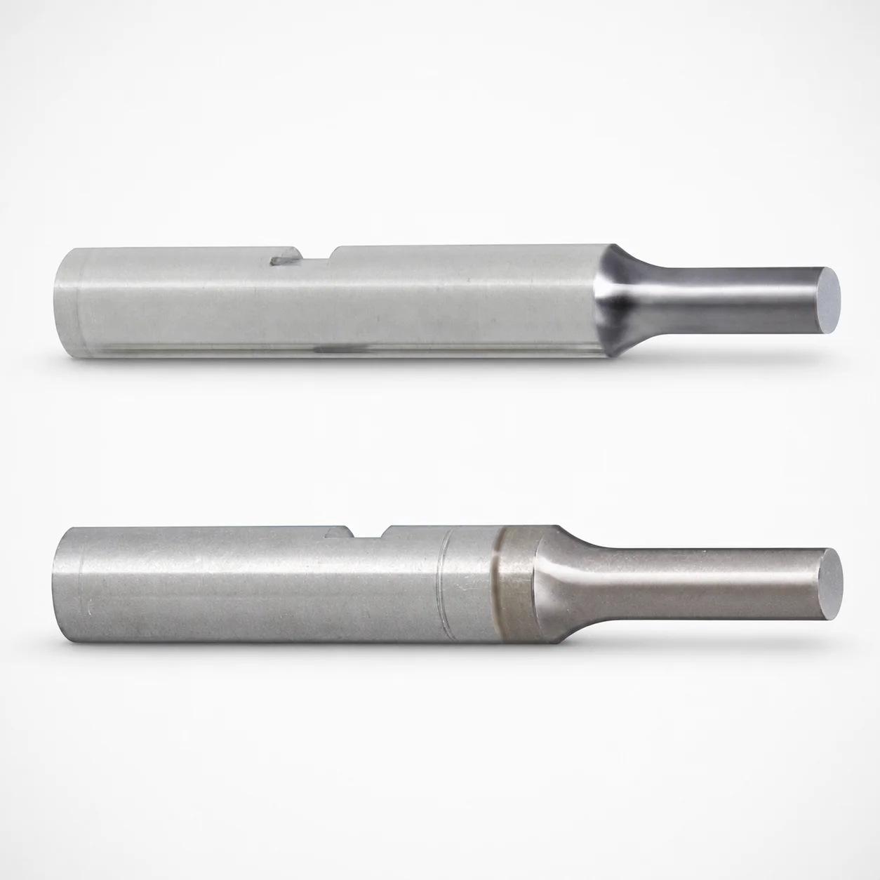
Punches with key grooves (TiCN coated) use a single-stepped shank with a key groove mounting design to improve positional stability and reliable part punching in production. The TiCN surface treatment supports abrasion resistance under demanding cycle loads.
- Single-stepped shank with key groove for consistent alignment in die sets
- TiCN coating helps resist wear and maintain tool performance during repeated punching
- Compatible with multiple tip shapes (A, D, R, E, G) to match different workpiece geometries
- Typical for progressive and transfer dies where positive locating is required
Specifications
3384 configurations available
| Tip shape | Material | Shank diameter D tolerance | B (Tip length) | D (Shank diameter) (mm) | P (Tip dimension) (mm) | L (L dimension) (mm) | LC (Full length alteration) (mm) | LCT (Head thickness tolerance change + Total length alteration) (mm) | PC (Tip dimension alteration) (mm) | R (Tip corner R) (mm) | T (Key groove position) (mm) | W (Tip dimension) (mm) | WC (Tip dimension alteration) (mm) | type |
|---|---|---|---|---|---|---|---|---|---|---|---|---|---|---|
| A | Powdered high-speed steel | +0.005/0 | L | 3 | 1 ~ 2.99 | 50 ~ 80 | - | - | - | - | 5.1 ~ 80 | - | - | - |
| A | Powdered high-speed steel | +0.005/0 | L | 3 | 1 ~ 2.99 | - | 32 ~ 79.9 | - | - | - | 5.1 ~ 80 | - | - | - |
| A | Powdered high-speed steel | +0.005/0 | L | 3 | 1 ~ 2.99 | - | - | 32 ~ 79.9 | - | - | 5.1 ~ 80 | - | - | - |
| A | Powdered high-speed steel | +0.005/0 | L | 4 | 1 ~ 3.99 | 50 ~ 80 | - | - | - | - | 5.1 ~ 80 | - | - | - |
| A | Powdered high-speed steel | +0.005/0 | L | 4 | 1 ~ 3.99 | - | 32 ~ 79.9 | - | - | - | 5.1 ~ 80 | - | - | - |
| A | Powdered high-speed steel | +0.005/0 | L | 4 | 1 ~ 3.99 | - | - | 32 ~ 79.9 | - | - | 5.1 ~ 80 | - | - | - |
| A | Powdered high-speed steel | +0.005/0 | L | 5 | 2 ~ 4.99 | 50 ~ 80 | - | - | - | - | 5.1 ~ 80 | - | - | - |
| A | Powdered high-speed steel | +0.005/0 | L | 5 | - | 50 ~ 80 | - | - | 1 ~ 1.99 | - | 5.1 ~ 80 | - | - | - |
| A | Powdered high-speed steel | +0.005/0 | L | 5 | 2 ~ 4.99 | - | 32 ~ 79.9 | - | - | - | 5.1 ~ 80 | - | - | - |
| A | Powdered high-speed steel | +0.005/0 | L | 5 | - | - | 32 ~ 79.9 | - | 1 ~ 1.99 | - | 5.1 ~ 80 | - | - | - |
| A | Powdered high-speed steel | +0.005/0 | L | 5 | 2 ~ 4.99 | - | - | 32 ~ 79.9 | - | - | 5.1 ~ 80 | - | - | - |
| A | Powdered high-speed steel | +0.005/0 | L | 5 | - | - | - | 32 ~ 79.9 | 1 ~ 1.99 | - | 5.1 ~ 80 | - | - | - |
| A | Powdered high-speed steel | +0.005/0 | L | 6 | 2 ~ 5.99 | 50 ~ 80 | - | - | - | - | 5.1 ~ 80 | - | - | - |
| A | Powdered high-speed steel | +0.005/0 | L | 6 | - | 50 ~ 80 | - | - | 1 ~ 1.99 | - | 5.1 ~ 80 | - | - | - |
| A | Powdered high-speed steel | +0.005/0 | L | 6 | 2 ~ 5.99 | - | 32 ~ 79.9 | - | - | - | 5.1 ~ 80 | - | - | - |
| A | Powdered high-speed steel | +0.005/0 | L | 6 | - | - | 32 ~ 79.9 | - | 1 ~ 1.99 | - | 5.1 ~ 80 | - | - | - |
| A | Powdered high-speed steel | +0.005/0 | L | 6 | 2 ~ 5.99 | - | - | 32 ~ 79.9 | - | - | 5.1 ~ 80 | - | - | - |
| A | Powdered high-speed steel | +0.005/0 | L | 6 | - | - | - | 32 ~ 79.9 | 1 ~ 1.99 | - | 5.1 ~ 80 | - | - | - |
| A | Powdered high-speed steel | +0.005/0 | L | 8 | 3 ~ 7.99 | 50 ~ 100 | - | - | - | - | 5.1 ~ 100 | - | - | - |
| A | Powdered high-speed steel | +0.005/0 | L | 8 | - | 50 ~ 100 | - | - | 1.5 ~ 2.99 | - | 5.1 ~ 100 | - | - | - |
| A | Powdered high-speed steel | +0.005/0 | L | 8 | 3 ~ 7.99 | - | 32 ~ 99.9 | - | - | - | 5.1 ~ 100 | - | - | - |
| A | Powdered high-speed steel | +0.005/0 | L | 8 | - | - | 32 ~ 99.9 | - | 1.5 ~ 2.99 | - | 5.1 ~ 100 | - | - | - |
| A | Powdered high-speed steel | +0.005/0 | L | 8 | 3 ~ 7.99 | - | - | 32 ~ 99.9 | - | - | 5.1 ~ 100 | - | - | - |
| A | Powdered high-speed steel | +0.005/0 | L | 8 | - | - | - | 32 ~ 99.9 | 1.5 ~ 2.99 | - | 5.1 ~ 100 | - | - | - |
| A | Powdered high-speed steel | +0.005/0 | L | 10 | 3 ~ 9.99 | 50 ~ 100 | - | - | - | - | 5.1 ~ 100 | - | - | - |
| A | Powdered high-speed steel | +0.005/0 | L | 10 | - | 50 ~ 100 | - | - | 1.5 ~ 2.99 | - | 5.1 ~ 100 | - | - | - |
| A | Powdered high-speed steel | +0.005/0 | L | 10 | 3 ~ 9.99 | - | 32 ~ 99.9 | - | - | - | 5.1 ~ 100 | - | - | - |
| A | Powdered high-speed steel | +0.005/0 | L | 10 | - | - | 32 ~ 99.9 | - | 1.5 ~ 2.99 | - | 5.1 ~ 100 | - | - | - |
| A | Powdered high-speed steel | +0.005/0 | L | 10 | 3 ~ 9.99 | - | - | 32 ~ 99.9 | - | - | 5.1 ~ 100 | - | - | - |
| A | Powdered high-speed steel | +0.005/0 | L | 10 | - | - | - | 32 ~ 99.9 | 1.5 ~ 2.99 | - | 5.1 ~ 100 | - | - | - |
| A | Powdered high-speed steel | +0.005/0 | L | 13 | 6 ~ 12.99 | 50 ~ 100 | - | - | - | - | 5.1 ~ 100 | - | - | - |
| A | Powdered high-speed steel | +0.005/0 | L | 13 | - | 50 ~ 100 | - | - | 3 ~ 5.99 | - | 5.1 ~ 100 | - | - | - |
| A | Powdered high-speed steel | +0.005/0 | L | 13 | 6 ~ 12.99 | - | 32 ~ 99.9 | - | - | - | 5.1 ~ 100 | - | - | - |
| A | Powdered high-speed steel | +0.005/0 | L | 13 | - | - | 32 ~ 99.9 | - | 3 ~ 5.99 | - | 5.1 ~ 100 | - | - | - |
| A | Powdered high-speed steel | +0.005/0 | L | 13 | 6 ~ 12.99 | - | - | 32 ~ 99.9 | - | - | 5.1 ~ 100 | - | - | - |
| A | Powdered high-speed steel | +0.005/0 | L | 13 | - | - | - | 32 ~ 99.9 | 3 ~ 5.99 | - | 5.1 ~ 100 | - | - | - |
| A | Powdered high-speed steel | +0.005/0 | L | 16 | 10 ~ 15.99 | 60 ~ 100 | - | - | - | - | 5.1 ~ 100 | - | - | - |
| A | Powdered high-speed steel | +0.005/0 | L | 16 | - | 60 ~ 100 | - | - | 5 ~ 9.99 | - | 5.1 ~ 100 | - | - | - |
| A | Powdered high-speed steel | +0.005/0 | L | 16 | 10 ~ 15.99 | - | 32 ~ 99.9 | - | - | - | 5.1 ~ 100 | - | - | - |
| A | Powdered high-speed steel | +0.005/0 | L | 16 | - | - | 32 ~ 99.9 | - | 5 ~ 9.99 | - | 5.1 ~ 100 | - | - | - |
| A | Powdered high-speed steel | +0.005/0 | L | 16 | 10 ~ 15.99 | - | - | 32 ~ 99.9 | - | - | 5.1 ~ 100 | - | - | - |
| A | Powdered high-speed steel | +0.005/0 | L | 16 | - | - | - | 32 ~ 99.9 | 5 ~ 9.99 | - | 5.1 ~ 100 | - | - | - |
| A | Powdered high-speed steel | +0.005/0 | S | 3 | 1 ~ 2.99 | 40 ~ 80 | - | - | - | - | 5.1 ~ 80 | - | - | - |
| A | Powdered high-speed steel | +0.005/0 | S | 3 | 1 ~ 2.99 | - | 32 ~ 79.9 | - | - | - | 5.1 ~ 80 | - | - | - |
| A | Powdered high-speed steel | +0.005/0 | S | 3 | 1 ~ 2.99 | - | - | 32 ~ 79.9 | - | - | 5.1 ~ 80 | - | - | - |
| A | Powdered high-speed steel | +0.005/0 | S | 4 | 1 ~ 3.99 | 40 ~ 80 | - | - | - | - | 5.1 ~ 80 | - | - | - |
| A | Powdered high-speed steel | +0.005/0 | S | 4 | 1 ~ 3.99 | - | 32 ~ 79.9 | - | - | - | 5.1 ~ 80 | - | - | - |
| A | Powdered high-speed steel | +0.005/0 | S | 4 | 1 ~ 3.99 | - | - | 32 ~ 79.9 | - | - | 5.1 ~ 80 | - | - | - |
| A | Powdered high-speed steel | +0.005/0 | S | 5 | 2 ~ 4.99 | 40 ~ 80 | - | - | - | - | 5.1 ~ 80 | - | - | - |
| A | Powdered high-speed steel | +0.005/0 | S | 5 | - | 40 ~ 80 | - | - | 1 ~ 1.99 | - | 5.1 ~ 80 | - | - | - |
Product Guide
Application Scenarios+
Punches with key grooves are used in die sets where repeatable positional stability is critical. In progressive and transfer tooling, the single-stepped shank with a key groove mounting helps lock the punch location against drift during successive station cycles, supporting consistent shearing and clean part outlines.
- Automotive connector and bracket stamping: The TiCN-coated working face improves abrasion resistance under high cycle loads, helping maintain edge geometry when punching steel and coated sheet materials.
- Electronics housings and thin-gauge metal parts: Use the variable tip shapes (A, D, R, E, G) to match specific cut profiles, while the keyed shank supports alignment across die-set build-ups.
- Appliance and metal fabrication dies: The stepped shank design is suited for multi-station die sets that require reliable orientation during setup and rework.
This variant is especially suited because the TiCN coating targets wear at the punching interface and the key groove supports repeatable seating and alignment.
Material & Process Details+
Two material options are specified for this punch series: powdered high-speed steel and SKH51. SKH51 is a high-speed steel grade commonly used for cutting tools, offering a strong balance of hardness, wear resistance, and toughness for punching applications.
- Powdered high-speed steel: Typically selected for improved uniformity and surface wear performance under repetitive cutting.
- SKH51 (HSS): Used where stable hardness and good abrasion resistance are required; the trade-off is that higher hardness can reduce impact toughness if the punching system sees severe shock or misalignment.
The working surface is TiCN coated, which increases abrasion resistance at the tip. The input data does not specify an exact post-heat-treatment hardness (HRC) or a detailed heat-treatment route; selection should be confirmed against the supplier’s processing documentation for the chosen material state (e.g., quenched & tempered for HSS or manufacturer-specific practice).
Sizing & Selection Guide+
Select the punch size by matching the shank diameter, tip geometry, and key groove location to the corresponding die-set features. The shank diameter D is specified as 3 to 16 mm, with a diameter tolerance of +0.005/0 and fit class m5; ensure the punch seats correctly in the die block bore with that fit.
- Tip shape: Choose A, D, E, G, or R to match the required cutting profile. Tip dimensions include P = 1 to 10 mm, W = 1 to 5 mm, and R (corner radius) = 0.15 mm.
- Tip length (B): Available as L, S, or X depending on the required penetration and clearance.
- Overall and head dimensions: Use L = 40 to 70 mm and full-length alteration ranges such as LC = 32 ~ 79.9, 32 ~ 99.9, 27 ~ 99.9, or 27 ~ 79.9 to align with press stroke and die thickness stack-up.
Also verify T (key groove position) = 5.1 ~ 80 (or up to 5.1 ~ 100 depending on variant) so the keyed alignment matches the die’s corresponding orientation feature.
Frequently Asked Questions
Which tip shapes (A, D, E, G, R) should be selected for different punching cut profiles?+
This series supports tip shapes A, D, E, G, and R for matching workpiece geometry and required edge form. In sizing, pair the chosen tip shape with the specified P = 1 to 10 mm and W = 1 to 5 mm dimensions, and confirm the corner radius R = 0.15 mm where applicable.
For applications requiring a more radiused corner, the R tip shape is typically selected, while the other letters correspond to distinct profile families.
What material options are available for TiCN coated key groove punches, and how do they affect wear and toughness?+
The specified material options are powdered high-speed steel and SKH51, both used with a TiCN coating to improve abrasion resistance at the punch tip. SKH51 is selected for stable hardness and wear performance typical of HSS punching tools.
Keep in mind that higher hardness grades can trade off impact toughness if the die set experiences shock from misalignment or irregular feed.
How do I select the correct shank diameter D tolerance and fit class for the die block bore?+
The shank diameter D range is 3 to 16 mm with tolerance +0.005/0 and fit class m5. When designing the die block bore, match to the intended m5 fit behavior so the keyed shank seats without excessive clearance or binding.
Confirm assembly clearances around the stepped shank and key groove orientation to prevent seating-induced misalignment.
How should I choose the overall length L / LC / LCT ranges to match die thickness and press stroke?+
This series lists L = 40 to 70 mm and provides full-length alteration ranges such as LC = 32 ~ 79.9, 32 ~ 99.9, 27 ~ 99.9, or 27 ~ 79.9, along with LCT head-thickness tolerance change with similar range groupings.
Use LC/LCT to align the punch head and tip engagement with the die stack-up and to prevent bottoming during actuation. Verify your total clearance strategy with the press stroke and stripper/ejector setup.
What key groove position T range must be matched to ensure proper alignment in the die set?+
The key groove position is specified as T = 5.1 ~ 80 and can extend to 5.1 ~ 100 depending on the selected variant. When engineering the die-set mounting features, set the die’s corresponding key/slot geometry to align with the punch’s T dimension.
This ensures the keyed shank orientation remains consistent, improving repeatability in progressive and transfer die layouts.
Related Products
Need Custom Specifications?
Our engineering team can help with custom configurations, material selection, and volume pricing.