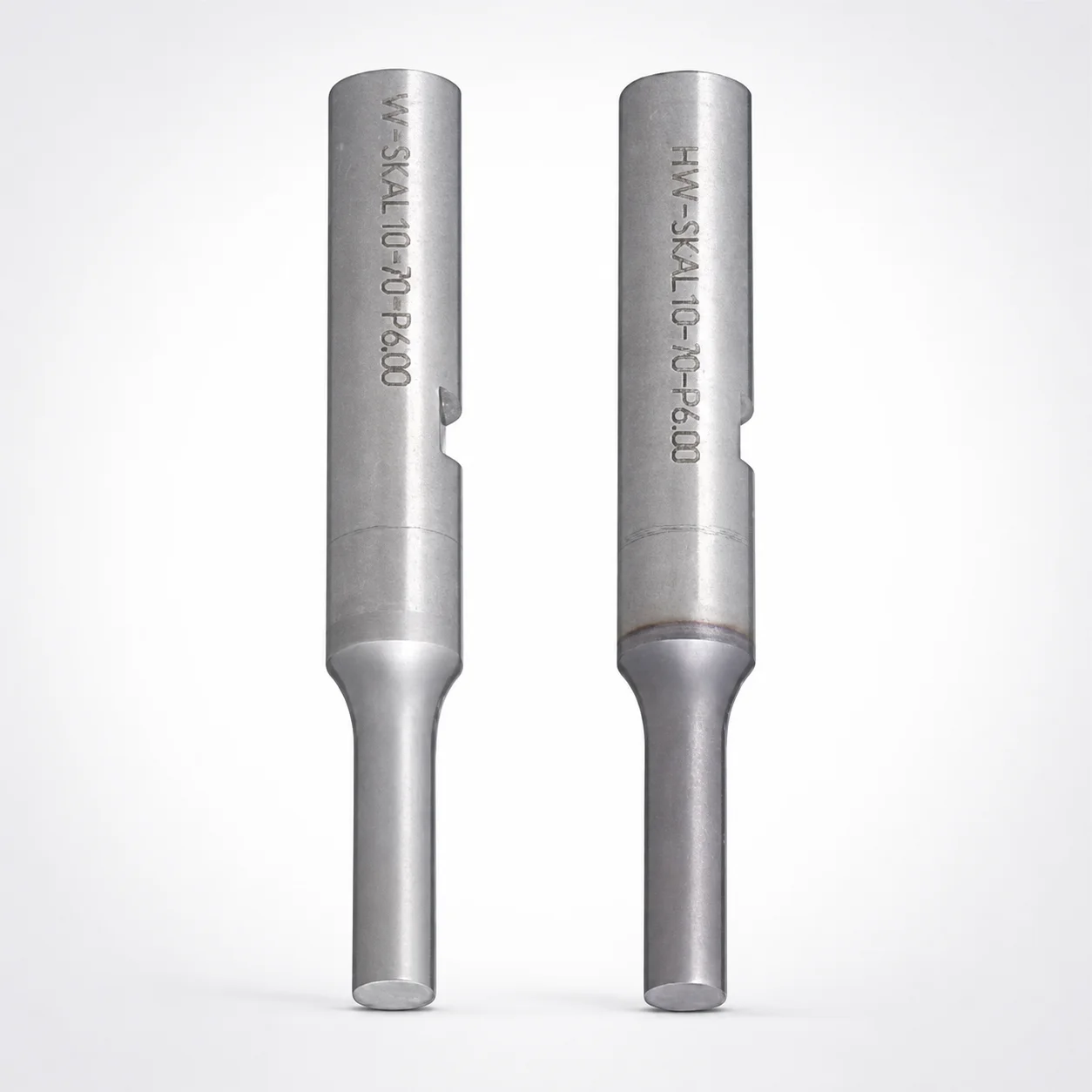
Punches with Key Grooves Single-Stepped Shank
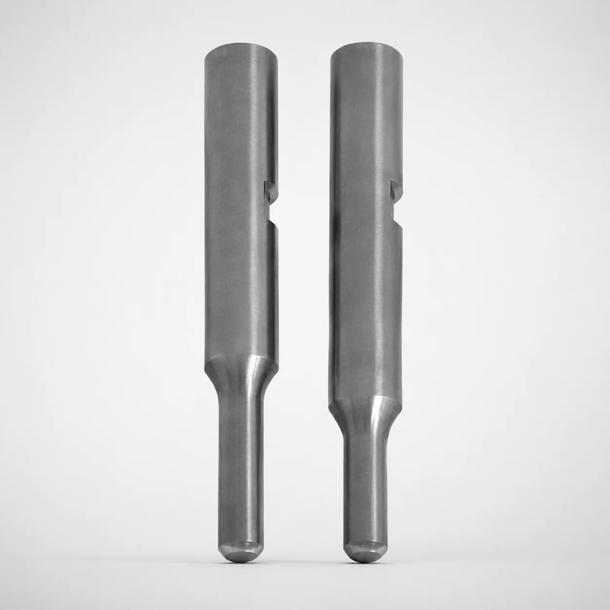
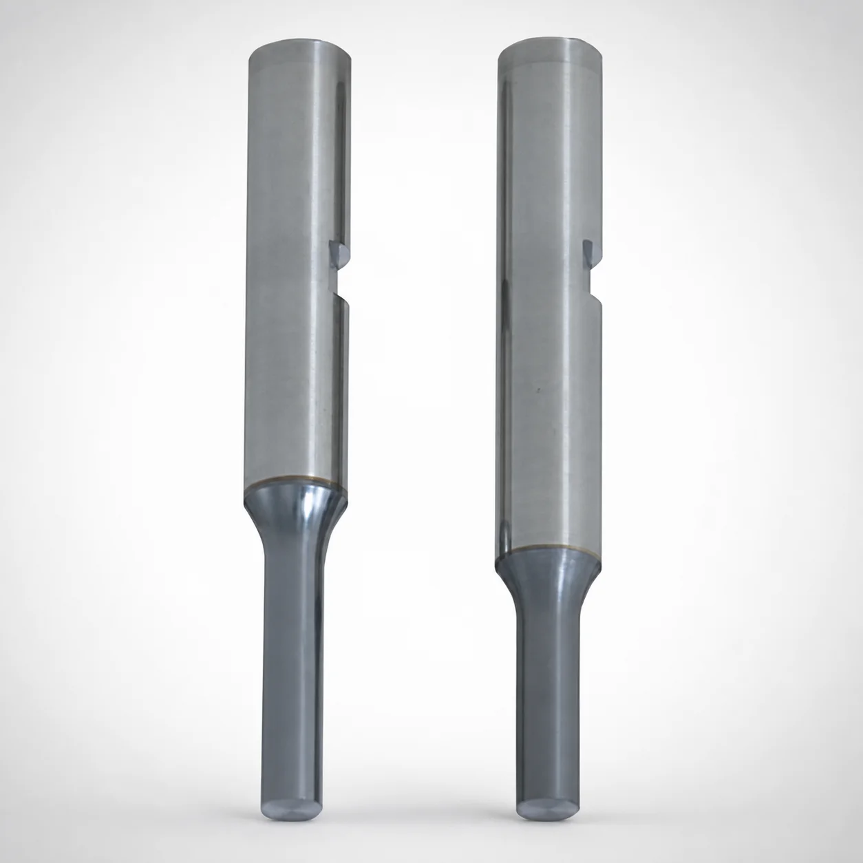
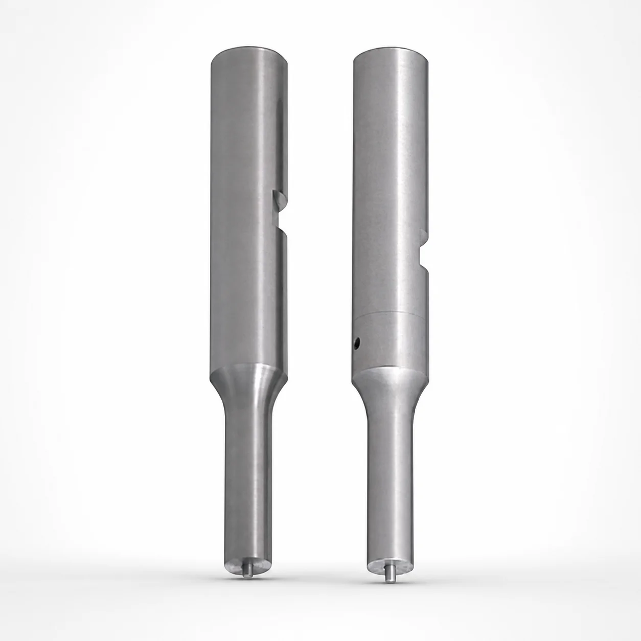
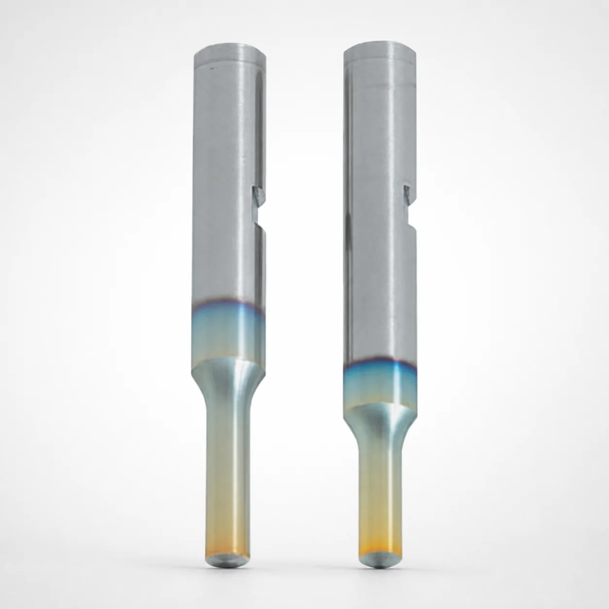
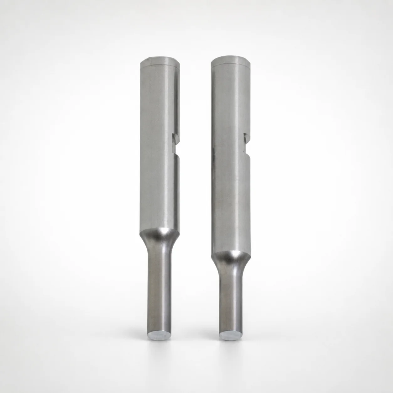
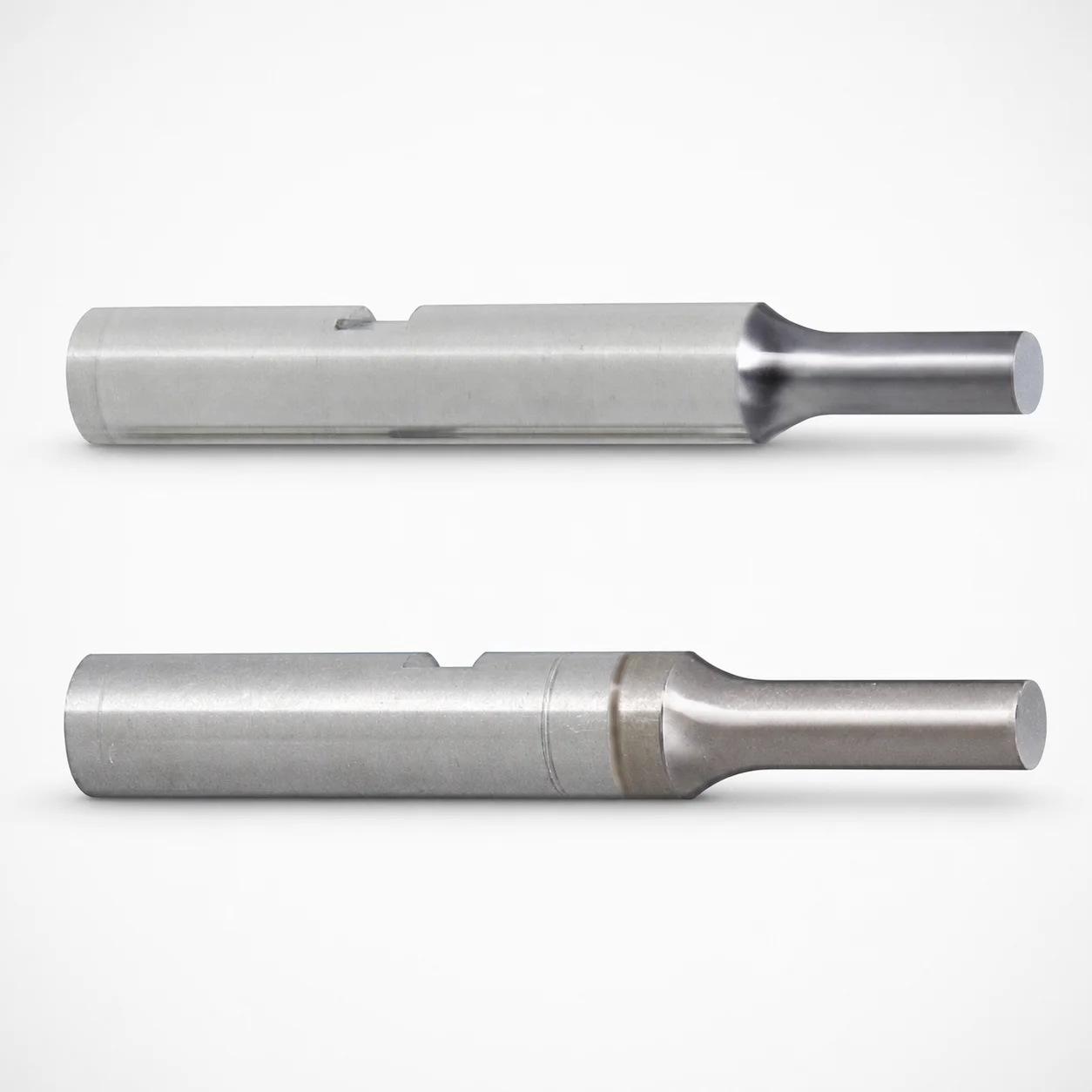
Punches with Key Grooves Single-Stepped Shank are designed for keyed punch mounting and stable guidance in tool and die assemblies. The built-in key groove helps maintain alignment during repeated press cycles, while coating options support wear resistance in demanding production.
- Single-stepped shank with key groove mounting for consistent positioning
- Coating options including WPC and HW coating for improved surface durability
- Hardened punch steel options for reliable performance in high-load operations
- Typical use in progressive dies and punching tools requiring keyed guidance
Specifications
8874 configurations available
| Tip shape | Material | Surface treatment | Shank diameter D tolerance | B (Tip length) | D (Shank diameter) (mm) | P (Tip dimension) (mm) | L (L dimension) (mm) | LC (Full length alteration) (mm) | LCT (Head thickness tolerance change + Total length alteration) (mm) | PC (Tip dimension alteration) (mm) | R (Tip corner R) (mm) | T (Key groove position) (mm) | W (Tip dimension) (mm) | WC (Tip dimension alteration) (mm) | type |
|---|---|---|---|---|---|---|---|---|---|---|---|---|---|---|---|
| A | Powdered high-speed steel | HW coating | +0.005/0 | L | 3 | 1 ~ 2.99 | 50 ~ 80 | - | - | - | - | 5.1 ~ 80 | - | - | - |
| A | Powdered high-speed steel | HW coating | +0.005/0 | L | 3 | - | 50 ~ 80 | - | - | 0.5 ~ 0.99 | - | 5.1 ~ 80 | - | - | - |
| A | Powdered high-speed steel | HW coating | +0.005/0 | L | 3 | 1 ~ 2.99 | - | 27 ~ 79.9 | - | - | - | 5.1 ~ 80 | - | - | - |
| A | Powdered high-speed steel | HW coating | +0.005/0 | L | 3 | - | - | 27 ~ 79.9 | - | 0.5 ~ 0.99 | - | 5.1 ~ 80 | - | - | - |
| A | Powdered high-speed steel | HW coating | +0.005/0 | L | 3 | 1 ~ 2.99 | - | - | 27 ~ 79.9 | - | - | 5.1 ~ 80 | - | - | - |
| A | Powdered high-speed steel | HW coating | +0.005/0 | L | 3 | - | - | - | 27 ~ 79.9 | 0.5 ~ 0.99 | - | 5.1 ~ 80 | - | - | - |
| A | Powdered high-speed steel | HW coating | +0.005/0 | L | 4 | 1 ~ 3.99 | 50 ~ 80 | - | - | - | - | 5.1 ~ 80 | - | - | - |
| A | Powdered high-speed steel | HW coating | +0.005/0 | L | 4 | - | 50 ~ 80 | - | - | 0.5 ~ 0.99 | - | 5.1 ~ 80 | - | - | - |
| A | Powdered high-speed steel | HW coating | +0.005/0 | L | 4 | 1 ~ 3.99 | - | 27 ~ 79.9 | - | - | - | 5.1 ~ 80 | - | - | - |
| A | Powdered high-speed steel | HW coating | +0.005/0 | L | 4 | - | - | 27 ~ 79.9 | - | 0.5 ~ 0.99 | - | 5.1 ~ 80 | - | - | - |
| A | Powdered high-speed steel | HW coating | +0.005/0 | L | 4 | 1 ~ 3.99 | - | - | 27 ~ 79.9 | - | - | 5.1 ~ 80 | - | - | - |
| A | Powdered high-speed steel | HW coating | +0.005/0 | L | 4 | - | - | - | 27 ~ 79.9 | 0.5 ~ 0.99 | - | 5.1 ~ 80 | - | - | - |
| A | Powdered high-speed steel | HW coating | +0.005/0 | L | 5 | 2 ~ 4.99 | 50 ~ 80 | - | - | - | - | 5.1 ~ 80 | - | - | - |
| A | Powdered high-speed steel | HW coating | +0.005/0 | L | 5 | - | 50 ~ 80 | - | - | 1 ~ 1.99 | - | 5.1 ~ 80 | - | - | - |
| A | Powdered high-speed steel | HW coating | +0.005/0 | L | 5 | 2 ~ 4.99 | - | 27 ~ 79.9 | - | - | - | 5.1 ~ 80 | - | - | - |
| A | Powdered high-speed steel | HW coating | +0.005/0 | L | 5 | - | - | 27 ~ 79.9 | - | 1 ~ 1.99 | - | 5.1 ~ 80 | - | - | - |
| A | Powdered high-speed steel | HW coating | +0.005/0 | L | 5 | 2 ~ 4.99 | - | - | 27 ~ 79.9 | - | - | 5.1 ~ 80 | - | - | - |
| A | Powdered high-speed steel | HW coating | +0.005/0 | L | 5 | - | - | - | 27 ~ 79.9 | 1 ~ 1.99 | - | 5.1 ~ 80 | - | - | - |
| A | Powdered high-speed steel | HW coating | +0.005/0 | L | 6 | 2 ~ 5.99 | 50 ~ 80 | - | - | - | - | 5.1 ~ 80 | - | - | - |
| A | Powdered high-speed steel | HW coating | +0.005/0 | L | 6 | - | 50 ~ 80 | - | - | 1 ~ 1.99 | - | 5.1 ~ 80 | - | - | - |
| A | Powdered high-speed steel | HW coating | +0.005/0 | L | 6 | 2 ~ 5.99 | - | 27 ~ 79.9 | - | - | - | 5.1 ~ 80 | - | - | - |
| A | Powdered high-speed steel | HW coating | +0.005/0 | L | 6 | - | - | 27 ~ 79.9 | - | 1 ~ 1.99 | - | 5.1 ~ 80 | - | - | - |
| A | Powdered high-speed steel | HW coating | +0.005/0 | L | 6 | 2 ~ 5.99 | - | - | 27 ~ 79.9 | - | - | 5.1 ~ 80 | - | - | - |
| A | Powdered high-speed steel | HW coating | +0.005/0 | L | 6 | - | - | - | 27 ~ 79.9 | 1 ~ 1.99 | - | 5.1 ~ 80 | - | - | - |
| A | Powdered high-speed steel | HW coating | +0.005/0 | L | 8 | 3 ~ 7.99 | 50 ~ 100 | - | - | - | - | 5.1 ~ 100 | - | - | - |
| A | Powdered high-speed steel | HW coating | +0.005/0 | L | 8 | - | 50 ~ 100 | - | - | 1.5 ~ 2.99 | - | 5.1 ~ 100 | - | - | - |
| A | Powdered high-speed steel | HW coating | +0.005/0 | L | 8 | 3 ~ 7.99 | - | 27 ~ 99.9 | - | - | - | 5.1 ~ 100 | - | - | - |
| A | Powdered high-speed steel | HW coating | +0.005/0 | L | 8 | - | - | 27 ~ 99.9 | - | 1.5 ~ 2.99 | - | 5.1 ~ 100 | - | - | - |
| A | Powdered high-speed steel | HW coating | +0.005/0 | L | 8 | 3 ~ 7.99 | - | - | 27 ~ 99.9 | - | - | 5.1 ~ 100 | - | - | - |
| A | Powdered high-speed steel | HW coating | +0.005/0 | L | 8 | - | - | - | 27 ~ 99.9 | 1.5 ~ 2.99 | - | 5.1 ~ 100 | - | - | - |
| A | Powdered high-speed steel | HW coating | +0.005/0 | L | 10 | 3 ~ 9.99 | 50 ~ 100 | - | - | - | - | 5.1 ~ 100 | - | - | - |
| A | Powdered high-speed steel | HW coating | +0.005/0 | L | 10 | - | 50 ~ 100 | - | - | 1.5 ~ 2.99 | - | 5.1 ~ 100 | - | - | - |
| A | Powdered high-speed steel | HW coating | +0.005/0 | L | 10 | 3 ~ 9.99 | - | 27 ~ 99.9 | - | - | - | 5.1 ~ 100 | - | - | - |
| A | Powdered high-speed steel | HW coating | +0.005/0 | L | 10 | - | - | 27 ~ 99.9 | - | 1.5 ~ 2.99 | - | 5.1 ~ 100 | - | - | - |
| A | Powdered high-speed steel | HW coating | +0.005/0 | L | 10 | 3 ~ 9.99 | - | - | 27 ~ 99.9 | - | - | 5.1 ~ 100 | - | - | - |
| A | Powdered high-speed steel | HW coating | +0.005/0 | L | 10 | - | - | - | 27 ~ 99.9 | 1.5 ~ 2.99 | - | 5.1 ~ 100 | - | - | - |
| A | Powdered high-speed steel | HW coating | +0.005/0 | L | 13 | 6 ~ 12.99 | 50 ~ 100 | - | - | - | - | 5.1 ~ 100 | - | - | - |
| A | Powdered high-speed steel | HW coating | +0.005/0 | L | 13 | - | 50 ~ 100 | - | - | 3 ~ 5.99 | - | 5.1 ~ 100 | - | - | - |
| A | Powdered high-speed steel | HW coating | +0.005/0 | L | 13 | 6 ~ 12.99 | - | 27 ~ 99.9 | - | - | - | 5.1 ~ 100 | - | - | - |
| A | Powdered high-speed steel | HW coating | +0.005/0 | L | 13 | - | - | 27 ~ 99.9 | - | 3 ~ 5.99 | - | 5.1 ~ 100 | - | - | - |
| A | Powdered high-speed steel | HW coating | +0.005/0 | L | 13 | 6 ~ 12.99 | - | - | 27 ~ 99.9 | - | - | 5.1 ~ 100 | - | - | - |
| A | Powdered high-speed steel | HW coating | +0.005/0 | L | 13 | - | - | - | 27 ~ 99.9 | 3 ~ 5.99 | - | 5.1 ~ 100 | - | - | - |
| A | Powdered high-speed steel | HW coating | +0.005/0 | L | 16 | 10 ~ 15.99 | 60 ~ 100 | - | - | - | - | 5.1 ~ 100 | - | - | - |
| A | Powdered high-speed steel | HW coating | +0.005/0 | L | 16 | - | 60 ~ 100 | - | - | 5 ~ 9.99 | - | 5.1 ~ 100 | - | - | - |
| A | Powdered high-speed steel | HW coating | +0.005/0 | L | 16 | 10 ~ 15.99 | - | 27 ~ 99.9 | - | - | - | 5.1 ~ 100 | - | - | - |
| A | Powdered high-speed steel | HW coating | +0.005/0 | L | 16 | - | - | 27 ~ 99.9 | - | 5 ~ 9.99 | - | 5.1 ~ 100 | - | - | - |
| A | Powdered high-speed steel | HW coating | +0.005/0 | L | 16 | 10 ~ 15.99 | - | - | 27 ~ 99.9 | - | - | 5.1 ~ 100 | - | - | - |
| A | Powdered high-speed steel | HW coating | +0.005/0 | L | 16 | - | - | - | 27 ~ 99.9 | 5 ~ 9.99 | - | 5.1 ~ 100 | - | - | - |
| A | Powdered high-speed steel | HW coating | +0.005/0 | S | 3 | 1 ~ 2.99 | 40 ~ 80 | - | - | - | - | 5.1 ~ 80 | - | - | - |
| A | Powdered high-speed steel | HW coating | +0.005/0 | S | 3 | - | 40 ~ 80 | - | - | 0.5 ~ 0.99 | - | 5.1 ~ 80 | - | - | - |
Product Guide
Application Scenarios+
Key-groove punches with a single-stepped shank are used to provide positive keyed mounting and repeatable alignment inside punch and die sets. The built-in groove maintains orientation through frequent press cycles, which reduces risk of hole position shift in high-volume forming lines.
- Automotive and electronics progressive dies: When producing stamped features that require tight pitch control, the keyed shank helps keep the punch working axis consistent across many stations; select powdered high-speed steel or SKH51 for higher wear performance.
- Appliance and metal fabrication tooling: In tools running at elevated contact loads, the stepped shank supports stable guidance, while WPC or HW coating options improve surface durability against abrasion.
- Multi-cavity layout tools: For interchangeable punch stations, dimensional consistency and the specified shank diameter with m5 tolerance ( +0.005/0 ) supports dependable fit into locating bushings or retainer blocks.
Choose this variant when keyed positioning and wear-resistant surfaces are critical to dimensional stability.
Material & Process Details+
This punch family is offered in powdered high-speed steel, SKH51, and SKD11 equivalent grades, supporting different toughness-to-wear trade-offs for punching applications. SKH51 is a high-performance high-speed steel typically aligned with AISI M2 in performance class, favoring wear resistance for edge-intensive operations.
- Powdered HSS: Generally provides excellent uniform carbide distribution, supporting strong wear resistance under cyclic loading.
- SKD11 equivalent: A tool steel commonly selected where higher toughness and shock resistance are needed; it may show a different wear/toughness balance compared with high-speed steels.
Surface treatment options include HW coating and WPC to improve abrasion and reduce galling at the punch-workpiece interface. While the exact target hardness and heat-treatment cycle are not specified in the provided data, these grades are typically supplied in a hardened condition appropriate for punch tooling, with the selected coating further boosting wear performance.
Sizing & Selection Guide+
To select the correct keyed single-stepped punch, match the shank diameter D and overall geometry to the locating features in your punch holder or retainer. The shank diameter range is 3 ~ 16 mm, with a specified tolerance of +0.005/0 and m5 fit condition—ensure your holder/bushing bore is designed to accept this class for stable guidance without excessive play.
- Tip and corner geometry: Confirm tip dimension P (1 ~ 10 mm), W (1 ~ 5 mm), and corner radius R (0.15 mm). Select tip shape from A, D, E, G, R to match your cutting profile.
- Lengths: Choose B (tip length) from L, S, X and set the L (40 ~ 70 mm) and LC (27 ~ 79.9 / 99.9) (as your assembly requires).
- Key groove position: The key groove position T is specified across ranges (e.g., 5.1 ~ 80, 5.1 ~ 100), so align T to your keyed mounting feature.
When ordering variant configurations, use the provided alteration parameters (e.g., PC 0.5 ~ 5, WC 0.8 ~ 2) to maintain stack-up consistency across stations.
Frequently Asked Questions
Which steel option is best for high-wear punching: powdered HSS, SKH51, or SKD11 equivalent?+
What shank diameter tolerance applies to this keyed punch, and how should it be fitted in the punch holder?+
How do I select the key groove position (T) so the punch seats correctly?+
What coating options are available and what are they intended to improve in punching tools?+
How should I match tip geometry (shape, P/W, and corner radius R) to the die opening design?+
Related Products
Need Custom Specifications?
Our engineering team can help with custom configurations, material selection, and volume pricing.