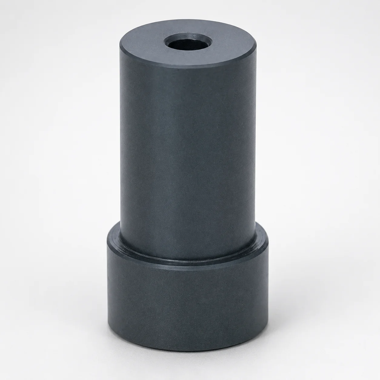
Type SPLF Stepped Support Pillars - Counterbore
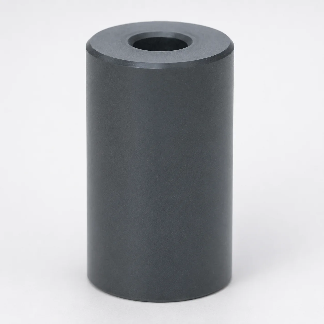
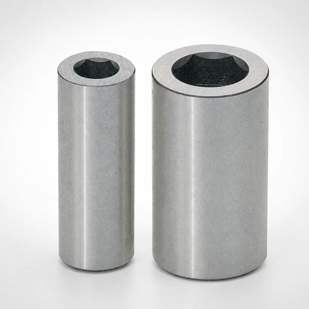
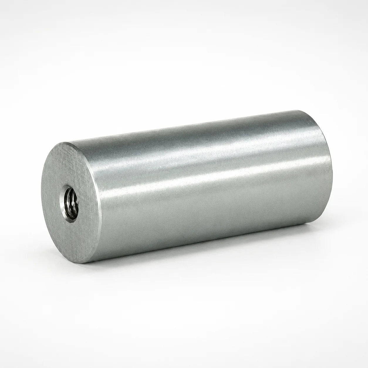
Type SPLF Stepped Support Pillars - Counterbore provide reliable stability through a stepped profile that improves load-bearing capacity while maintaining precise alignment for assemblies. The counterbore design helps seat and locate mating hardware cleanly during installation.
- Stepped support geometry improves load distribution and alignment stability
- Counterbore feature supports accurate seating and consistent fit
- Type SPLF configuration is optimized for dependable positioning in use
- Suitable for machine supports, structural fixtures, and industrial assembly applications
Specifications
6 configurations available
| D (Shaft diameter) (mm) | L (L dimension) (mm) | F (Stepped section diameter) (mm) | T (Stepped section length) (mm) | type |
|---|---|---|---|---|
| 20 | 45 ~ 150 | 25 ~ 30 | 10 ~ 45 | - |
| 25 | 45 ~ 150 | 30 ~ 35 | 10 ~ 45 | - |
| 30 | 50 ~ 200 | 35 ~ 40 | 10 ~ 45 | - |
| 35 | 50 ~ 250 | 40 ~ 50 | 10 ~ 45 | - |
| 40 | 50 ~ 250 | 45 ~ 55 | 10 ~ 45 | - |
| 50 | 50 ~ 300 | 55 ~ 65 | 10 ~ 45 | - |
Product Guide
Application Scenarios+
Type SPLF stepped support pillars with counterbore are used in injection mold tooling where you need stable, repeatable support and accurate positioning of mating parts. The stepped profile improves load distribution, helping maintain alignment under clamping and cyclic operating forces.
- Automotive and appliance housing molds: In leader-ejector-space regions, these pillars support machine or structural components and maintain consistent alignment to reduce localized stress and parting-line variation.
- Medical device and precision enclosure molds: The counterbore helps seat and locate mating hardware cleanly during assembly, improving repeatability when swapping inserts, carriers, or support plates.
- Industrial fixtures and assembly tooling: Use where stepped load transfer and robust guidance are required to keep components positioned through frequent maintenance.
With selectable shaft diameters (D = 20–50 mm) and stepped section dimensions, this variant matches common mold bases and supports requiring reliable guidance without sacrificing positional accuracy.
Material & Process Details+
The provided specifications for this product focus on geometry (D, L, stepped section dimensions, and counterbore concept), but no steel grade, hardness, or heat treatment state is listed in the input data. As a result, the exact material properties (e.g., specific steel grade such as SKD61/H13-equivalent, or hardness in HRC) cannot be stated without additional product documentation.
For stepped support pillars, material choice typically balances wear resistance (surface durability against contact/friction), and toughness (resistance to bending or impact during installation and shut-down cycles). In general industrial mold designs, steels are often provided in either pre-hardened form or via quench-and-temper prior to machining, then finished to required tolerances.
- Key note: Confirm the exact steel grade and heat treatment with Axiom Molds for hardness verification.
- Variant comparison: If multiple material options exist, compare based on required toughness vs. stiffness and expected contact load at the counterbore interface.
Sizing & Selection Guide+
Select the stepped support pillar dimensions to match the mold base/core interface requirements and the guidance/loading conditions in the leader-ejector-space area. The shaft diameter (D) is available in 20, 25, 30, 35, 40, and 50 mm; choose the diameter that fits the mating bore or guide pocket in your mold layout.
- Choose length (L): L is offered in ranges of 45–150 mm, 50–200 mm, 50–250 mm, and 50–300 mm. Ensure the pillar length spans the required engagement depth while accounting for hardware height above the seating surface.
- Match stepped geometry: The stepped section diameter (F) is offered across 25–30, 30–35, 35–40, 40–50, 45–55, and 55–65 mm. The stepped section length (T) is 10–45 mm; align T with the supported contact zone in the cavity/core or fixture.
When using the counterbore function, verify that the mating hardware’s seating diameter and stack-up height correspond to the stepped shoulder and counterbore depth to maintain consistent fit and alignment. If your mold uses close-fit guidance, confirm allowable clearance/tolerance for the chosen D and stepped diameters with your designer standards.
Frequently Asked Questions
How do I select the shaft diameter (D) for SPLF stepped support pillars in a mold base leader-ejector-space layout?+
What L (length) range should I choose to ensure sufficient engagement without bottoming out?+
How should the stepped section diameter (F) and stepped length (T) be matched to the supported contact area?+
Does the counterbore feature require specific seating dimensions for reliable alignment?+
What material grade and hardness (HRC) should I expect for this SPLF counterbore stepped support pillar?+
Related Products
Need Custom Specifications?
Our engineering team can help with custom configurations, material selection, and volume pricing.