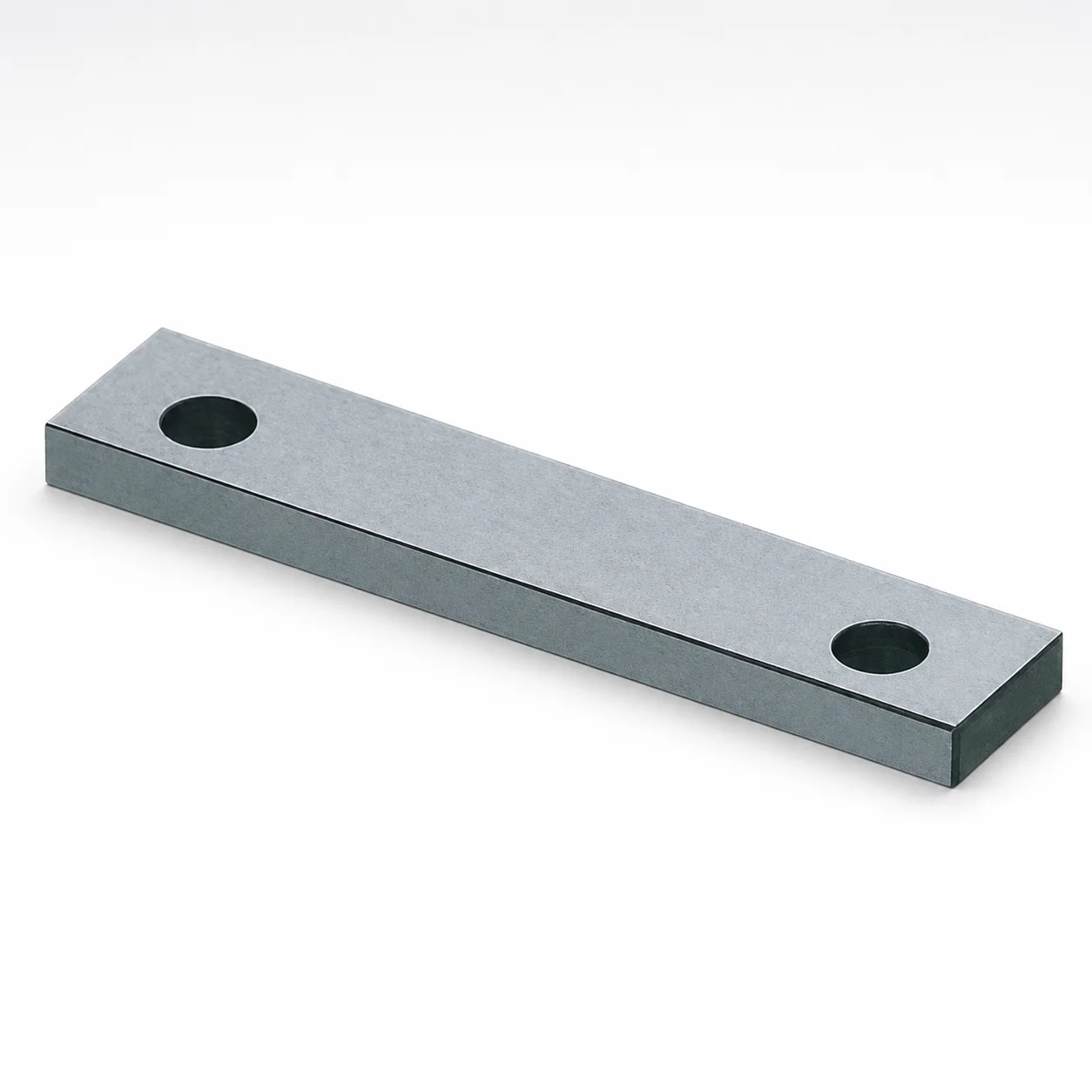
Plate Guide Rails for Tool Steels
Plate Guide Rails for Tool Steels provide reliable linear motion support for precise movement of guided components. The rail design improves alignment and stability while reducing friction and wear in demanding industrial builds.
- Stable guide rail structure supports accurate component positioning
- Low-friction contact design helps minimize wear during operation
- Durable tool-steel rail construction for long service life
- Used in automation and machinery tooling requiring smooth linear motion
Specifications
4 configurations available
| Type | W (Width) (mm) | A (Bolt hole pitch) (mm) | B (Bolt hole pitch) (mm) | L (L dimension) (mm) | type |
|---|---|---|---|---|---|
| Standard | 10 | 6 ~ 44 | 16 ~ 54 | 25 ~ 60 | - |
| Standard | 15 | 7.5 ~ 59.5 | 20.5 ~ 72.5 | 30 ~ 80 | - |
| Standard | 20 | 7.5 ~ 79.5 | 20.5 ~ 92.5 | 30 ~ 100 | - |
| Thin | 10 | 6 ~ 44 | 16 ~ 54 | 25 ~ 60 | - |
Product Guide
Application Scenarios+
These plate guide rails are used in injection mold tooling and automation frames to provide stable linear motion for guided plates, ejector/leader systems, and motion-coupled components that must maintain alignment under repeated cycling.
- Automotive connector and housing molds: Employ rails of Standard or Thin type to support smooth, low-deflection movement of guided parts, helping keep shutoff and alignment consistent during high-volume operation.
- Medical device mold assemblies: Use the low-friction rail contact to reduce stick-slip and maintain positional repeatability, which is important for consistent cavity-side part formation and reduced scrap risk.
- Packaging and appliance tooling automation: In long-stroke guided mechanisms, the defined bolt-hole pitch and width options enable rigid mounting, supporting stable travel with reduced wear.
The rail variant is suited because its steel-rail style construction and dimensional options (width W and bolt-hole pitches) allow engineers to tune stiffness and mounting rigidity for a given guided stroke and plate layout.
Material & Process Details+
The provided product metadata specifies dimensions and mounting geometry, but does not include a specific steel grade or heat-treatment state. As a result, hardness (HRC), nitriding/carburizing details, and exact wear/toughness trade-offs cannot be stated from the given data.
For “tool-steel” leader/guide rail applications, suppliers typically select a wear-resistant tool steel and apply quench-and-temper or similar hardening to balance surface wear resistance with adequate toughness to resist chipping under impact and repeated cycling.
- Wear resistance vs. toughness: Harder conditions generally improve scuffing and abrasion resistance but can reduce toughness if the tempering is insufficient.
- Thin vs. Standard type: Thinner rails are often selected where envelope limits exist, but engineers should verify that stiffness meets deflection and alignment requirements.
If you share the exact steel grade or heat-treatment spec used for this part number, material hardness and the appropriate comparison between alternatives can be documented precisely.
Sizing & Selection Guide+
Select the rail by matching its mounting geometry to the guided plate and mold base layout. Use the provided dimensions:
- Type: choose Standard for general stiffness needs or Thin when space constraints limit rail thickness (type is a configurable variant in this series).
- Width W (mm): 10, 15, or 20—pick the width that fits the available rail seat and provides the required contact area.
- Bolt-hole pitch ranges (mm): A (6 ~ 44, 7.5 ~ 59.5, 7.5 ~ 79.5) and B (16 ~ 54, 20.5 ~ 72.5, 20.5 ~ 92.5)—choose the variant whose pitch matches your plate hole spacing within the stated range.
- Length L (mm): 25 ~ 60, 30 ~ 80, 30 ~ 100—select based on the required guided travel and effective support length.
Because the input data provides pitch ranges rather than exact fixed values, use your drawing’s hole spacing to choose the correct sub-variant. Tolerance and fit (clearance for low friction and alignment) must be confirmed against the rail-to-plate guidance design; the given metadata does not specify tolerances, so verify them in the manufacturer’s technical drawings for the selected SKU.
Frequently Asked Questions
How do I choose between the Standard and Thin types for a leader-ejector guide application?+
Use Standard when you need maximum structural stiffness for stable alignment over the stroke. Choose Thin when the mold or automation envelope limits rail thickness, but still verify that the mounting stiffness and effective support length (L range) meet deflection requirements.
The available options for width (W = 10/15/20 mm) and length (L = 25–60, 30–80, 30–100 mm) help you compensate by selecting appropriate mounting coverage.
What bolt-hole pitch values should I match when mounting the rail to my guided plate?+
The rail provides mounting geometry via A (6–44, 7.5–59.5, 7.5–79.5 mm) and B (16–54, 20.5–72.5, 20.5–92.5 mm). Match your guided-plate hole spacing to the corresponding pitch in the stated range.
Because the data is range-based, you should confirm the exact pitch and hole count in the drawing for the selected SKU, then verify any clearance to your fasteners and dowel/locating strategy.
Which rail width (W) is appropriate for maintaining alignment in long-running tooling?+
Select W = 10, 15, or 20 mm based on the available rail seat and the required guidance surface width. Wider rails typically provide more contact area and can improve resistance to localized wear and misalignment caused by plate deflection.
For long strokes, also choose an appropriate L (25–60 / 30–80 / 30–100 mm) to maintain adequate support length over the travel.
How should I select L (length) to cover the full guided stroke without overhang issues?+
Use the provided L ranges (25–60, 30–80, 30–100 mm) to cover the required guided travel with sufficient overlap/support at the stroke extremes.
If your mechanism includes end-of-stroke stop regions or transitions, ensure the effective support length keeps the guided component supported throughout the motion. The metadata does not specify overhang limits, so validate against your assembly’s kinematics and rail-to-plate clearance design.
Is this rail suitable for low-friction operation, and what dimensional checks should I perform?+
The product description emphasizes stable, low-friction linear motion to reduce wear and maintain alignment. Perform dimensional checks using W (10/15/20 mm), A and B pitch ranges, and L to ensure your mounting pattern supports rigid alignment.
Since no tolerances are provided in the metadata, confirm the rail fit/clearance and any required mounting tolerances in the manufacturer’s detailed specification for the exact SKU.
Related Products
Need Custom Specifications?
Our engineering team can help with custom configurations, material selection, and volume pricing.