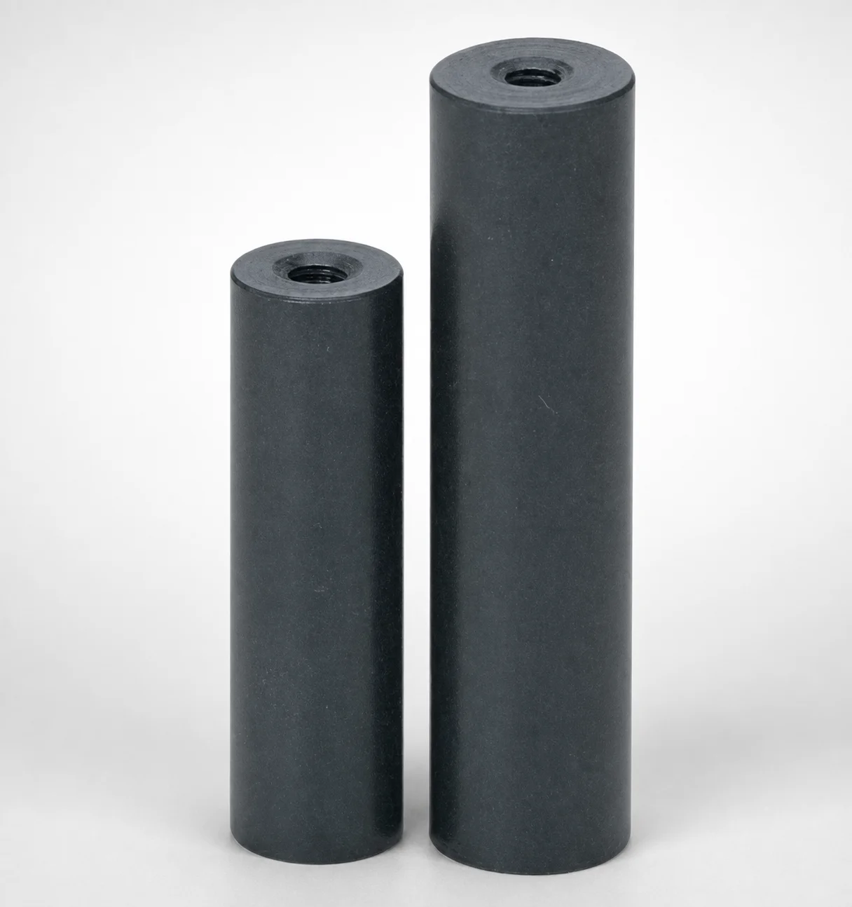
SPL Tapped Support Pillars
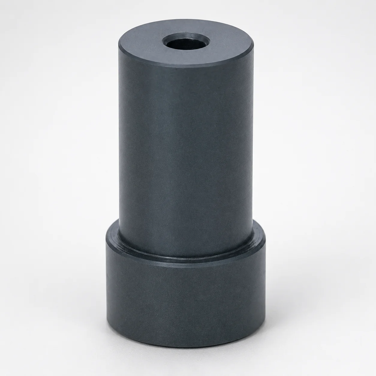
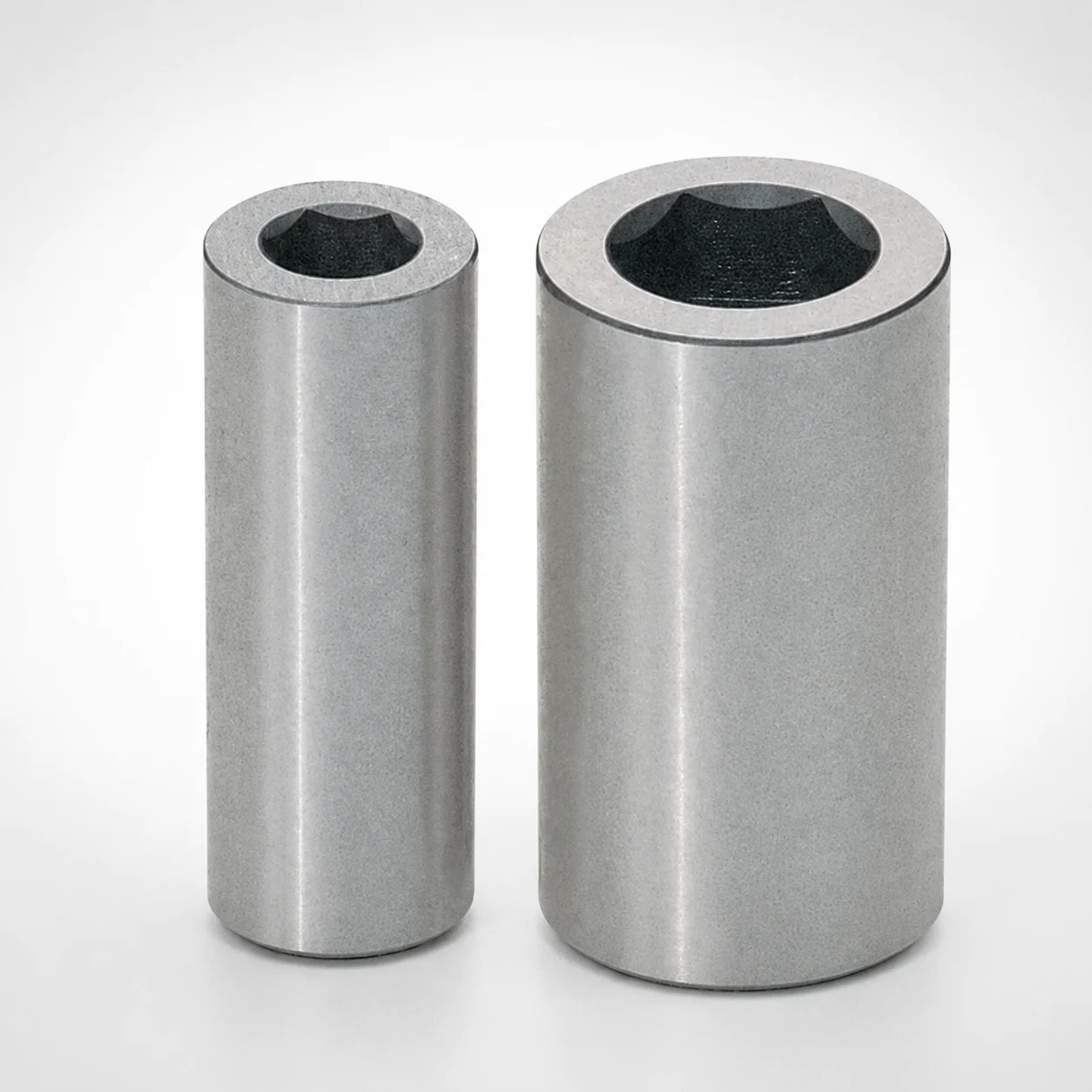
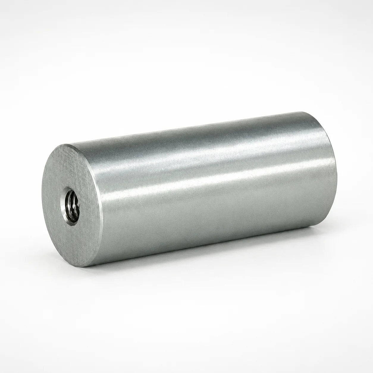
SPL tapped support pillars provide secure, threaded mounting to stabilize industrial fixtures and machinery assemblies. Their robust design helps maintain alignment while absorbing vibration and load during operation.
- Threaded SPL support pillar design for dependable fixture retention
- Engineered for vibration and load absorption without compromising alignment
- Consistent dimensional performance supports repeatable installation and positioning
- Used in machinery setups, structural support frames, and automation fixtures
Specifications
59 configurations available
| D (Shaft diameter) (mm) | Alterations | L (L dimension) (mm) | LC (L dimension alteration) (mm) | type |
|---|---|---|---|---|
| 12 | Yes | 40 ~ 55 | - | - |
| 12 | Yes | 60 ~ 100 | - | - |
| 12 | Yes | - | 20 ~ 99 | - |
| 14 | Yes | 40 ~ 55 | - | - |
| 14 | Yes | 60 ~ 120 | - | - |
| 14 | Yes | - | 20 ~ 119 | - |
| 16 | Yes | 40 ~ 55 | - | - |
| 16 | Yes | 60 ~ 120 | - | - |
| 16 | Yes | - | 20 ~ 119 | - |
| 18 | Yes | 40 ~ 55 | - | - |
| 18 | Yes | 60 ~ 120 | - | - |
| 18 | Yes | - | 20 ~ 119 | - |
| 20 | Yes | 45 ~ 55 | - | - |
| 20 | Yes | 60 ~ 150 | - | - |
| 20 | Yes | - | 20 ~ 149 | - |
| 25 | No | 45 | - | - |
| 25 | No | 50 | - | - |
| 25 | No | 60 | - | - |
| 25 | No | 70 | - | - |
| 25 | No | 80 | - | - |
| 25 | No | 90 | - | - |
| 25 | No | 100 | - | - |
| 25 | Yes | 45 ~ 55 | - | - |
| 25 | Yes | 60 ~ 150 | - | - |
| 25 | Yes | - | 20 ~ 149 | - |
| 30 | No | 80 | - | - |
| 30 | Yes | 50 ~ 300 | - | - |
| 30 | Yes | - | 40 ~ 299 | - |
| 32 | Yes | 50 ~ 300 | - | - |
| 32 | Yes | - | 40 ~ 299 | - |
| 35 | No | 80 | - | - |
| 35 | Yes | 50 ~ 300 | - | - |
| 35 | Yes | - | 40 ~ 299 | - |
| 40 | No | 70 | - | - |
| 40 | No | 90 | - | - |
| 40 | No | 100 | - | - |
| 40 | No | 110 | - | - |
| 40 | No | 120 | - | - |
| 40 | Yes | 50 ~ 300 | - | - |
| 40 | Yes | - | 40 ~ 299 | - |
| 45 | Yes | 50 ~ 200 | - | - |
| 45 | Yes | - | 40 ~ 199 | - |
| 50 | No | 80 | - | - |
| 50 | No | 90 | - | - |
| 50 | No | 100 | - | - |
| 50 | No | 130 | - | - |
| 50 | No | 140 | - | - |
| 50 | Yes | 50 ~ 400 | - | - |
| 50 | Yes | - | 40 ~ 399 | - |
| 55 | Yes | 50 ~ 200 | - | - |
Product Guide
Application Scenarios+
SPL tapped support pillars are used in injection mold tooling wherever a stable, rigid fixture interface is required—especially in leader/ejector space areas and automation-adjacent assemblies. Scenario 1: automation fixture alignment—the threaded mounting supports consistent positioning of sensor brackets, cable carriers, or part-handling accessories, helping resist shift under repeated cycling.
- Vibration and load control: the robust pillar body is intended to maintain alignment while absorbing operational vibration and assembly loads.
- Scenario 2: machinery structural support frames—secure threads allow reliable retention during installation and maintenance, improving repeatability when fixtures are removed and reinstalled.
Scenario 3: industrial equipment housings and alignment platforms—use the correct shaft diameter and length to match the required stance and stack height. The availability of dimensional alterations supports customization to the mold base thickness or fixture stand-off requirements.
Material & Process Details+
The provided datasheet for this product focuses on dimensional compatibility (shaft diameter and lengths) and does not specify a steel grade, heat treatment condition, hardness (HRC), or surface treatment. As a result, material-property claims such as wear resistance, toughness trade-offs, or nitriding/carburizing response cannot be stated from the input data.
- What can be confirmed: this is a tapped support pillar concept designed for secure threaded mounting and stable alignment under vibration and load.
- What to verify: request the specific material grade and heat treatment state (e.g., pre-hardened vs. quenched & tempered, nitrided) from the manufacturer/part datasheet if your application requires quantified wear resistance or impact toughness.
- Multiple options: if MISUMI offers material variants, select based on your expected cutting/loading environment and desired hardness level.
Sizing & Selection Guide+
Select dimensions to match the fixture’s mounting height, clearance, and load path. The key parameters for this series are D (shaft diameter) = 12 ~ 120 mm and L (length) = 40 ~ 140 mm, with an additional LC alteration range = 20 ~ 60 mm.
- Match D to hardware and mounting features: choose the shaft diameter that aligns with the threaded hole/bore standard used in your tooling or fixture plate.
- Match L to required stand-off: L should set the installed height so the fixture interface reaches the target plane without bottoming out or excessive thread engagement loss.
- Use LC alterations when stack height varies: apply the available LC alteration capability to compensate for changes in base thickness, spacers, or wear/adjustment provisions.
Tolerance/fit: because exact tolerance values are not included in the provided specifications, confirm the recommended thread engagement/fit and allowable clearance for your plate or support interface before final design freeze.
Frequently Asked Questions
Which dimensions (D, L, LC) control how securely the SPL tapped support pillar mounts in a leader/ejector space fixture?+
The SPL tapped support pillar’s mechanical compatibility is primarily determined by D (shaft diameter) = 12 ~ 120 mm and L (length) = 40 ~ 140 mm. Use LC (L dimension alteration) = 20 ~ 60 mm when you need to adjust effective mounting height for your base thickness or stand-off requirements. Confirm thread engagement and interface clearances for your specific fixture plate, since tolerances are not provided in the input data.
Can I order dimensional alterations for this series, and what ranges are available?+
The product data indicates Alterations: Yes. The alteration-relevant range provided is LC = 20 ~ 60 mm, while the core ranges remain D = 12 ~ 120 mm and L = 40 ~ 140 mm. Select altered values only after verifying the required installed height and safe thread engagement in your tooling interface.
How should I choose shaft diameter D to avoid fixture misalignment under vibration?+
Choose D within 12 ~ 120 mm to match the threaded mounting interface of your fixture plate or support frame. A correct D ensures proper thread engagement and reduces the risk of micro-movement that can lead to alignment drift during cycling. Since hardness and material grade are not specified in the input data, alignment stability under wear should be validated with the exact material/heat treatment from the datasheet.
What L length range should I use for a target stand-off height in the mold tooling stack?+
Use L within 40 ~ 140 mm so the installed pillar height positions the fixture interface at the required plane. If your mold base thickness or spacer stack changes, use LC = 20 ~ 60 mm to fine-tune the effective dimension. Because tolerance values are not included, confirm your clearance and bottoming limits for the assembled stack-up.
What material/heat treatment should I specify for high-load or high-wear industrial equipment applications?+
The supplied information does not list a steel grade, hardness (HRC), or heat treatment state for this series. For high-load/high-wear use, request the exact material specification and the heat treatment condition (e.g., quenched & tempered, nitrided) from MISUMI so you can evaluate wear resistance and toughness trade-offs. Once the material details are confirmed, select dimensions (D and L) that ensure adequate thread engagement and mechanical stiffness.
Related Products
Need Custom Specifications?
Our engineering team can help with custom configurations, material selection, and volume pricing.