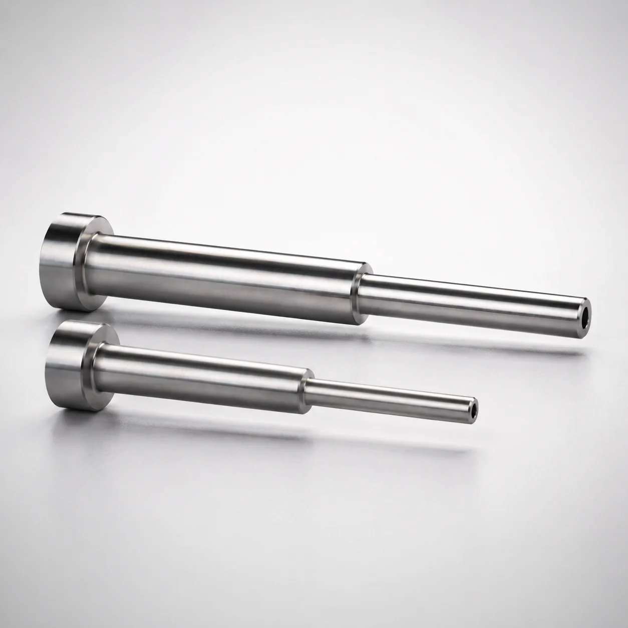
Japanese Standard SKD61 Steel Stepped Ejector Sleeves
Stepped ejector sleeves (SKD61 steel) with a nitrided surface treatment are engineered for stable fit in tooling systems. The stepped sleeve geometry supports reliable alignment during ejector operation, with single-sleeve construction for straightforward installation.
- Stepped sleeve design for consistent alignment in ejector tooling
- SKD61 steel with nitrided surface for wear resistance
- Controlled bores with H7 inner-diameter tolerance for dependable fit
- Used with single sleeve assemblies in precision die and mold builds
Specifications
8 configurations available
| Head Thickness | D (Shaft Diameter) (mm) | P (Tip Diameter) (mm) | V (Hole Diameter) (mm) | L (L dimension) (mm) | Dimension N (mm) | type |
|---|---|---|---|---|---|---|
| 8mm(JIS) | 8 | - | 3 ~ 4.5 | 125 ~ 250 | 50 ~ 120 | - |
| 8mm(JIS) | 12 | - | 5 ~ 5.5 | 150 ~ 300 | 60 ~ 120 | - |
| 8mm(JIS) | 15 | - | 6 ~ 9 | 200 ~ 300 | 80 ~ 150 | - |
| 8mm(JIS) | 20 | - | 11 ~ 15 | 200 ~ 300 | 80 ~ 150 | - |
| 4mm(T4) | 4 | 3 ~ 3.5 | 1.5 ~ 2 | 125 | 50 ~ 80 | - |
| 4mm(T4) | 5 | 3.5 ~ 4 | 2 ~ 2.5 | 125 | 50 ~ 80 | - |
| 4mm(T4) | 6 | 4 ~ 5 | 2 ~ 3.5 | 150 ~ 250 | 60 ~ 100 | - |
| 4mm(T4) | 8 | 4 ~ 6.5 | 2.5 ~ 3.5 | 100 ~ 250 | 60 ~ 100 | - |
Product Guide
Application Scenarios+
Stepped ejector sleeves are used in injection mold tooling wherever precise ejector alignment is critical to prevent rubbing, mis-travel, or uneven ejection. This SKD61-based, nitrided variant is designed to maintain dimensional stability at the sliding interface while supporting a controlled stepped geometry that helps guide the ejector motion.
- Automotive connector and housing molds: In multi-cavity builds with frequent cycle duty, the stepped sleeve geometry improves concentricity and alignment, helping the ejector system return consistently after ejection.
- Consumer product tooling with high repeatability requirements: The H7 inner-diameter fit supports stable assembly positioning and reduces clearance-related wear during frequent ejector strokes.
- Precision die and mold assemblies (single-sleeve configuration): The single-sleeve design supports straightforward installation and consistent guidance in compact ejector layouts.
Choose this variant when you need wear-resistant sliding performance plus stable fit (H7) to protect ejector components under repeated movement.
Material & Process Details+
Steel grade: SKD61 is a Japanese standard hot-work tool steel widely used for mold components requiring good heat resistance and toughness. It is commonly compared to AISI H13 in terms of application class (hot-work tooling performance).
Surface treatment: A nitrided surface is specified for improved wear resistance at the sliding interface. Nitriding increases surface hardness and abrasion resistance while keeping the core more tolerant to impact and bending stresses.
- Hardness: Exact HRC is not provided in the supplied data; hardness performance should be validated to your assembly’s contact pressure and duty cycle.
- Wear vs. toughness trade-off: The nitrided layer improves wear resistance, while the SKD61 core provides toughness for reliable ejector operation.
- Manufacturing relevance: Typical workflow includes machining of the stepped bore/shaft features, followed by nitriding to strengthen the contact surface.
If you need higher impact toughness than a nitrided surface provides, consider a non-nitrided SKD61 variant; if you need maximum sliding wear performance, nitriding is the key differentiator.
Sizing & Selection Guide+
Select the stepped ejector sleeve by matching both the shaft diameter (D) and the tip/hole related dimensions to your ejector and guidance requirements, then verify the fit class for the inner bore.
- Shaft diameter, D: Available in 4 ~ 20 mm. Match D to the ejector/shaft diameter that interfaces with the sleeve.
- Tip diameter, P: Choose the correct step feature from 3 ~ 3.5, 3.5 ~ 4, 4 ~ 5, or 4 ~ 6.5 mm based on your ejector tip geometry.
- Hole diameter, V: Available 1.5 ~ 11 mm. Confirm this aligns with the locating or functional bore requirement in your assembly.
- Length options (L) and N dimension: L is offered across multiple ranges such as 125 ~ 250, 150 ~ 300, 200 ~ 300, 125, 150 ~ 250, and 100 ~ 250; N is offered as 50 ~ 120, 60 ~ 120, 80 ~ 150, 50 ~ 80, or 60 ~ 100.
This variant supports a H7 fit inner-diameter tolerance, so select the bore size to achieve the intended sliding clearance with your mating ejector parts. Use your mold assembly drawing to confirm overall reach using L and the step/interface location using N, since these dimensions govern guidance engagement.
Frequently Asked Questions
Which shaft diameter (D) range is supported, and how do I ensure the sleeve matches my ejector shaft?+
The shaft diameter D is specified in the range 4 ~ 20 mm. Select the sleeve variant whose D matches your ejector shaft diameter to ensure proper guidance and avoid excessive clearance or interference during ejection.
What fit is provided for the inner bore, and why does this matter for ejector alignment?+
This stepped ejector sleeve is designed with a H7 inner-diameter tolerance. A controlled H7 fit helps maintain stable concentricity and assembly positioning, reducing misalignment-induced rubbing and uneven wear in repeated ejector strokes.
How do I choose the correct stepped geometry using P and V dimensions?+
Choose P based on the required tip diameter step: 3 ~ 3.5, 3.5 ~ 4, 4 ~ 5, or 4 ~ 6.5 mm. Then confirm the hole diameter V falls within 1.5 ~ 11 mm to match the functional bore/locating requirement in your ejector system.
Is the nitrided surface intended for wear resistance, and what lubrication/clearance behavior should I expect?+
The product uses an SKD61 steel base with a nitrided surface to improve wear resistance at the sliding interface. While exact HRC values are not provided, nitriding generally increases abrasion resistance, which helps reduce wear under frequent ejector movement. Validate clearance and contact pressure with your specific mold design.
How should I select length (L) and the N dimension to match cavity/core stack-up?+
Use L to ensure the sleeve reach matches the ejector stroke and the guidance engagement length; available ranges include 125 ~ 250, 150 ~ 300, 200 ~ 300, 125, 150 ~ 250, and 100 ~ 250. Use N to position the stepped interface correctly; available ranges include 50 ~ 120, 60 ~ 120, 80 ~ 150, 50 ~ 80, and 60 ~ 100.
Related Products
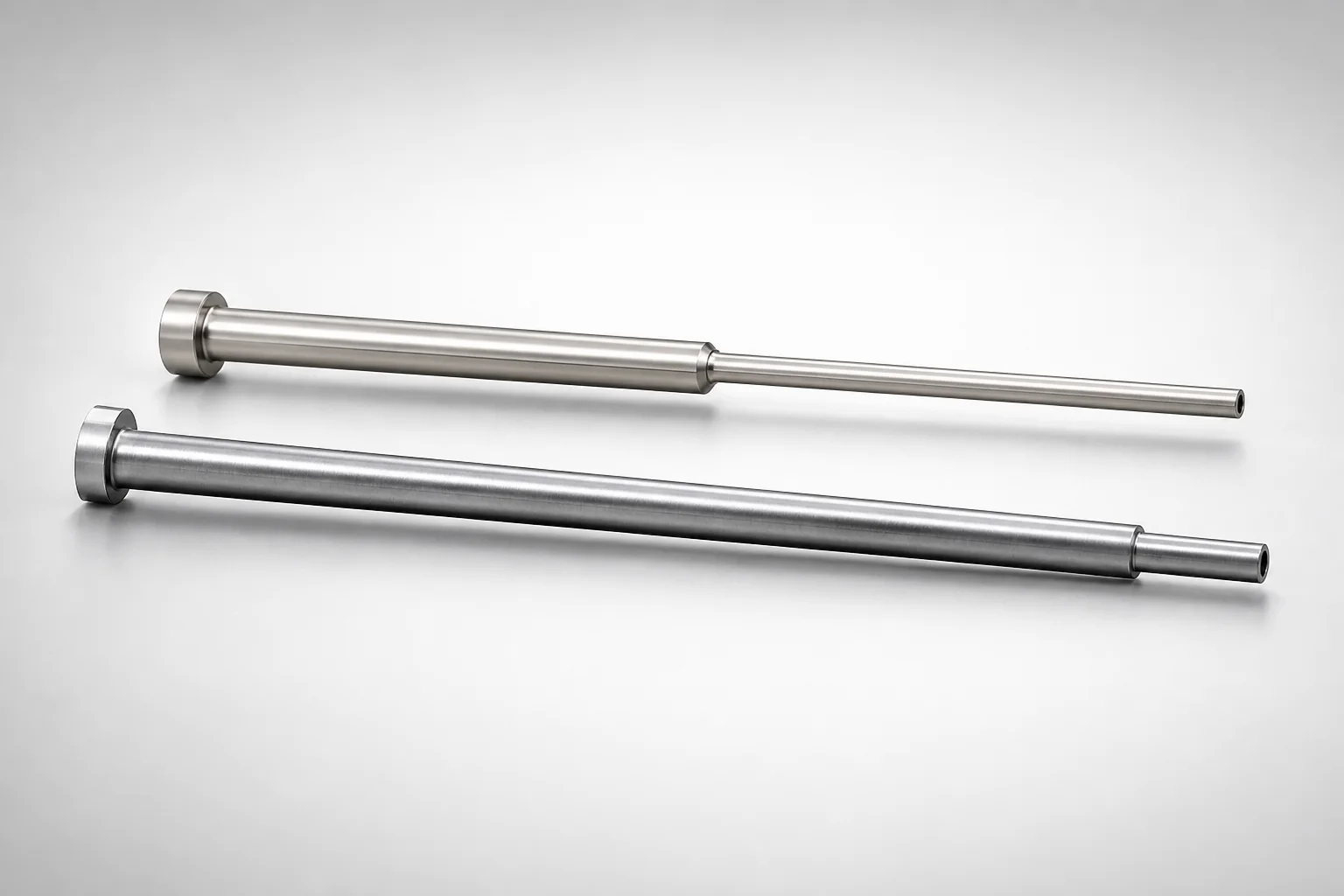
JIS Standard SKH51 Steel Precision Stepped Ejector Sleeves (ESVF)
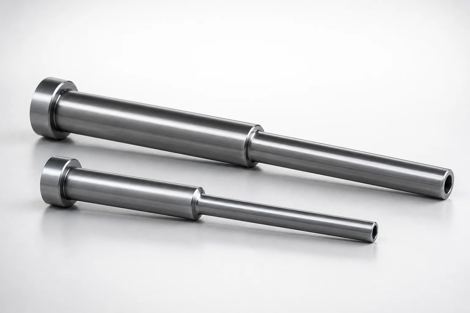
JIS Standard SKD61 Steel Stepped Ejector Sleeves
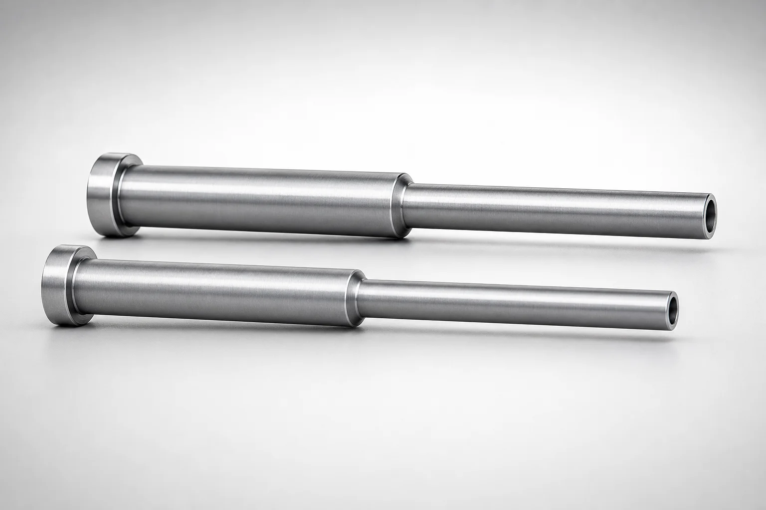
JIS Standard SKD61 Steel Stepped Ejector Sleeves
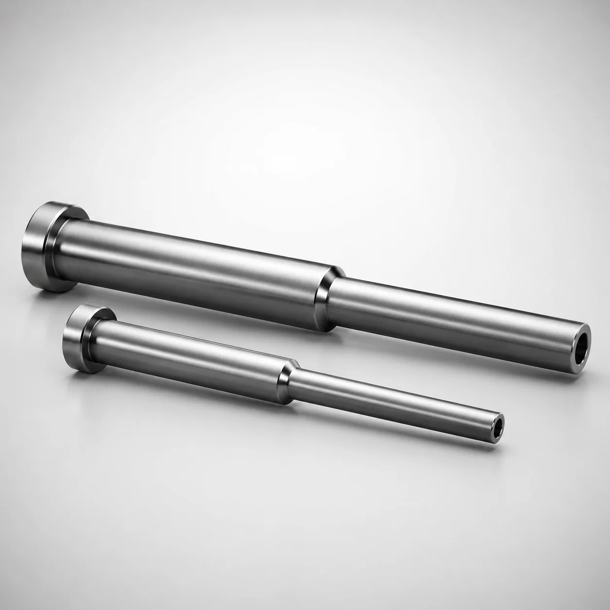
ESNF Type SKD61 Hardened Steel Stepped Ejector Sleeves
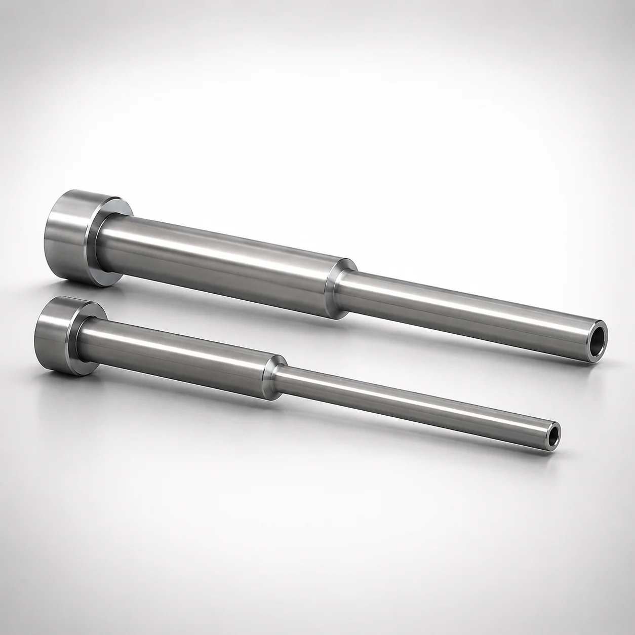
JIS Standard SKD61 Steel Stepped Ejector Sleeves
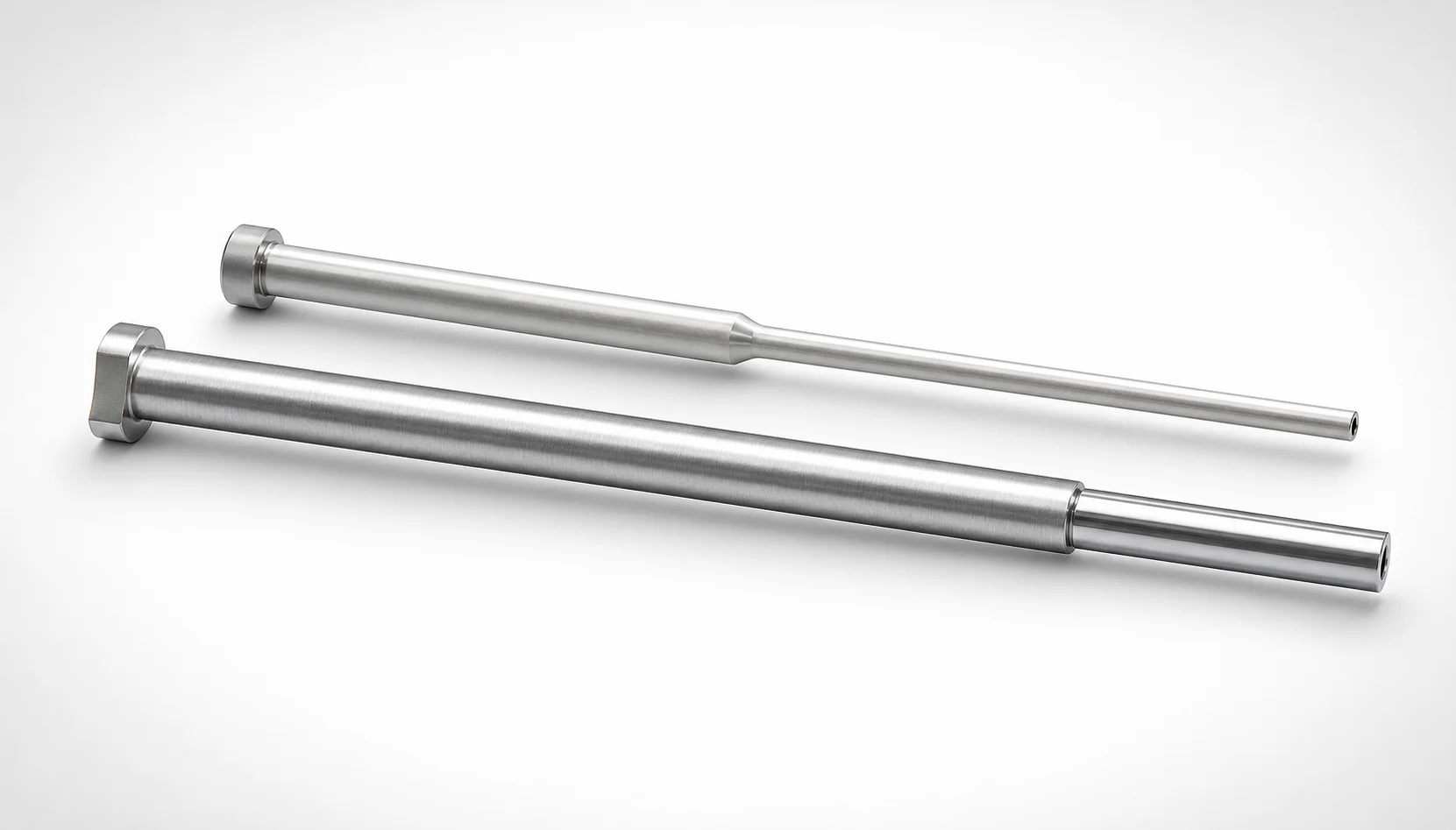
JIS Standard SKH51 Steel Precision Stepped Ejector Sleeves
Need Custom Specifications?
Our engineering team can help with custom configurations, material selection, and volume pricing.