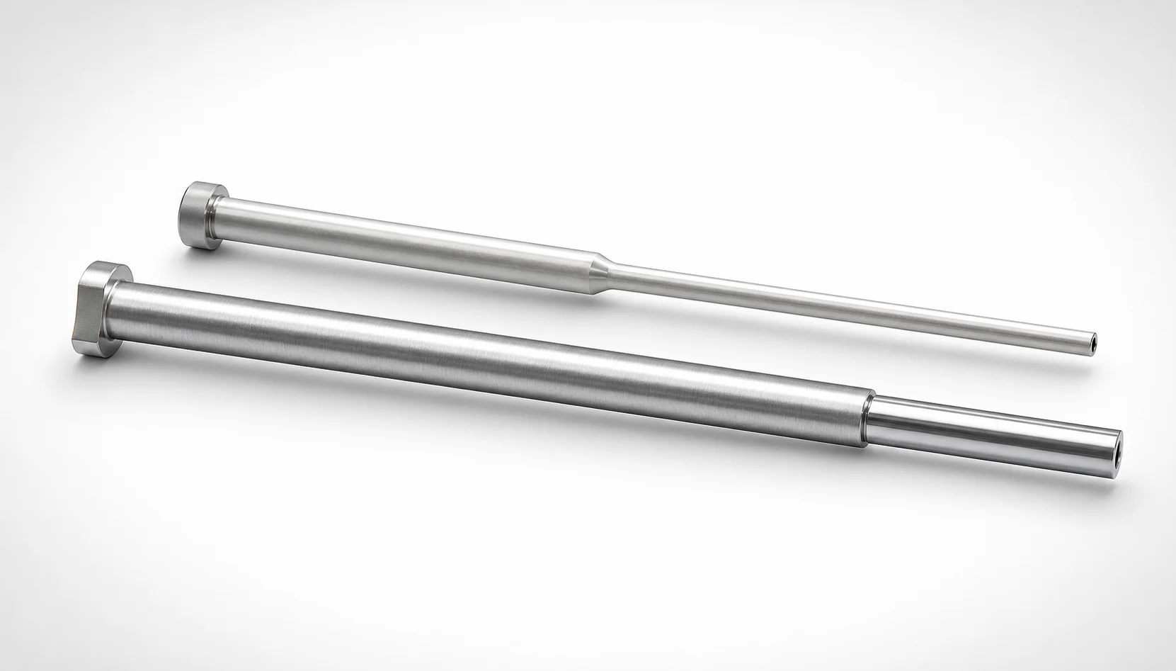
JIS Standard SKH51 Steel Precision Stepped Ejector Sleeves
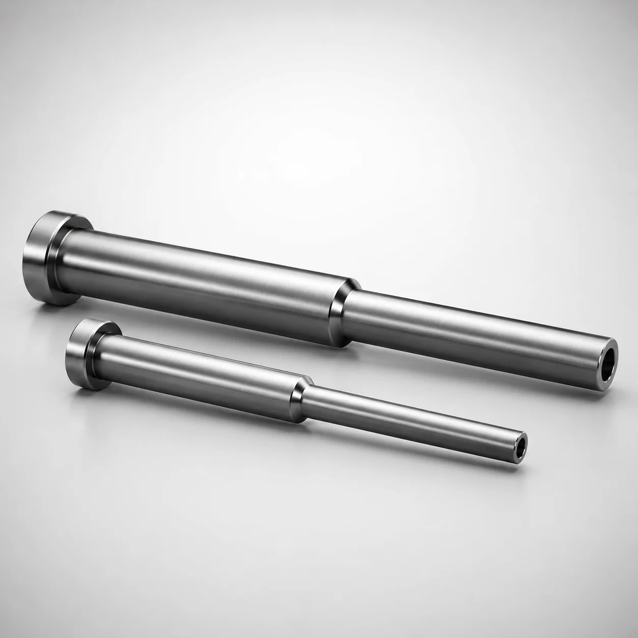
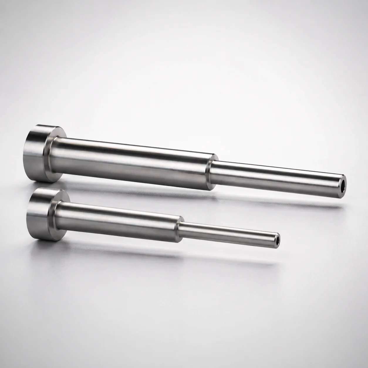
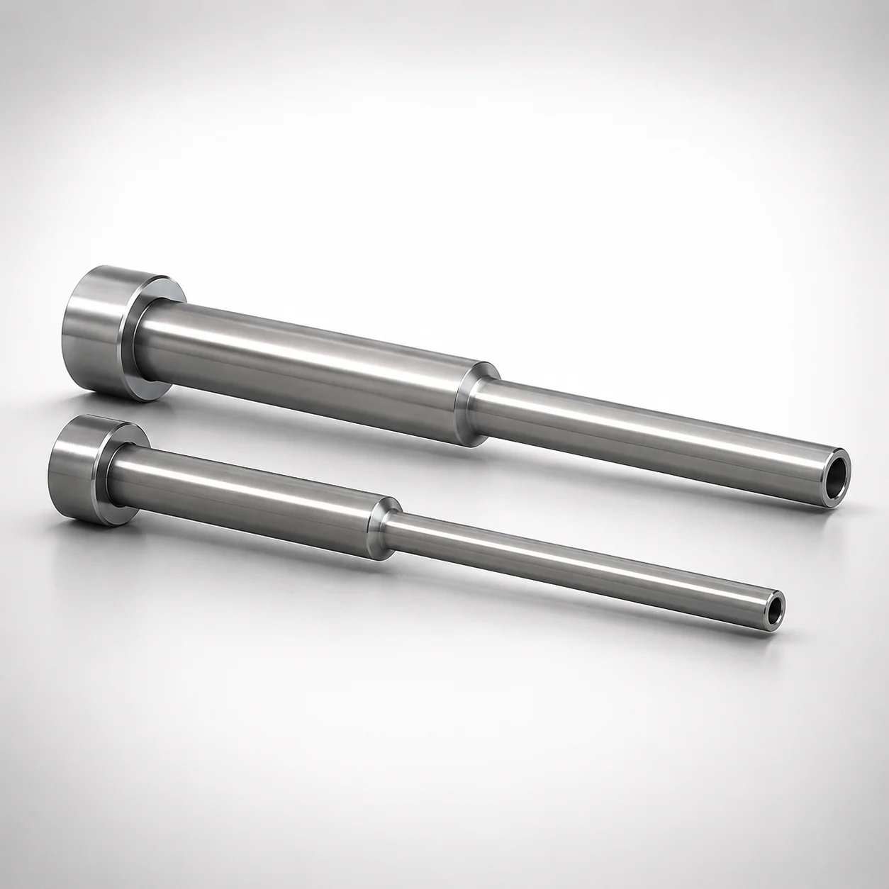
Precision stepped ejector sleeves (SKH51 steel) deliver stable part ejection in injection molding where small diameters and thin walls are required, supported by a long bearing design for consistent removal performance.
- Stepped ejector sleeve geometry improves controlled ejection of small, sensitive components
- SKH51 steel construction with quenched hardening steel provides wear-resistant sleeve performance
- Precision fit supports repeatable alignment and consistent ejection cycle behavior in production
- Designed for standard mold interfaces with ESVKF-H type configuration for reliable operation
Specifications
9 configurations available
| D (Shaft Diameter) (mm) | P (Tip Diameter) (mm) | V (Hole Diameter) (mm) | L (L dimension) (mm) | Dimension N (mm) | S (V hole diameter length) (mm) | type |
|---|---|---|---|---|---|---|
| 3 | 1.8 ~ 2.95 | 0.8 ~ 2.1 | 40 ~ 125 | 20 ~ 115 | 1 ~ 21 | - |
| 3.5 | 1.8 ~ 3.45 | 0.8 ~ 2.6 | 40 ~ 125 | 20 ~ 115 | 1 ~ 26 | - |
| 4 | 1.9 ~ 3.95 | 0.8 ~ 3.1 | 40 ~ 125 | 20 ~ 115 | 1 ~ 30 | - |
| 4.5 | 2.65 ~ 4.45 | 1.1 ~ 3.6 | 40 ~ 125 | 20 ~ 115 | 1 ~ 30 | - |
| 5 | 2.65 ~ 4.95 | 1.2 ~ 4.1 | 40 ~ 125 | 20 ~ 115 | 1 ~ 30 | - |
| 5.5 | 2.65 ~ 5.45 | 1.2 ~ 4.6 | 40 ~ 125 | 20 ~ 115 | 1 ~ 30 | - |
| 6 | 2.9 ~ 5.95 | 1.6 ~ 5.1 | 40 ~ 150 | 20 ~ 140 | 1 ~ 30 | - |
| 2.6 ~ 6 | - | 0.8 ~ 5.1 | 40 ~ 150 | 20 ~ 140 | 1 ~ 30 | - |
| 2.6 ~ 6 | 1.8 ~ 5.9 | 0.8 ~ 5.1 | 40 ~ 150 | 20 ~ 140 | 1 ~ 30 | - |
Product Guide
Application Scenarios+
This precision stepped ejector sleeve is used inside injection mold tool sets to drive and stabilize ejection forces on small, thin-walled components. Its stepped geometry supports controlled contact and reduces the risk of uneven pushing, which is especially valuable for automotive connector molds and other housings that require consistent terminal or insert clearing.
In electronics enclosure and sensor cover molds, the sleeve’s small tip diameter (P: 1.8–2.9 mm) and compact hole size enable reliable bearing removal performance without excessive disturbance to surrounding features. The SKH51 variant is suited for this task because it provides good wear resistance under repeated ejection cycles.
- Use when long, stable bearing removal is needed over the working length (L: 40–125 mm or 40–150 mm).
- Match to the specified mold interface configuration (E-SVKF-H type) to maintain alignment and cycle repeatability.
Material & Process Details+
SKH51 steel is a high-performance Japanese tool steel commonly used for precision wear parts, offering a strong balance of abrasion resistance and service toughness for ejector components. In this sleeving application, the material is intended to resist polishing and edge wear caused by repeated sliding during ejection.
- Heat treatment state: quenched hardening steel (as supplied/treated for wear-resistant sleeve performance).
- Hardness: typically specified for hardened tool steel sleeves; exact HRC depends on the supplier’s final condition and is controlled to maintain dimensional stability.
Trade-offs: higher hardness improves wear resistance for thin-wall and small-diameter bearings, but may reduce toughness if over-heat treated. Compared with lower-alloy steels, SKH51 generally provides better wear resistance for long ejection running, while demanding consistent heat treatment control to avoid dimensional drift.
Sizing & Selection Guide+
Select the stepped ejector sleeve dimensions by matching the ejection interface to your mold’s core/cavity layout and guidance requirements. Start with the shaft diameter (D: 2.6–6 mm) to fit the mating bore or guide feature, then verify the tip diameter (P: 1.8–2.9 mm) for the contact region that clears the molded part.
- Confirm the hole diameter (V: 0.8–1.6 mm) and V-hole diameter length (S: 1–21 / 1–26 / 1–30 mm) so the sleeve geometry aligns with the ejector pin or retaining feature path.
- Choose the correct L (40–125 mm or 40–150 mm) to cover the full working stroke and to maintain stable bearing removal across the expected ejection travel.
- Use N (20–115 mm or 20–140 mm) as the stepped reference length to ensure the transition and shoulder locate correctly within the mold stack.
Where close fit is required, rely on the sleeve’s precision fit to maintain alignment; always validate clearance with your mold assembly drawings to account for thermal expansion and manufacturing tolerances.
Frequently Asked Questions
Which diameter should I prioritize when designing for stable guidance: D (shaft) or P (tip)?+
Prioritize D (2.6–6 mm) to ensure the sleeve aligns properly with the mating guide bore and maintains straight travel. Then verify P (1.8–2.9 mm) because it defines the effective contact/tip region for controlled ejection of small parts. For long bearing removal, confirm the chosen L (40–125 mm or 40–150 mm) matches your required working length.
How do I select the correct V-hole parameters (V and S) for compatibility with the ejector pin arrangement?+
Use V (0.8–1.6 mm) to match the expected hole diameter in your interface design. Then select S (1–21 / 1–26 / 1–30 mm) to ensure the V-hole diameter length covers the required engagement zone. Confirm both values against your stack-up so the pin path and bearing area align during ejection cycles.
When should I choose L = 40–125 mm versus L = 40–150 mm?+
Choose L = 40–125 mm when your working stroke and mold stack require a shorter sleeve length. Choose L = 40–150 mm when deeper guidance or longer bearing removal stability is needed. Always check that the sleeve shoulder reference lengths (N: 20–115 or 20–140 mm) locate correctly to avoid misalignment.
What does the SKH51 steel condition imply for wear life under repeated ejection?+
This sleeve uses SKH51 steel in a quenched hardening state to improve wear-resistant performance under repeated sliding contact. Higher hardness generally enhances resistance to polishing and edge wear, which is critical for thin-wall and small-diameter parts. To balance wear and toughness, follow the supplier’s final heat-treatment condition rather than estimating performance from material alone.
Is this sleeve compatible with the E-SVKF-H mold interface configuration?+
The product is designed for standard mold interfaces using the ESVKF-H type configuration. When integrating into your tool, confirm the mating dimensions (especially D, and the stepped reference N) and verify the assembly’s alignment. This helps ensure repeatable ejection cycle behavior and stable bearing removal performance.
Related Products
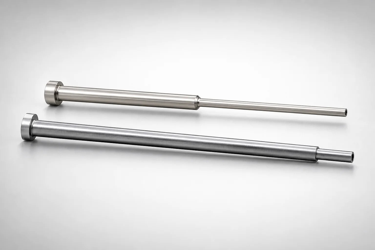
JIS Standard SKH51 Steel Precision Stepped Ejector Sleeves (ESVF)
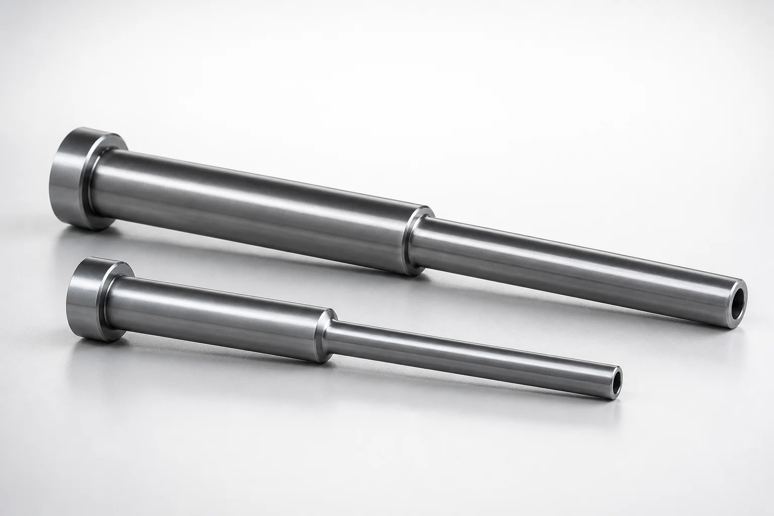
JIS Standard SKD61 Steel Stepped Ejector Sleeves
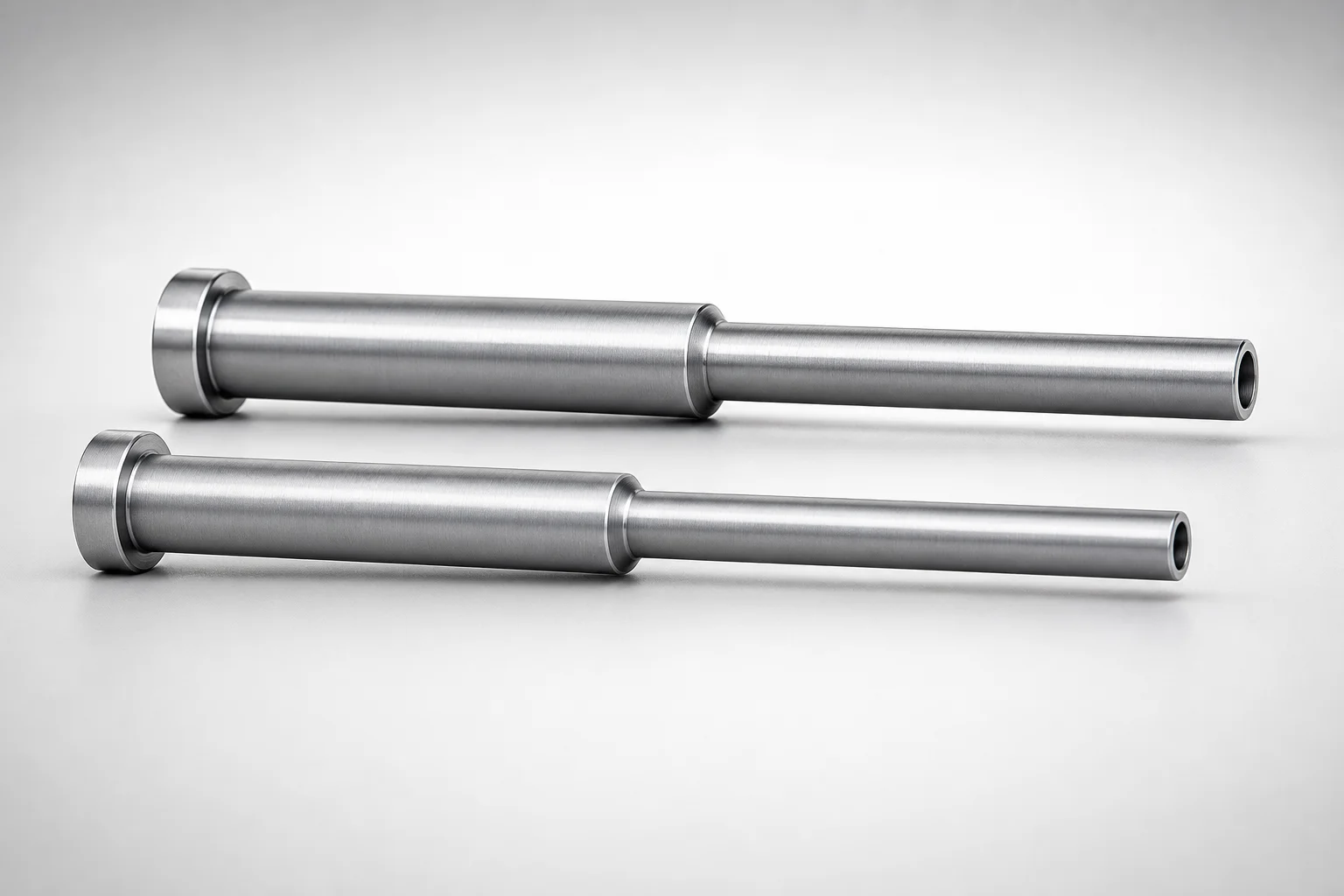
JIS Standard SKD61 Steel Stepped Ejector Sleeves
ESNF Type SKD61 Hardened Steel Stepped Ejector Sleeves
Japanese Standard SKD61 Steel Stepped Ejector Sleeves
JIS Standard SKD61 Steel Stepped Ejector Sleeves
Need Custom Specifications?
Our engineering team can help with custom configurations, material selection, and volume pricing.