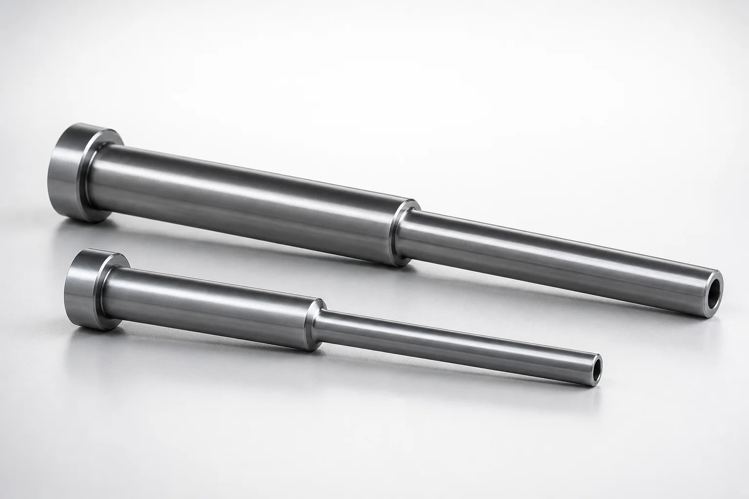
JIS Standard SKD61 Steel Stepped Ejector Sleeves
Stepped ejector sleeves (SKD61 steel) with a nitrided surface treatment provide stable sleeve guidance and improved wear resistance for repeatable ejection performance. Designed for stepped bore seating in precision molds.
- Stepped sleeve design supports accurate alignment and smooth ejector movement
- SKD61 steel construction with nitrided surface enhances abrasion resistance
- Controlled H7 inner-diameter tolerance and matched shaft tolerance improve fit stability
- Built to JIS standard for consistent compatibility in mold assemblies
Specifications
44 configurations available
| Head Thickness | D (Shaft Diameter) (mm) | P (Tip Diameter) (mm) | V (Hole Diameter) (mm) | C (Recess diameter) (mm) | L (L dimension) (mm) | Dimension N (mm) | S (V hole diameter length) (mm) | type |
|---|---|---|---|---|---|---|---|---|
| 6mm(JIS) | 5 | 3.5 ~ 4.95 | 2 ~ 3 | 2.5 ~ 3.5 | 50 ~ 300 | - | 20 ~ 50 | - |
| 6mm(JIS) | 5 | 3.5 ~ 4.95 | 2 ~ 3 | 2.5 ~ 3.5 | 50 ~ 300 | 17 ~ 300 | 20 ~ 50 | - |
| 6mm(JIS) | 5.5 | 3.5 ~ 5.45 | 2 ~ 3.5 | 2.5 ~ 4 | 50 ~ 300 | - | 20 ~ 50 | - |
| 6mm(JIS) | 5.5 | 3.5 ~ 5.45 | 2 ~ 3.5 | 2.5 ~ 4 | 50 ~ 300 | 17 ~ 300 | 20 ~ 50 | - |
| 6mm(JIS) | 6 | 4 ~ 5.95 | 2 ~ 4 | 2.5 ~ 4.5 | 50 ~ 300 | - | 20 ~ 50 | - |
| 6mm(JIS) | 6 | 4 ~ 5.95 | 2 ~ 4 | 2.5 ~ 4.5 | 50 ~ 300 | 17 ~ 500 | 20 ~ 50 | - |
| 6mm(JIS) | 6 | 4 ~ 5.95 | 2 ~ 4 | 2.5 ~ 4.5 | 50 ~ 300 | - | 20 ~ 50 | - |
| 6mm(JIS) | 6 | 4 ~ 5.95 | 2 ~ 4 | 2.5 ~ 4.5 | 50 ~ 300 | 17 ~ 500 | 20 ~ 50 | - |
| 6mm(JIS) | 6.5 | 4 ~ 6.45 | 2 ~ 4.5 | 2.5 ~ 5 | 50 ~ 300 | - | 20 ~ 50 | - |
| 6mm(JIS) | 6.5 | 4 ~ 6.45 | 2 ~ 4.5 | 2.5 ~ 5 | 50 ~ 300 | 17 ~ 500 | 20 ~ 50 | - |
| 6mm(JIS) | 6.5 | 4 ~ 6.45 | 2 ~ 4.5 | 2.5 ~ 5 | 50 ~ 300 | - | 20 ~ 50 | - |
| 6mm(JIS) | 6.5 | 4 ~ 6.45 | 2 ~ 4.5 | 2.5 ~ 5 | 50 ~ 300 | 17 ~ 500 | 20 ~ 50 | - |
| 6mm(JIS) | 7 | 4 ~ 6.95 | 2 ~ 4.5 | 2.5 ~ 5 | 50 ~ 300 | - | 20 ~ 50 | - |
| 6mm(JIS) | 7 | 4 ~ 6.95 | 2 ~ 4.5 | 2.5 ~ 5 | 50 ~ 300 | 17 ~ 500 | 20 ~ 50 | - |
| 6mm(JIS) | 7 | 4 ~ 6.95 | 2 ~ 4.5 | 2.5 ~ 5 | 50 ~ 300 | - | 20 ~ 50 | - |
| 6mm(JIS) | 7 | 4 ~ 6.95 | 2 ~ 4.5 | 2.5 ~ 5 | 50 ~ 300 | 17 ~ 500 | 20 ~ 50 | - |
| 6mm(JIS) | 7.5 | 4 ~ 7.45 | 2 ~ 5 | 2.5 ~ 5.5 | 50 ~ 300 | - | 20 ~ 50 | - |
| 6mm(JIS) | 7.5 | 4 ~ 7.45 | 2 ~ 5 | 2.5 ~ 5.5 | 50 ~ 300 | 17 ~ 500 | 20 ~ 50 | - |
| 6mm(JIS) | 7.5 | 4 ~ 7.45 | 2 ~ 5 | 2.5 ~ 5.5 | 50 ~ 300 | - | 20 ~ 50 | - |
| 6mm(JIS) | 7.5 | 4 ~ 7.45 | 2 ~ 5 | 2.5 ~ 5.5 | 50 ~ 300 | 17 ~ 500 | 20 ~ 50 | - |
| 8mm(JIS) | 8 | 5 ~ 7.95 | 2.5 ~ 5.5 | 3 ~ 6 | 70 ~ 300 | 24 ~ 500 | 20 ~ 50 | - |
| 8mm(JIS) | 8 | 5 ~ 7.95 | 2.5 ~ 5.5 | 3 ~ 6 | 70 ~ 300 | 24 ~ 500 | 20 ~ 50 | - |
| 8mm(JIS) | 9 | 6 ~ 8.95 | 3 ~ 6.5 | 3.5 ~ 7 | 70 ~ 300 | 24 ~ 490 | 20 ~ 50 | - |
| 8mm(JIS) | 9 | 6 ~ 8.95 | 3 ~ 6.5 | 3.5 ~ 7 | 70 ~ 300 | 24 ~ 490 | 20 ~ 50 | - |
| 8mm(JIS) | 10 | 6 ~ 9.95 | 3.5 ~ 7.5 | 4 ~ 8 | 70 ~ 300 | 24 ~ 500 | 20 ~ 50 | - |
| 8mm(JIS) | 10 | 6 ~ 9.95 | 3.5 ~ 7.5 | 4 ~ 8 | 70 ~ 300 | 24 ~ 500 | 20 ~ 50 | - |
| 4mm(T4) | 4 | 3 ~ 3.95 | 1.5 ~ 2 | 2 ~ 2.9 | 50 ~ 200 | - | 20 ~ 100 | - |
| 4mm(T4) | 4 | 3 ~ 3.95 | 1.5 ~ 2 | 2 ~ 2.9 | 50 ~ 200 | 17 ~ 220 | 20 ~ 100 | - |
| 4mm(T4) | 4.5 | 3 ~ 4.45 | 1.5 ~ 2.5 | 2 ~ 2.9 | 50 ~ 200 | - | 20 ~ 100 | - |
| 4mm(T4) | 4.5 | 3 ~ 4.45 | 1.5 ~ 2.5 | 2 ~ 2.9 | 50 ~ 200 | 17 ~ 220 | 20 ~ 100 | - |
| 4mm(T4) | 4.5 | 3 ~ 4.45 | 1.5 ~ 2.5 | 3.05 ~ 3.45 | 50 ~ 200 | - | 20 ~ 100 | - |
| 4mm(T4) | 4.5 | 3 ~ 4.45 | 1.5 ~ 2.5 | 3.05 ~ 3.45 | 50 ~ 200 | 17 ~ 220 | 20 ~ 100 | - |
| 4mm(T4) | 5 | 3.5 ~ 4.95 | 2 ~ 3 | 2.5 ~ 3.5 | 50 ~ 250 | - | 20 ~ 50 | - |
| 4mm(T4) | 5 | 3.5 ~ 4.95 | 2 ~ 3 | 2.5 ~ 3.5 | 50 ~ 250 | 17 ~ 240 | 20 ~ 50 | - |
| 4mm(T4) | 5.5 | 3.5 ~ 5.45 | 2 ~ 3.5 | 2.5 ~ 4 | 50 ~ 250 | 17 ~ 240 | 20 ~ 50 | - |
| 4mm(T4) | 6 | 4 ~ 5.95 | 2 ~ 4 | 2.5 ~ 4.5 | 50 ~ 300 | - | 20 ~ 50 | - |
| 4mm(T4) | 6 | 4 ~ 5.95 | 2 ~ 4 | 2.5 ~ 4.5 | 50 ~ 300 | 17 ~ 290 | 20 ~ 50 | - |
| 4mm(T4) | 6.5 | 4 ~ 6.45 | 2 ~ 4.5 | 2.5 ~ 5 | 50 ~ 300 | 17 ~ 290 | 20 ~ 50 | - |
| 4mm(T4) | 7 | 4 ~ 6.95 | 2 ~ 5 | 2.5 ~ 5.5 | 50 ~ 300 | 17 ~ 290 | 20 ~ 50 | - |
| 4mm(T4) | 7.5 | 4 ~ 7.45 | 2 ~ 5.5 | 2.5 ~ 6 | 50 ~ 300 | 17 ~ 290 | 20 ~ 50 | - |
| 4mm(T4) | 8 | 4 ~ 7.95 | 2.5 ~ 6 | 3 ~ 6.5 | 50 ~ 300 | - | 20 ~ 50 | - |
| 4mm(T4) | 8 | 4 ~ 7.95 | 2.5 ~ 6 | 3 ~ 6.5 | 50 ~ 300 | 17 ~ 290 | 20 ~ 50 | - |
| 4mm(T4) | 9 | 4.5 ~ 8.95 | 2.5 ~ 6.9 | 3 ~ 7.5 | 50 ~ 300 | 17 ~ 290 | 20 ~ 50 | - |
| 4mm(T4) | 10 | 4.5 ~ 9.95 | 2.5 ~ 7.9 | 3 ~ 8.5 | 50 ~ 300 | 17 ~ 290 | 20 ~ 50 | - |
Product Guide
Application Scenarios+
Stepped ejector sleeves in SKD61 with a nitrided surface are commonly used in injection mold toolsets where long-term guidance and consistent ejection force transfer are critical. The stepped geometry seats into a matching stepped bore, helping maintain alignment during cycling.
- Automotive connector and housing molds: Use these sleeves on ejector systems that experience high repetition and abrasive contamination. The nitrided surface supports stable sliding and improved wear resistance, helping reduce variation in ejection stroke.
- Appliance and consumer electronics enclosure molds: Stepped sleeves are suited for precision ejection where smooth movement prevents scuffing and misalignment. The controlled H7 inner-diameter tolerance supports reliable fit with the mating ejector elements.
- Industrial housings requiring repeatable ejection: For toolsets that must hold geometry over many production cycles, SKD61 steel plus surface nitriding improves abrasion resistance while retaining toughness for reliable ejector operation.
Material & Process Details+
This component is made from JIS SKD61 steel (H13-equivalent class tool steel), selected for its balance of hardness, toughness, and hot-working performance in mold bases and ejector parts. After machining, it is typically supplied in a heat-treated condition appropriate for ejector guidance; the defining wear-improvement feature here is the nitrided surface treatment.
- Nitriding: Produces a hard, wear-resistant surface layer that resists abrasion from ejector sliding and particulate contamination.
- Hardness / trade-offs: Nitrided surfaces improve wear resistance, while the core remains tougher for shock resistance during ejection events.
- Wear vs. toughness: Compared with through-hardened approaches, nitriding targets surface durability while preserving the SKD61 core’s toughness for stable operation under cyclic loading.
Sizing & Selection Guide+
Select the stepped ejector sleeve dimensions by matching the cavity/core interface and the mating ejector shaft requirements. Use D (shaft diameter) = 4–10 mm to fit the ejector shaft you intend to guide, and choose P (tip diameter) = 3–6 mm and V (hole diameter) = 1.5–3.5 mm to reflect the stepped features in your mold assembly.
- Recess and locating features: Match C (recess diameter) = 2–4 mm and Dimension N = 17–24 mm to the stepped bore seating geometry.
- Length control: Confirm L (L dimension) options: 50–300, 70–300, 50–200, or 50–250 mm based on your required ejection travel and tool stack-up; verify S (V hole length) = 20–50 or 20–100 mm.
- Tolerance and fit: The sleeve includes a controlled H7 inner-diameter tolerance; ensure the mating shaft tolerance is compatible to achieve stable guidance with minimal play.
Frequently Asked Questions
How does the H7 inner-diameter tolerance affect fit with the ejector shaft for these stepped sleeves?+
The sleeve is specified with a controlled H7 inner-diameter tolerance. This tolerance level is intended to provide stable guidance when paired with a properly matched shaft diameter in the D = 4–10 mm range. For best movement repeatability, align mating shaft tolerance to prevent excessive clearance (wobble) or interference (binding).
Which dimension(s) must match the stepped bore geometry in the mold core or cavity?+
The sleeve is designed for stepped bore seating, so geometry around the recess and overall stepped interface must be matched. Focus on C (recess diameter) = 2–4 mm and Dimension N = 17–24 mm, along with the selected Head Thickness options (6 mm (JIS), 8 mm (JIS), or 4 mm (T4)).
What are the key diameter ranges for designing the shaft and tip features?+
For shaft guidance, use D (shaft diameter) = 4–10 mm. For the stepped tip feature, select P (tip diameter) = 3–6 mm. If your tool design includes a through or pocket feature, also confirm V (hole diameter) = 1.5–3.5 mm and S (V hole diameter length) = 20–50 or 20–100 mm.
Why choose SKD61 with nitriding for ejector sleeve wear resistance rather than relying only on steel hardness?+
The variant is described as SKD61 steel with a nitrided surface, which is intended to improve abrasion resistance at the sliding interface. This approach emphasizes surface wear resistance while maintaining a tougher core for cyclic ejector operation. In practical toolsets, that reduces wear-related changes to guidance and supports repeatable ejection performance.
How do I select the correct head thickness for compatibility in the tool stack-up?+
Choose the Head Thickness according to your mold stack-up and the stepped bore depth requirement: 6 mm (JIS), 8 mm (JIS), or 4 mm (T4). After selecting head thickness, verify the overall L length option that best fits your required ejection travel (e.g., 50–300 or 70–300 mm ranges).
Related Products
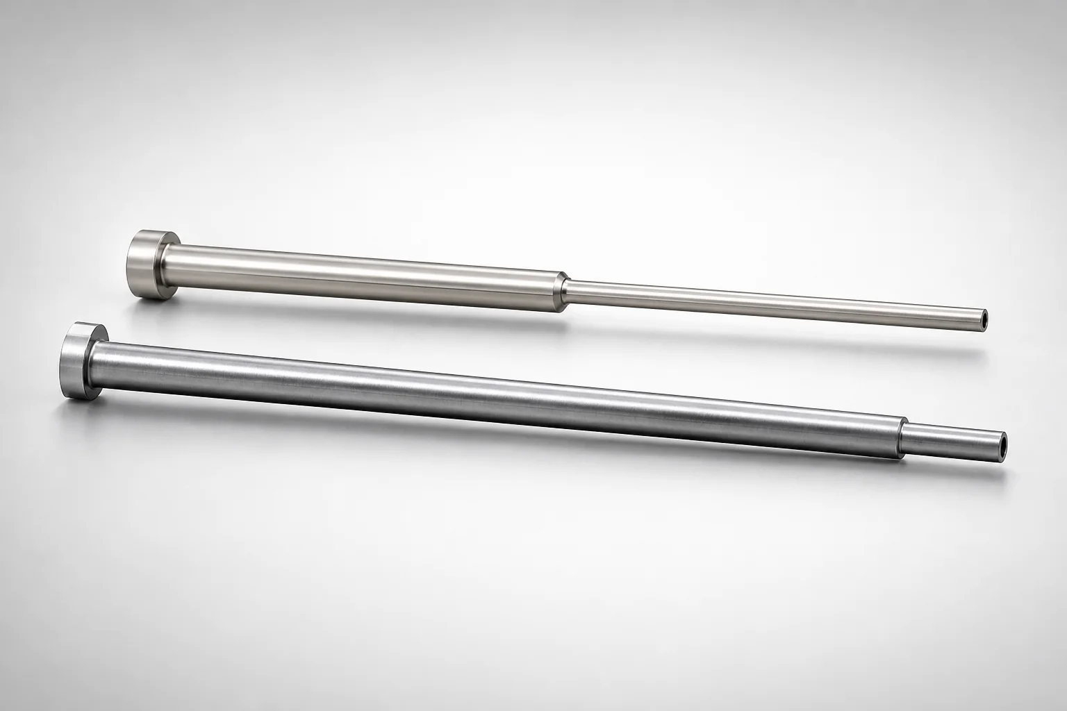
JIS Standard SKH51 Steel Precision Stepped Ejector Sleeves (ESVF)
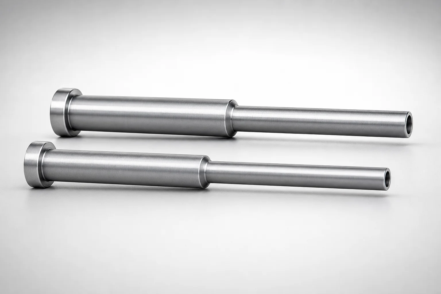
JIS Standard SKD61 Steel Stepped Ejector Sleeves
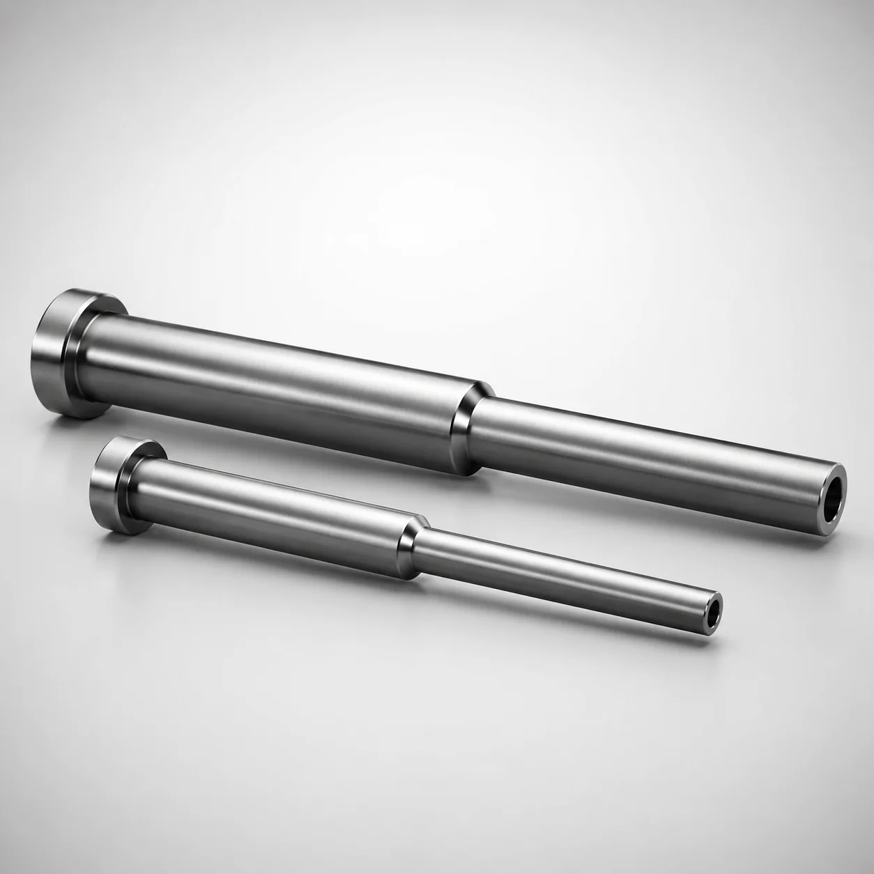
ESNF Type SKD61 Hardened Steel Stepped Ejector Sleeves
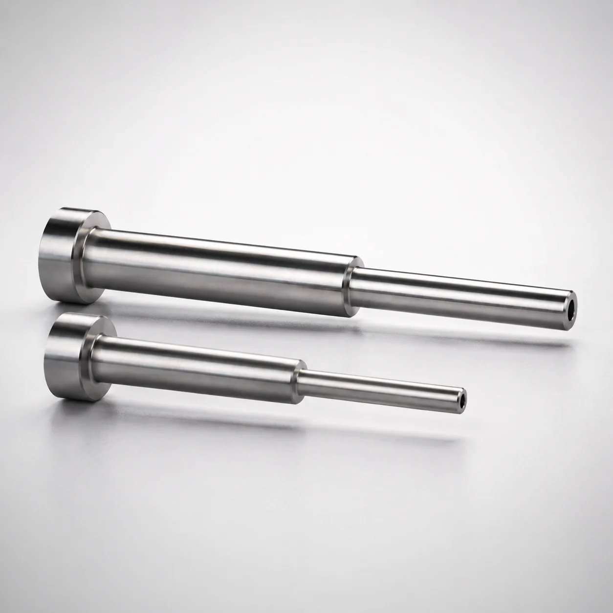
Japanese Standard SKD61 Steel Stepped Ejector Sleeves
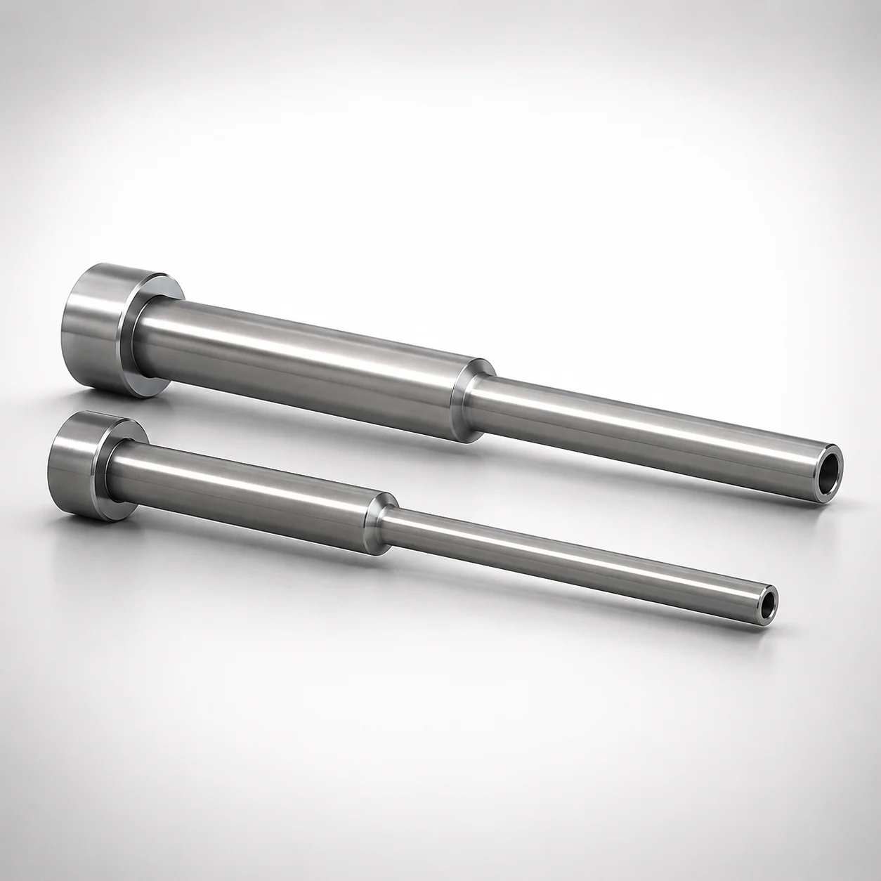
JIS Standard SKD61 Steel Stepped Ejector Sleeves
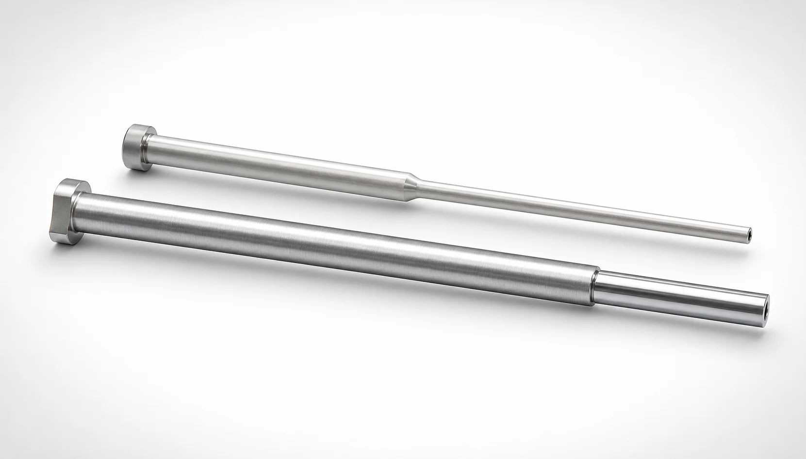
JIS Standard SKH51 Steel Precision Stepped Ejector Sleeves
Need Custom Specifications?
Our engineering team can help with custom configurations, material selection, and volume pricing.