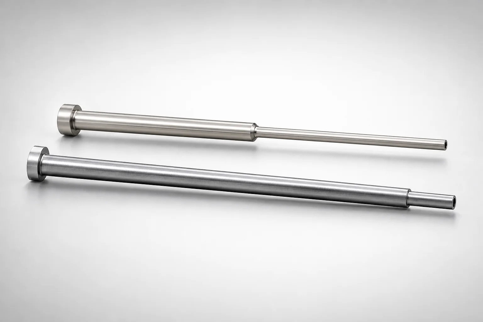
JIS Standard SKH51 Steel Precision Stepped Ejector Sleeves (ESVF)
Precision stepped ejector sleeves (ESVF) (SKH51 steel) are engineered for accurate, low-deflection guidance in mold ejector systems, delivering stable stepped support for repeatable alignment.
- Thin-wall stepped sleeve design supports precise positioning with a single-sleeve structure
- SKH51 steel construction with quenched and hardened performance for wear resistance
- Controlled inner diameter tolerance +0.005/0 and shaft tolerance 0/-0.005 for consistent fit
- Built for stepped ejector applications using the ESVF type configuration
Specifications
8 configurations available
| D (Shaft Diameter) (mm) | P (Tip Diameter) (mm) | V (Hole Diameter) (mm) | L (L dimension) (mm) | Dimension N (mm) | S (V hole diameter length) (mm) | type |
|---|---|---|---|---|---|---|
| 2.5 | 1.8 ~ 2.5 | 0.8 ~ 1.6 | 40 ~ 70 | 20 ~ 60 | 1 ~ 4.5 | - |
| 3 | 1.8 ~ 2.95 | 0.8 ~ 2.1 | 40 ~ 125 | 20 ~ 115 | 1 ~ 6 | - |
| 3.5 | 1.8 ~ 3.45 | 0.8 ~ 2.6 | 40 ~ 125 | 20 ~ 115 | 1 ~ 7.5 | - |
| 4 | 1.9 ~ 3.95 | 0.8 ~ 3.1 | 40 ~ 125 | 20 ~ 115 | 1 ~ 9 | - |
| 4.5 | 2.65 ~ 4.45 | 1.1 ~ 3.6 | 40 ~ 125 | 20 ~ 115 | 1 ~ 10.5 | - |
| 5 | 2.65 ~ 4.95 | 1.2 ~ 4.1 | 40 ~ 125 | 20 ~ 115 | 1 ~ 12 | - |
| 5.5 | 2.65 ~ 5.45 | 1.2 ~ 4.6 | 40 ~ 125 | 20 ~ 115 | 1 ~ 13.5 | - |
| 6 | 2.9 ~ 5.95 | 1.6 ~ 5.1 | 40 ~ 150 | 20 ~ 140 | 1 ~ 15 | - |
Product Guide
Application Scenarios+
These precision stepped ejector sleeves are used inside injection mold ejector assemblies where stable, low-deflection guiding is critical. The thin-wall stepped geometry helps maintain alignment as the ejector stroke loads increase, supporting repeatable positioning from shot to shot.
- Automotive connector and housing molds: In molds with closely spaced ejector pins, the stepped guide provides stable support and consistent alignment during ejection, helping reduce side loading on mating components.
- Consumer electronics enclosure molds: For thin-wall parts requiring tight ejector alignment, the controlled inner diameter and shaft interface allow smooth motion and reduce misalignment over long production runs.
- Medical device housings: Where dimensional stability and reliable ejection are required, the ESVF configuration supports accurate guiding in systems that see frequent cycling.
The SKH51 variant is suited for these applications because it is a precision ejector-steel grade designed for wear resistance at the guiding surfaces, while the stated ID/shaft tolerance targets consistent fit.
Material & Process Details+
JIS Standard SKH51 steel is used for precision ejector sleeve components. In tooling terms, SKH51 is commonly selected for high hardness performance and wear resistance, supporting long service life in guided ejection.
- Hardness / wear-toughness balance: The design description specifies quenched and hardened performance for wear resistance. This typically improves surface durability, but requires attention to maintaining adequate toughness to avoid chipping under shock loading.
- Heat treatment state: Quenched and hardened condition is the stated requirement for this product family, targeting stable dimensions in the sliding/guiding region.
- Manufacturing relevance: Achieving the tight inner diameter tolerance (+0.005 / 0) and shaft tolerance (0 / -0.005) typically depends on precision machining plus finishing after heat treatment.
If alternative tool steels are considered, they must similarly support high wear resistance while maintaining sufficient toughness for ejector impact; SKH51 is positioned for that guiding-surface durability requirement.
Sizing & Selection Guide+
Select the sleeve dimensions by matching the ejector assembly geometry to the mating ejector pin/shaft and the guide bore requirement in the mold. The key interfaces are the shaft diameter (D), the sleeve tip diameter (P), and the hole diameter (V).
- Step 1—Match shaft diameter: Choose D = 2.5 ~ 6 mm to correspond to the ejector shaft you will guide.
- Step 2—Match stepped tip and bore features: Select P = 1.8 ~ 2.9 mm and V = 0.8 ~ 1.6 mm to align with the stepped interface and the functional hole geometry.
- Step 3—Match lengths to cavity/core thickness: Pick L = 40~70, 40~125, or 40~150 mm and the corresponding N = 20~60, 20~115, or 20~140 mm so the guided length covers the region where alignment must be maintained.
Fit is governed by the stated tolerance goals: inner diameter +0.005 / 0 and shaft tolerance 0 / -0.005. Ensure the mating shaft lands within the intended tolerance window to achieve consistent clearance and avoid binding.
Frequently Asked Questions
How do I select the correct sleeve size based on shaft diameter (D) and tip diameter (P)?+
Use D (shaft diameter) from the allowed range of 2.5 ~ 6 mm to match the ejector shaft you are guiding. Then select P (tip diameter) within 1.8 ~ 2.9 mm so the stepped tip interfaces correctly with the mating feature in the ejector system.
What tolerances should I account for when designing the fit with the ejector shaft?+
This product family specifies an inner diameter tolerance of +0.005 / 0 and a shaft tolerance of 0 / -0.005. When designing the assembly, keep the mating shaft within the stated tolerance band to maintain the intended clearance and reduce risk of sticking or uneven motion during cycling.
Which length combination (L and N) should be used for my mold thickness and required guiding length?+
Choose L based on the required overall guided engagement: available options are 40~70, 40~125, or 40~150 mm. For each L option, select the corresponding N value from 20~60, 20~115, or 20~140 mm so the functional stepped section is positioned where alignment is most critical.
What does the ESVF configuration imply for stepped ejector sleeve applications?+
The product is designed for stepped ejector systems using the ESVF type configuration. In practice, this means the sleeve’s geometry is intended to provide stable stepped support and alignment for repeatable ejector motion rather than a single straight guiding length.
Why is SKH51 selected for precision ejector sleeve guidance surfaces?+
SKH51 (JIS Standard) is specified for this sleeve, and the description indicates a quenched and hardened condition aimed at wear resistance. This helps protect the guiding surfaces under repeated sliding and impact loads, while the precision tolerance targets support stable, low-deflection guidance.
Related Products
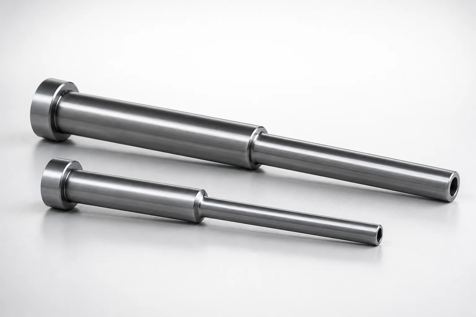
JIS Standard SKD61 Steel Stepped Ejector Sleeves
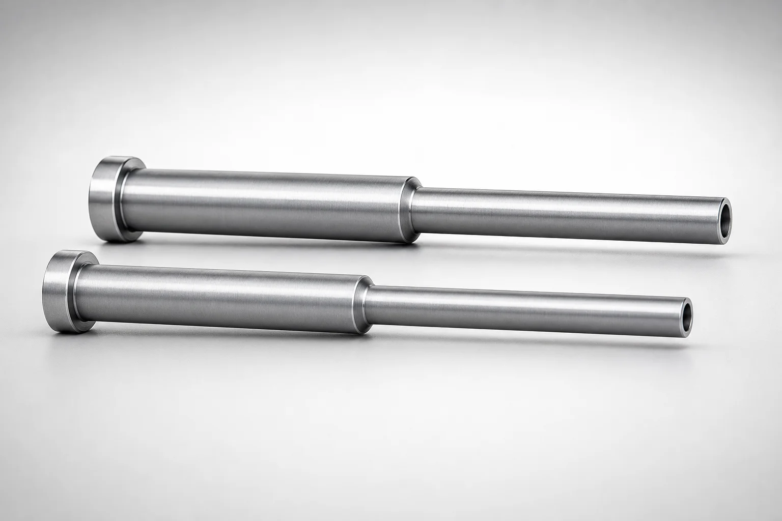
JIS Standard SKD61 Steel Stepped Ejector Sleeves
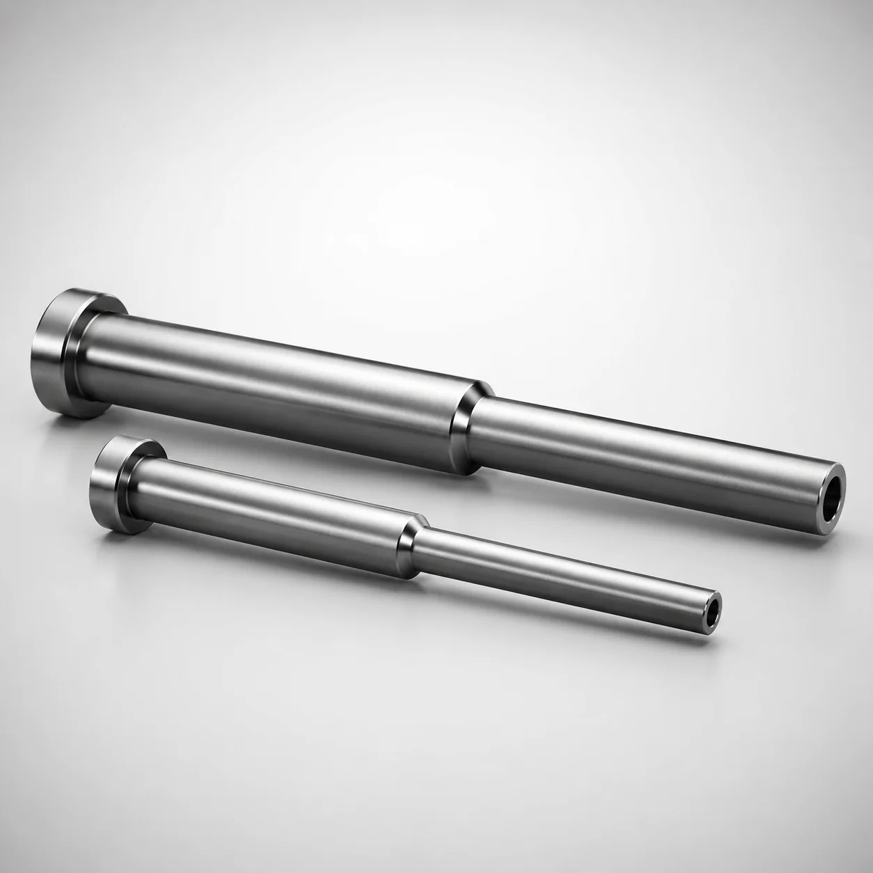
ESNF Type SKD61 Hardened Steel Stepped Ejector Sleeves
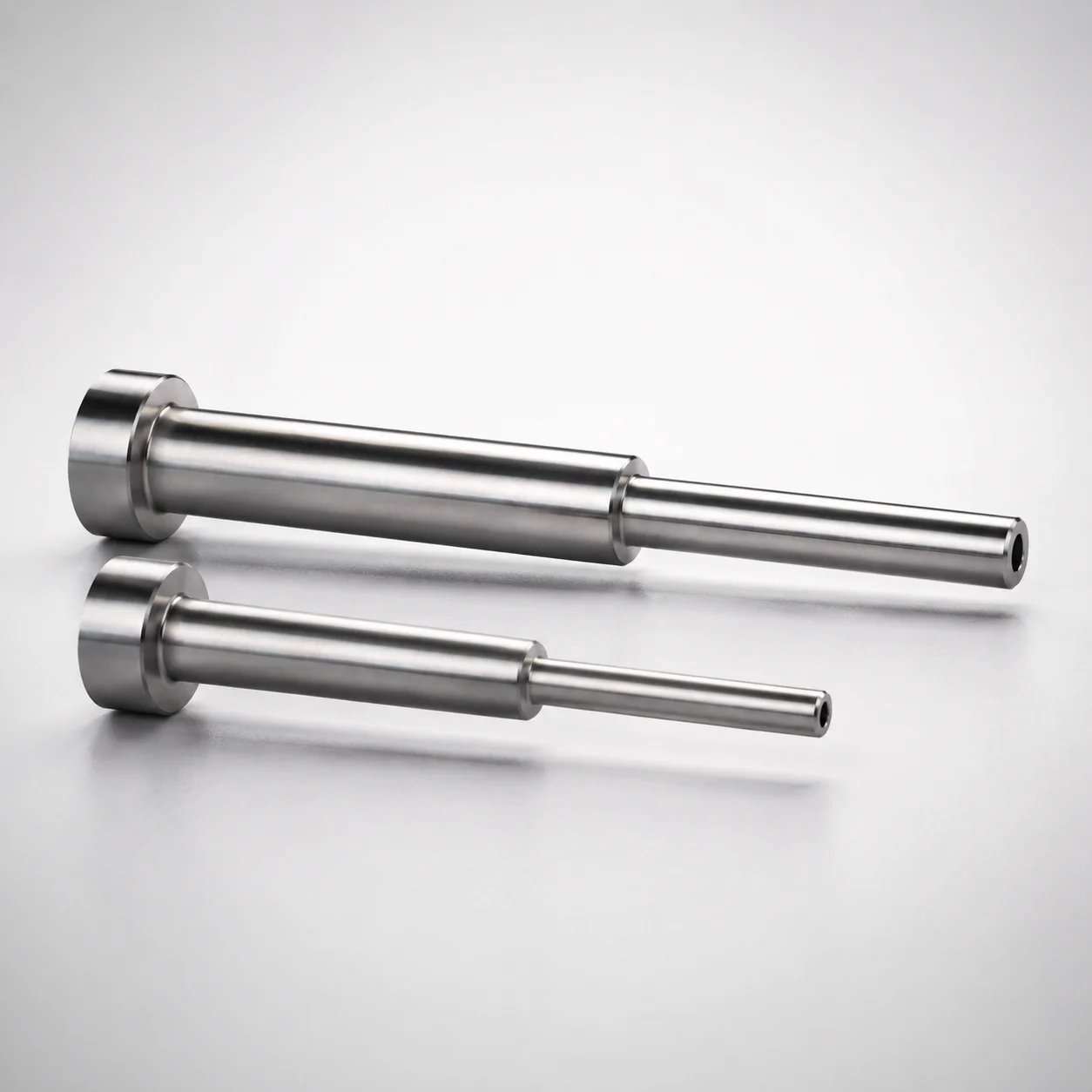
Japanese Standard SKD61 Steel Stepped Ejector Sleeves
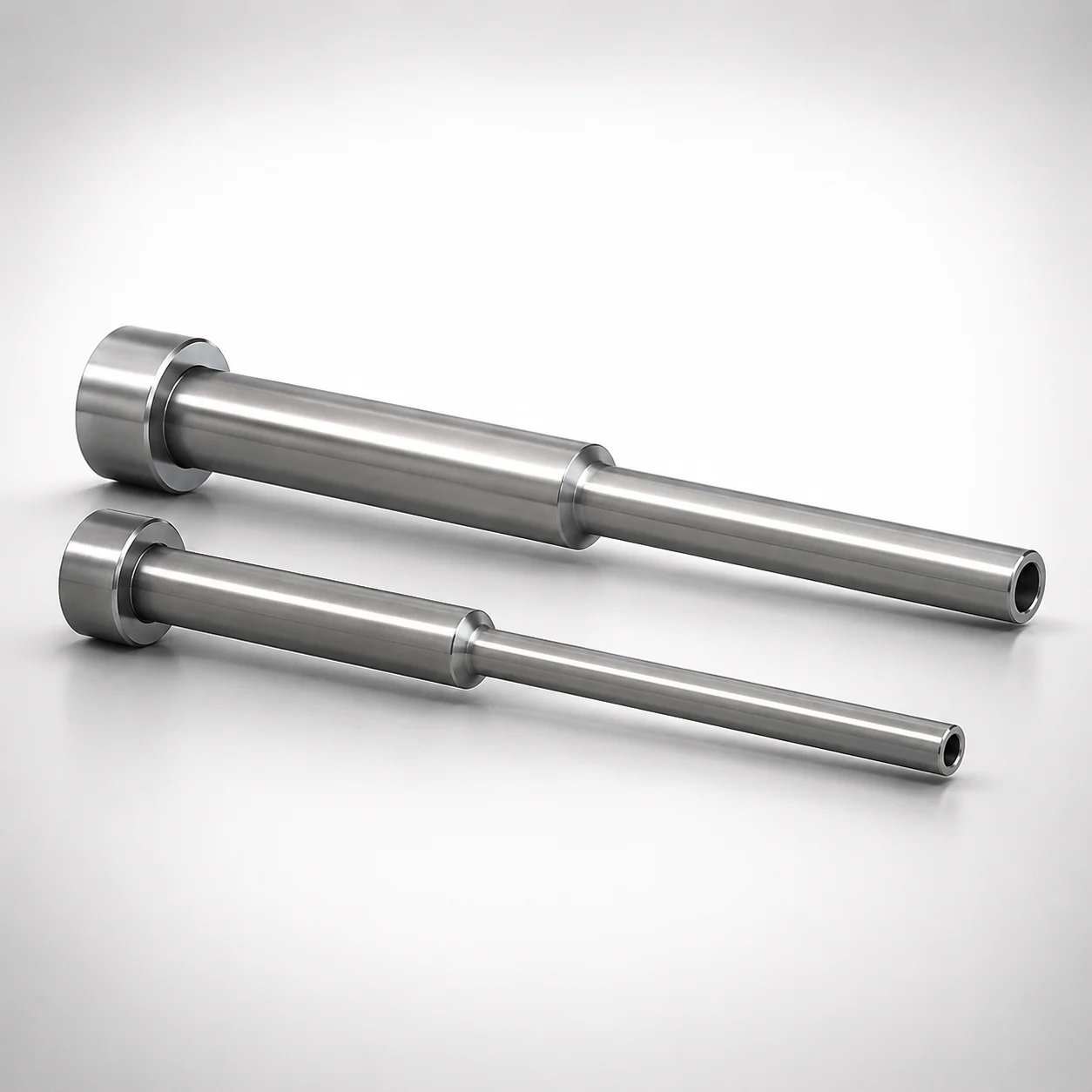
JIS Standard SKD61 Steel Stepped Ejector Sleeves
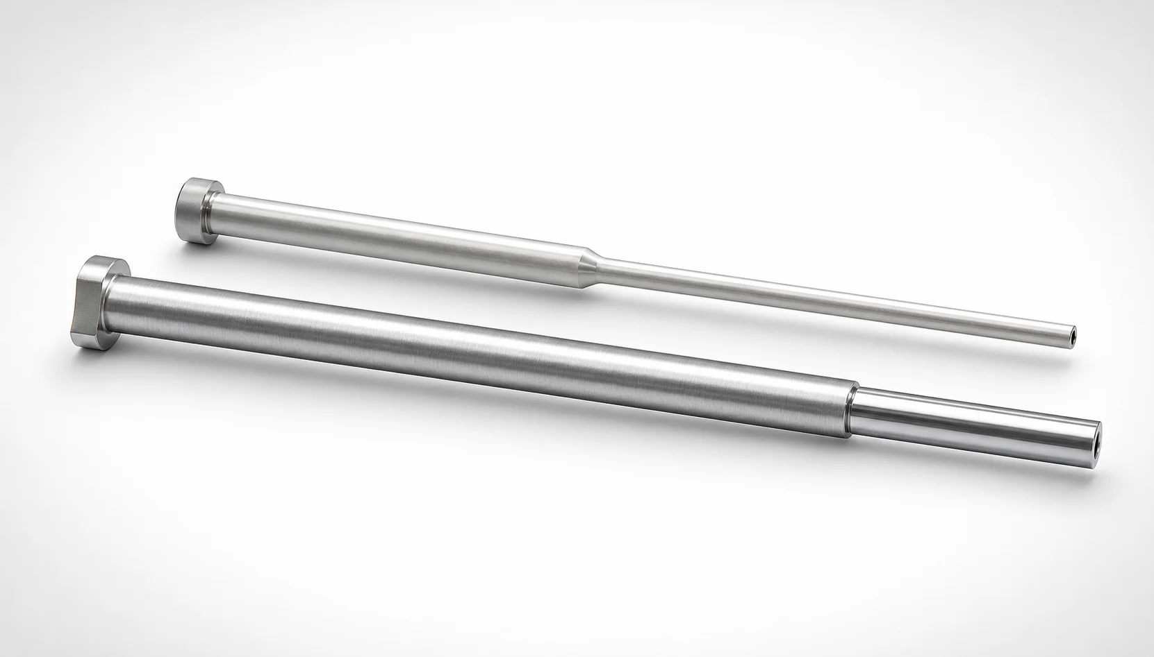
JIS Standard SKH51 Steel Precision Stepped Ejector Sleeves
Need Custom Specifications?
Our engineering team can help with custom configurations, material selection, and volume pricing.