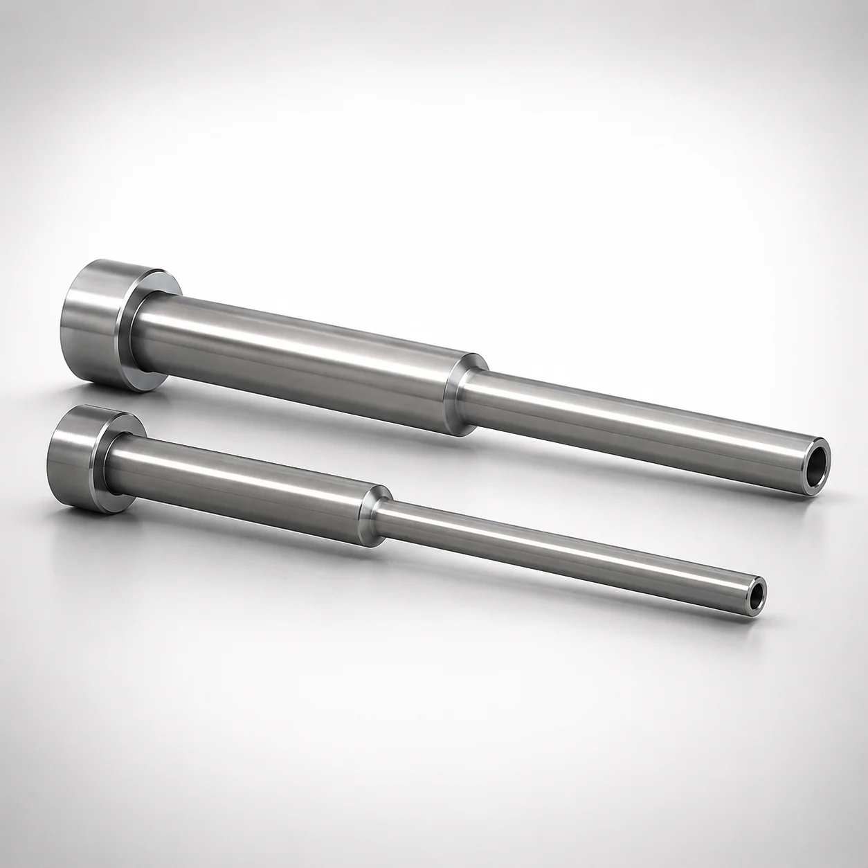
JIS Standard SKD61 Steel Stepped Ejector Sleeves
Stepped ejector sleeves (SKD61 steel) are built as a single-sleeve guidance component with a nitrided surface to improve wear resistance. The stepped geometry supports consistent centering and smooth ejector operation in production molds.
- Single-sleeve ESJF construction for stable fit in ejector systems
- Nitrided surface treatment helps reduce friction and scuffing during cycling
- Inner diameter tolerance H7 and tight shaft controls for reliable alignment
- Made to JIS head style for compatibility with standard mold designs
Specifications
34 configurations available
| Head Thickness | D (Shaft Diameter) (mm) | P (Tip Diameter) (mm) | V (Hole Diameter) (mm) | C (Recess diameter) (mm) | L (L dimension) (mm) | Dimension N (mm) | S (V hole diameter length) (mm) | type |
|---|---|---|---|---|---|---|---|---|
| 6mm(JIS) | 5 | 3.5 ~ 4.95 | 2 ~ 3 | 2.5 ~ 3.5 | 50 ~ 300 | 16 ~ 300 | 20 ~ 100 | - |
| 6mm(JIS) | 5.5 | 3.5 ~ 5.45 | 2 ~ 3.5 | 2.5 ~ 4 | 50 ~ 300 | 16 ~ 300 | 20 ~ 100 | - |
| 6mm(JIS) | 6 | 4 ~ 5.95 | 2 ~ 4 | 2.5 ~ 4.5 | 50 ~ 500 | 16 ~ 500 | 20 ~ 100 | - |
| 6mm(JIS) | 6 | 4 ~ 5.95 | 2 ~ 4 | 2.5 ~ 4.5 | 50 ~ 500 | 16 ~ 500 | 20 ~ 100 | - |
| 6mm(JIS) | 6.5 | 4 ~ 6.45 | 2 ~ 4.5 | 2.5 ~ 5 | 50 ~ 500 | 16 ~ 500 | 20 ~ 150 | - |
| 6mm(JIS) | 6.5 | 4 ~ 6.45 | 2 ~ 4.5 | 2.5 ~ 5 | 50 ~ 500 | 16 ~ 500 | 20 ~ 150 | - |
| 6mm(JIS) | 7 | 4 ~ 6.95 | 2 ~ 5 | 2.5 ~ 5.5 | 50 ~ 500 | 16 ~ 500 | 20 ~ 150 | - |
| 6mm(JIS) | 7 | 4 ~ 6.95 | 2 ~ 5 | 2.5 ~ 5.5 | 50 ~ 500 | 16 ~ 500 | 20 ~ 150 | - |
| 6mm(JIS) | 7.5 | 4 ~ 7.45 | 2 ~ 5.5 | 2.5 ~ 6 | 50 ~ 500 | 16 ~ 500 | 20 ~ 150 | - |
| 6mm(JIS) | 7.5 | 4 ~ 7.45 | 2 ~ 5.5 | 2.5 ~ 6 | 50 ~ 500 | 16 ~ 500 | 20 ~ 150 | - |
| 8mm(JIS) | 8 | 5 ~ 7.95 | 2.5 ~ 6 | 3 ~ 6.5 | 70 ~ 500 | 26 ~ 500 | 20 ~ 150 | - |
| 8mm(JIS) | 8 | 5 ~ 7.95 | 2.5 ~ 6 | 3 ~ 6.5 | 70 ~ 500 | 26 ~ 500 | 20 ~ 150 | - |
| 8mm(JIS) | 9 | 6 ~ 8.95 | 2.5 ~ 7 | 3 ~ 7.5 | 70 ~ 500 | 24 ~ 490 | 20 ~ 150 | - |
| 8mm(JIS) | 9 | 6 ~ 8.95 | 2.5 ~ 7 | 3 ~ 7.5 | 70 ~ 500 | 24 ~ 490 | 20 ~ 150 | - |
| 8mm(JIS) | 10 | 6 ~ 9.95 | 2.5 ~ 8 | 3 ~ 8.5 | 70 ~ 500 | 24 ~ 590 | 20 ~ 150 | - |
| 8mm(JIS) | 10 | 6 ~ 9.95 | 2.5 ~ 8 | 3 ~ 8.5 | 70 ~ 500 | 24 ~ 590 | 20 ~ 150 | - |
| 8mm(JIS) | 10 | 6 ~ 9.95 | 2.5 ~ 8 | 3 ~ 8.5 | 500.1 ~ 800 | 24 ~ 590 | 20 ~ 150 | - |
| 8mm(JIS) | 10 | 6 ~ 9.95 | 2.5 ~ 8 | 3 ~ 8.5 | 500.1 ~ 800 | 24 ~ 590 | 20 ~ 150 | - |
| 8mm(JIS) | 12 | 7.5 ~ 11.95 | 2.5 ~ 10 | 3 ~ 10.5 | 70 ~ 500 | 24 ~ 600 | 20 ~ 150 | - |
| 8mm(JIS) | 12 | 7.5 ~ 11.95 | 2.5 ~ 10 | 3 ~ 10.5 | 70 ~ 500 | 24 ~ 600 | 20 ~ 150 | - |
| 8mm(JIS) | 12 | 7.5 ~ 11.95 | 2.5 ~ 10 | 3 ~ 10.5 | 500.1 ~ 800 | 24 ~ 600 | 20 ~ 150 | - |
| 8mm(JIS) | 12 | 7.5 ~ 11.95 | 2.5 ~ 10 | 3 ~ 10.5 | 500.1 ~ 800 | 24 ~ 600 | 20 ~ 150 | - |
| 8mm(JIS) | 15 | 10 ~ 14.95 | 2.5 ~ 12 | 3 ~ 12.5 | 70 ~ 500 | 24 ~ 590 | 20 ~ 150 | - |
| 8mm(JIS) | 15 | 10 ~ 14.95 | 2.5 ~ 12 | 3 ~ 12.5 | 70 ~ 500 | 24 ~ 590 | 20 ~ 150 | - |
| 8mm(JIS) | 15 | 10 ~ 14.95 | 2.5 ~ 12 | 3 ~ 12.5 | 500.1 ~ 800 | 24 ~ 590 | 20 ~ 150 | - |
| 8mm(JIS) | 15 | 10 ~ 14.95 | 2.5 ~ 12 | 3 ~ 12.5 | 500.1 ~ 800 | 24 ~ 590 | 20 ~ 150 | - |
| 8mm(JIS) | 16 | 12 ~ 15.95 | 3 ~ 13 | 3.5 ~ 13.5 | 100 ~ 500 | 34 ~ 590 | 20 ~ 150 | - |
| 8mm(JIS) | 16 | 12 ~ 15.95 | 3 ~ 13 | 3.5 ~ 13.5 | 100 ~ 500 | 34 ~ 590 | 20 ~ 150 | - |
| 8mm(JIS) | 16 | 12 ~ 15.95 | 3 ~ 13 | 3.5 ~ 13.5 | 500.1 ~ 800 | 34 ~ 590 | 20 ~ 150 | - |
| 8mm(JIS) | 16 | 12 ~ 15.95 | 3 ~ 13 | 3.5 ~ 13.5 | 500.1 ~ 800 | 34 ~ 590 | 20 ~ 150 | - |
| 8mm(JIS) | 20 | 14.5 ~ 19.95 | 3 ~ 16 | 3.5 ~ 17 | 100 ~ 500 | 34 ~ 590 | 20 ~ 150 | - |
| 8mm(JIS) | 20 | 14.5 ~ 19.95 | 3 ~ 16 | 3.5 ~ 17 | 100 ~ 500 | 34 ~ 590 | 20 ~ 150 | - |
| 8mm(JIS) | 20 | 14.5 ~ 19.95 | 3 ~ 16 | 3.5 ~ 17 | 500.1 ~ 800 | 34 ~ 590 | 20 ~ 150 | - |
| 8mm(JIS) | 20 | 14.5 ~ 19.95 | 3 ~ 16 | 3.5 ~ 17 | 500.1 ~ 800 | 34 ~ 590 | 20 ~ 150 | - |
Product Guide
Application Scenarios+
Stepped ejector sleeves like this SKD61 guidance component are used in injection mold tooling where repeatable centering of ejector systems is critical. The stepped profile helps maintain alignment during the thrust-to-return cycle, reducing side load on ejector pins and promoting smooth ejection.
- Automotive connector and terminal molds: In high-cycle production, the nitrided surface lowers friction and scuffing risk, supporting stable guidance for ejector sleeves working with H7-controlled shaft fits.
- Appliance and electronics housings: When ejection forces vary across parts, the single-sleeve ESJF construction helps keep the ejector train centered, improving consistency and surface finish on the formed part.
- General industrial component molds: The JIS head style supports compatibility with standard mold layout conventions, helping designers integrate the sleeve into existing ejector assemblies.
Material & Process Details+
This product uses JIS Standard SKD61 steel, commonly equated to AISI H13 for hot-work die steel applications. Its purpose in ejector sleeve service is to balance toughness for cyclic loading with sufficient wear resistance at sliding interfaces.
- Nitrided surface finish: A nitrided layer is applied to improve surface hardness and reduce friction, helping limit scuffing during repeated ejection cycles.
- Heat treatment state: Nitriding is performed after the base steel is prepared to achieve the required core toughness; the surface treatment provides the primary wear benefit.
- Trade-off: SKD61/ H13-type steels favor impact toughness compared with higher-carbide wear steels, but rely on nitriding for maximum sliding wear performance.
Hardness values (HRC) are not provided in the supplied data, so they should be verified against the exact heat and nitriding spec used by the supplier.
Sizing & Selection Guide+
Select the stepped ejector sleeve dimensions by matching the ejector system’s guided shaft and the mold’s ejector head geometry. The shaft diameter D = 5 ~ 20 mm should correspond to the mating guided member, using the supplied inner diameter tolerance H7 to achieve the intended fit and alignment.
- Tip/hole interfacing: Choose P = 3.5 ~ 14.5 mm and V = 2 ~ 3 mm to reflect the local clearance and tip-to-hole relationship in your ejector layout.
- Recess/clearance features: Set C = 2.5 ~ 3.5 mm and the L length to match the sleeve’s working engagement zone. Available L ranges include 50–300, 50–500, 70–500, 500.1–800, and 100–500.
- Mounting geometry: Confirm Head thickness options of 6 mm (JIS) or 8 mm (JIS), and verify Dimension N = 16 ~ 34 mm plus S (V hole diameter length) = 20–100 or 20–150.
Because H7 is specified for the inner diameter, ensure your mating shaft tolerances and measurement datums align with the sleeve bore standard to maintain centering under load.
Frequently Asked Questions
What steel and surface treatment are used for these stepped ejector sleeves, and how does the nitriding affect wear during ejection cycles?+
How do I select the correct shaft diameter D, given the sleeve bore is specified as H7 tolerance?+
What stepped geometry dimensions should I verify to ensure stable centering in the ejector system?+
Are head thickness options available, and how do they affect integration into JIS-style mold ejector assemblies?+
What does ESJF type mean for ejector sleeve guidance stability?+
Related Products
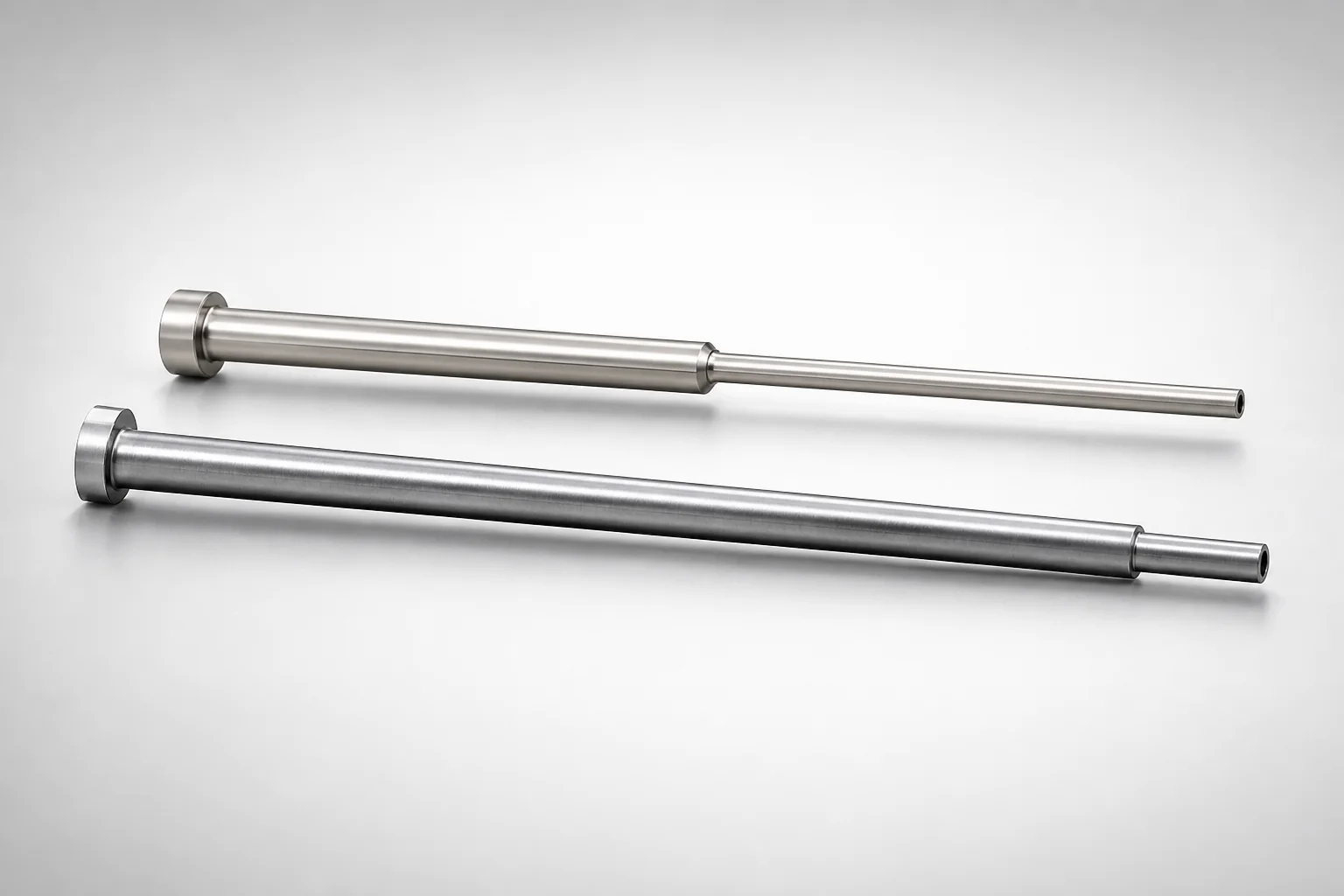
JIS Standard SKH51 Steel Precision Stepped Ejector Sleeves (ESVF)
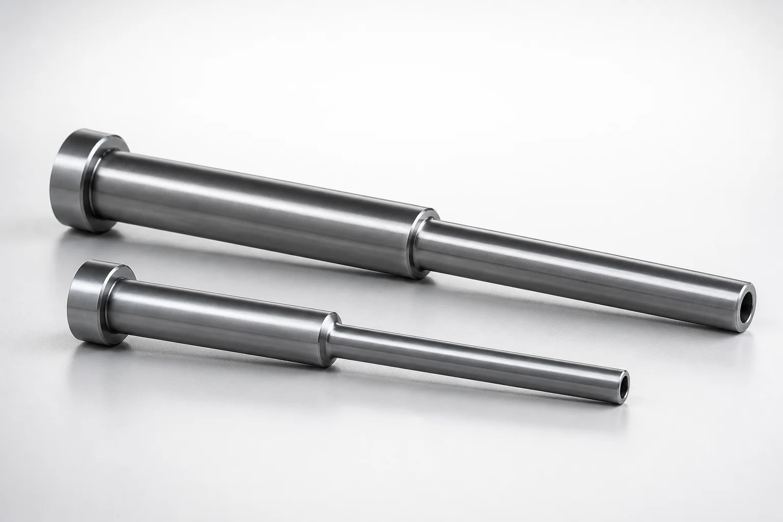
JIS Standard SKD61 Steel Stepped Ejector Sleeves
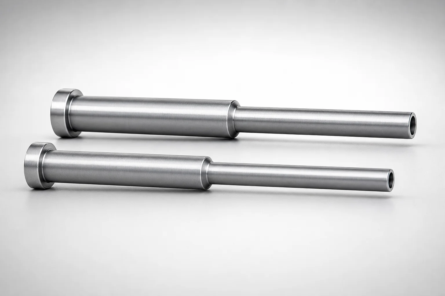
JIS Standard SKD61 Steel Stepped Ejector Sleeves
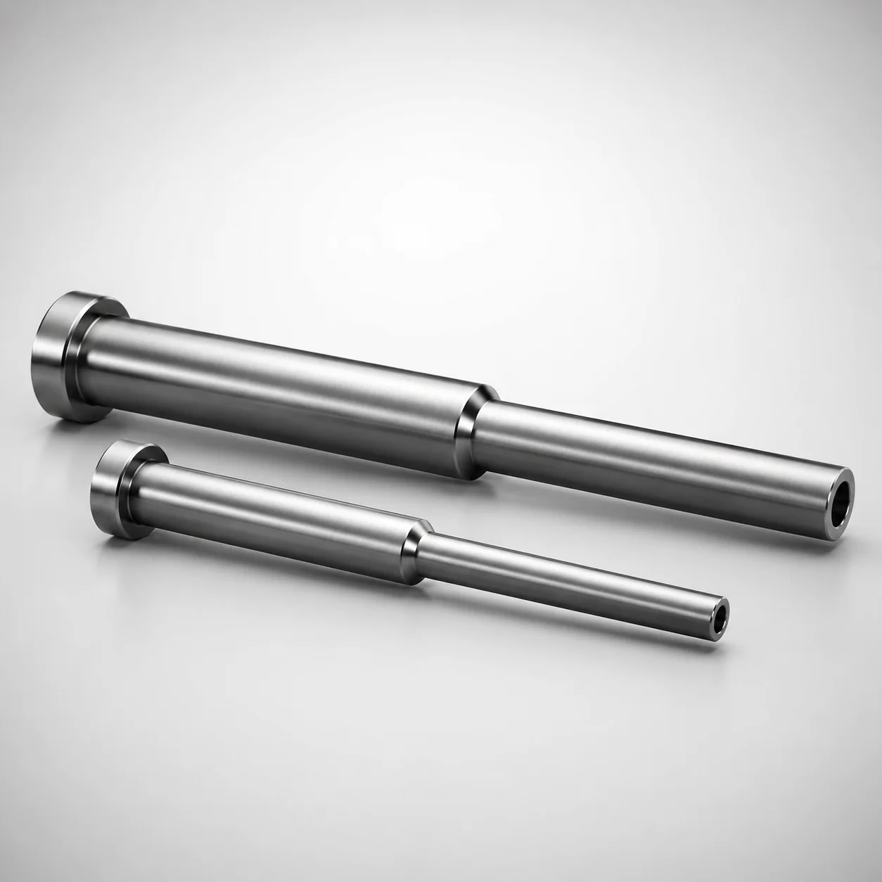
ESNF Type SKD61 Hardened Steel Stepped Ejector Sleeves
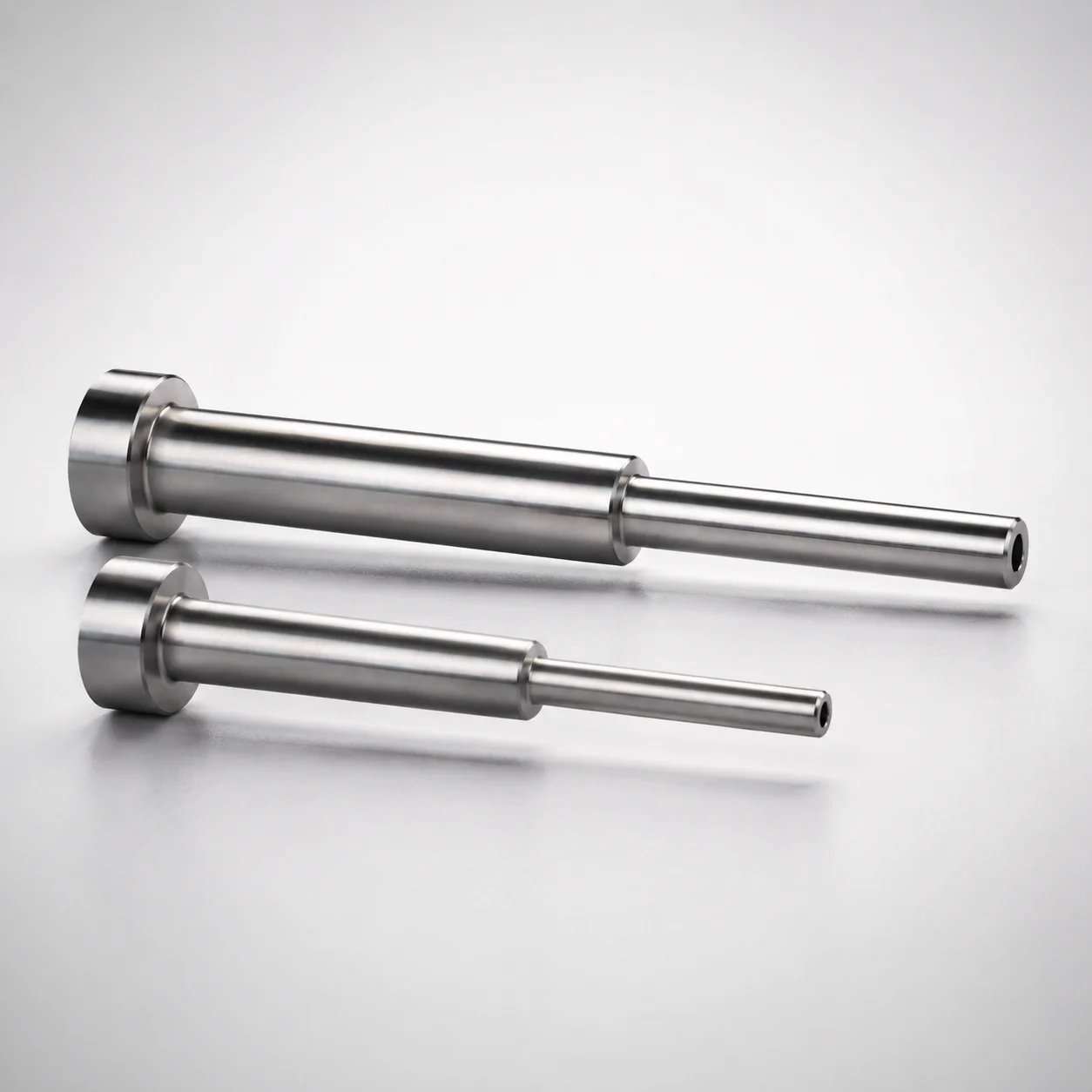
Japanese Standard SKD61 Steel Stepped Ejector Sleeves
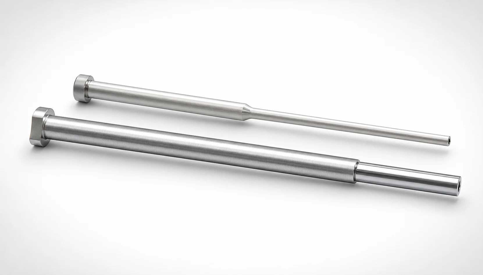
JIS Standard SKH51 Steel Precision Stepped Ejector Sleeves
Need Custom Specifications?
Our engineering team can help with custom configurations, material selection, and volume pricing.