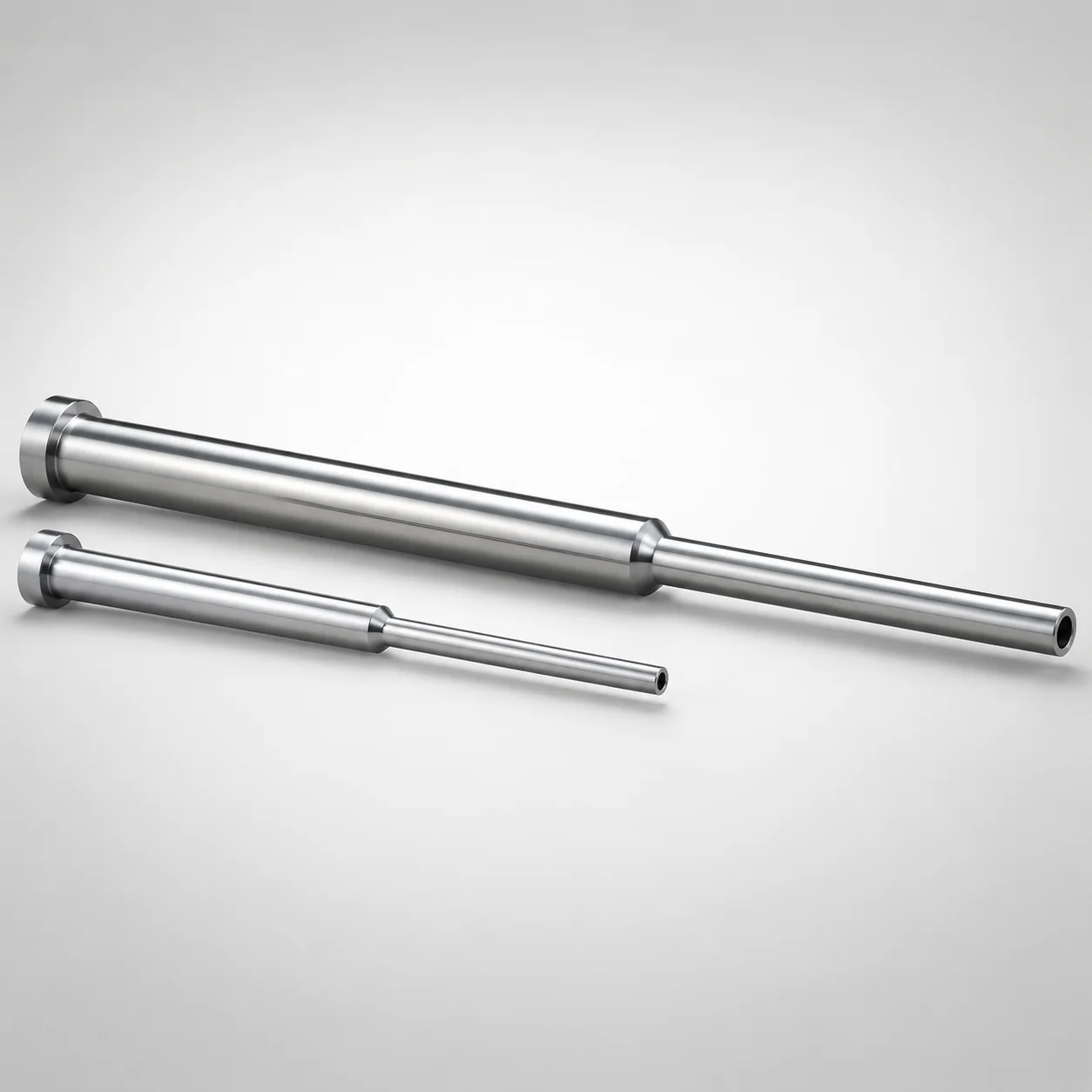
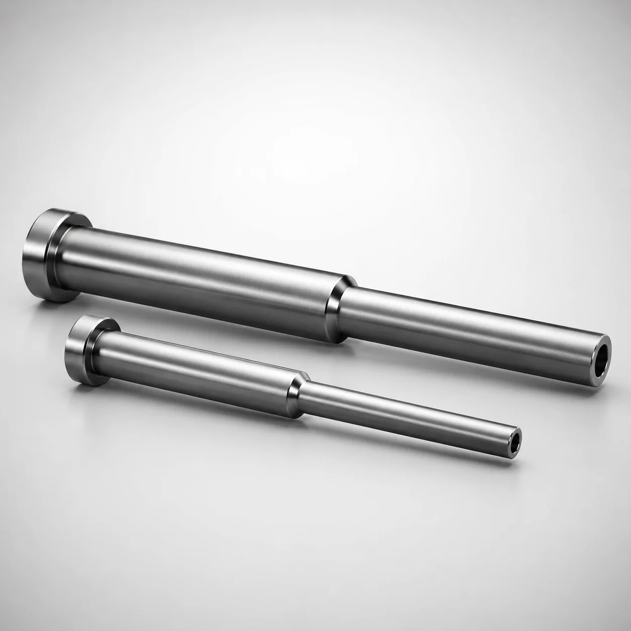
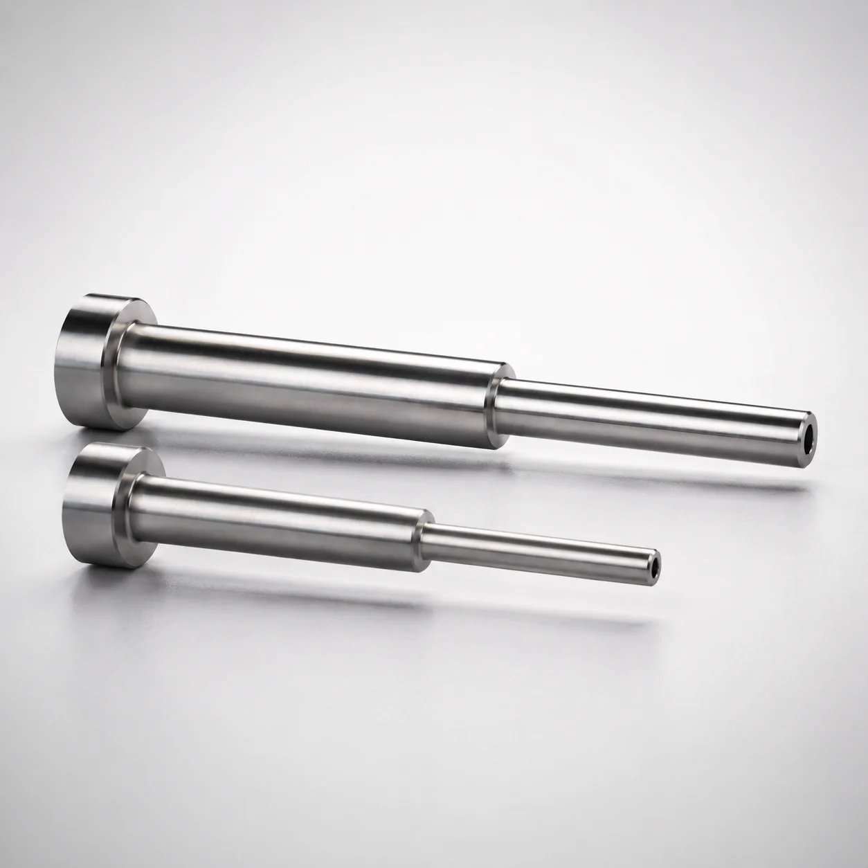
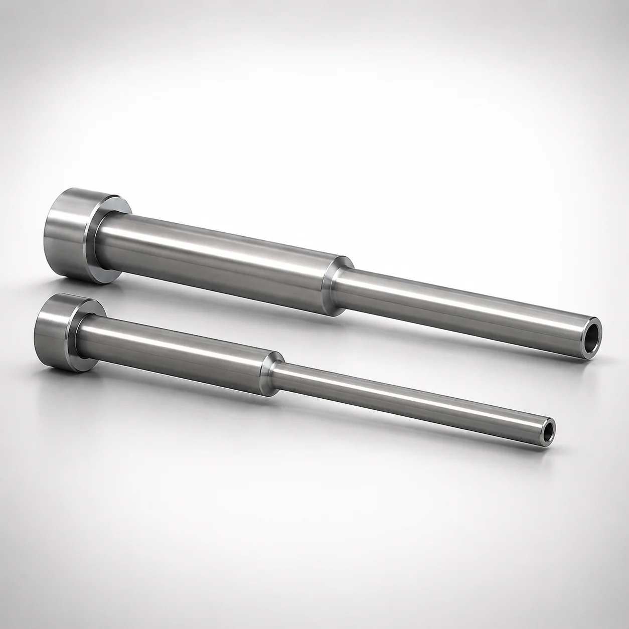
JIS Standard SKH51 Steel Precision Stepped Ejector Sleeves
Precision stepped ejector sleeves (SKH51 steel) provide a controlled, stepped guiding surface for reliable ejection while maintaining stable alignment in the mold. Ground boring supports smooth sliding performance across demanding production cycles.
- Single sleeve design with stepped form for consistent guiding and smooth ejection
- SKH51 steel construction with ground boring improves wear resistance and dimensional stability
- JIS specifications support repeatable assembly performance in precision tooling
- Configurable type options (ESVBF family) to match different sleeve hole and bearing arrangements
Specifications
42 configurations available
| Head Thickness | D (Shaft Diameter) (mm) | P (Tip Diameter) (mm) | V (Hole Diameter) (mm) | Concentricity | Inner Diameter Tolerance | Shaft Diameter Tolerance | L(L dimension) (mm) | Dimension N (mm) | S (V hole diameter length) (mm) | type |
|---|---|---|---|---|---|---|---|---|---|---|
| 4mm(T4) | 3.5 ~ 13 | 3.2 ~ 12.9 | 0.8 ~ 11.7 | ◎0.005 | +0.005/0 | 0/-0.005 | 40 ~ 250 | 20 ~ 240 | 1 ~ 25 | - |
| 4mm(T4) | 3.5 ~ 13 | 3.2 ~ 12.9 | 0.8 ~ 11.7 | ◎0.005 | +0.01/0 | -0.01/-0.02 | 40 ~ 250 | 20 ~ 240 | 1 ~ 25 | - |
| 4mm(T4) | 3.5 ~ 13 | 3.2 ~ 12.9 | 0.8 ~ 11.7 | ◎0.01 | +0.01/0 | -0.01/-0.02 | 40 ~ 250 | 20 ~ 240 | 1 ~ 25 | - |
| 4mm(T4) | 4 | 3.2 ~ 3.9 | 0.8 ~ 2.7 | ◎0.005 | +0.005/0 | 0/-0.005 | 40 ~ 225 | 20 ~ 215 | 1 ~ 8 | - |
| 4mm(T4) | 5 | 3.2 ~ 4.9 | 0.8 ~ 3.7 | ◎0.005 | +0.005/0 | 0/-0.005 | 40 ~ 225 | 20 ~ 215 | 1 ~ 11 | - |
| 4mm(T4) | 6 | 3.2 ~ 5.9 | 0.8 ~ 4.7 | ◎0.005 | +0.005/0 | 0/-0.005 | 40 ~ 225 | 20 ~ 215 | 1 ~ 23.5 | - |
| 4mm(T4) | 7 | 3.2 ~ 6.9 | 2 ~ 5.7 | ◎0.005 | +0.005/0 | 0/-0.005 | 40 ~ 250 | 20 ~ 240 | 1 ~ 17 | - |
| 4mm(T4) | 8 | 3.2 ~ 7.9 | 2 ~ 6.7 | ◎0.005 | +0.005/0 | 0/-0.005 | 40 ~ 250 | 20 ~ 240 | 1 ~ 20 | - |
| 4mm(T4) | 9 | 3.2 ~ 8.9 | 2 ~ 7.7 | ◎0.005 | +0.005/0 | 0/-0.005 | 40 ~ 250 | 20 ~ 240 | 1 ~ 23 | - |
| 4mm(T4) | 10 | 4.85 ~ 9.9 | 2 ~ 8.7 | ◎0.005 | +0.005/0 | 0/-0.005 | 40 ~ 250 | 20 ~ 240 | 1 ~ 25 | - |
| 4mm(T4) | 11 | 5.35 ~ 10.9 | 2 ~ 9.7 | ◎0.005 | +0.005/0 | 0/-0.005 | 40 ~ 250 | 20 ~ 240 | 1 ~ 25 | - |
| 4mm(T4) | 12 | 5.85 ~ 11.9 | 2 ~ 10.7 | ◎0.005 | +0.005/0 | 0/-0.005 | 40 ~ 250 | 20 ~ 240 | 1 ~ 25 | - |
| 4mm(T4) | 13 | 6.35 ~ 12.9 | 2 ~ 11.7 | ◎0.005 | +0.005/0 | 0/-0.005 | 40 ~ 250 | 20 ~ 240 | 1 ~ 25 | - |
| 4mm(T4) | 4 | 3.2 ~ 3.9 | 0.8 ~ 2.7 | ◎0.005 | +0.01/0 | -0.01/-0.02 | 40 ~ 225 | 20 ~ 215 | 1 ~ 13.5 | - |
| 4mm(T4) | 5 | 3.2 ~ 4.9 | 0.8 ~ 3.7 | ◎0.005 | +0.01/0 | -0.01/-0.02 | 40 ~ 225 | 20 ~ 215 | 1 ~ 18.5 | - |
| 4mm(T4) | 6 | 3.2 ~ 5.9 | 0.8 ~ 4.7 | ◎0.005 | +0.01/0 | -0.01/-0.02 | 40 ~ 225 | 20 ~ 215 | 1 ~ 23.5 | - |
| 4mm(T4) | 7 | 3.2 ~ 6.9 | 2 ~ 5.7 | ◎0.005 | +0.01/0 | -0.01/-0.02 | 40 ~ 250 | 20 ~ 240 | 1 ~ 25 | - |
| 4mm(T4) | 8 | 3.2 ~ 7.9 | 2 ~ 6.7 | ◎0.005 | +0.01/0 | -0.01/-0.02 | 40 ~ 250 | 20 ~ 240 | 1 ~ 25 | - |
| 4mm(T4) | 9 | 3.2 ~ 8.9 | 2 ~ 7.7 | ◎0.005 | +0.01/0 | -0.01/-0.02 | 40 ~ 250 | 20 ~ 240 | 1 ~ 25 | - |
| 4mm(T4) | 10 | 4.85 ~ 9.9 | 2 ~ 8.7 | ◎0.005 | +0.01/0 | -0.01/-0.02 | 40 ~ 250 | 20 ~ 240 | 1 ~ 25 | - |
| 4mm(T4) | 11 | 5.35 ~ 10.9 | 2 ~ 9.7 | ◎0.005 | +0.01/0 | -0.01/-0.02 | 40 ~ 250 | 20 ~ 240 | 1 ~ 25 | - |
| 4mm(T4) | 12 | 5.85 ~ 11.9 | 2 ~ 10.7 | ◎0.005 | +0.01/0 | -0.01/-0.02 | 40 ~ 250 | 20 ~ 240 | 1 ~ 25 | - |
| 4mm(T4) | 13 | 6.35 ~ 12.9 | 2 ~ 11.7 | ◎0.005 | +0.01/0 | -0.01/-0.02 | 40 ~ 250 | 20 ~ 240 | 1 ~ 25 | - |
| 4mm(T4) | 4 | 3.2 ~ 3.9 | 0.8 ~ 2.7 | ◎0.01 | +0.01/0 | -0.01/-0.02 | 40 ~ 225 | 20 ~ 215 | 1 ~ 13.5 | - |
| 4mm(T4) | 5 | 3.2 ~ 4.9 | 0.8 ~ 3.7 | ◎0.01 | +0.01/0 | -0.01/-0.02 | 40 ~ 225 | 20 ~ 215 | 1 ~ 18.5 | - |
| 4mm(T4) | 6 | 3.2 ~ 5.9 | 0.8 ~ 4.7 | ◎0.01 | +0.01/0 | -0.01/-0.02 | 40 ~ 225 | 20 ~ 215 | 1 ~ 23.5 | - |
| 4mm(T4) | 7 | 3.2 ~ 6.9 | 2 ~ 5.7 | ◎0.01 | +0.01/0 | -0.01/-0.02 | 40 ~ 250 | 20 ~ 240 | 1 ~ 25 | - |
| 4mm(T4) | 8 | 3.2 ~ 7.9 | 2 ~ 6.7 | ◎0.01 | +0.01/0 | -0.01/-0.02 | 40 ~ 250 | 20 ~ 240 | 1 ~ 25 | - |
| 4mm(T4) | 9 | 3.2 ~ 8.9 | 2 ~ 7.7 | ◎0.01 | +0.01/0 | -0.01/-0.02 | 40 ~ 250 | 20 ~ 240 | 1 ~ 25 | - |
| 4mm(T4) | 10 | 4.85 ~ 9.9 | 2 ~ 8.7 | ◎0.01 | +0.01/0 | -0.01/-0.02 | 40 ~ 250 | 20 ~ 240 | 1 ~ 25 | - |
| 4mm(T4) | 11 | 5.35 ~ 10.9 | 2 ~ 9.7 | ◎0.01 | +0.01/0 | -0.01/-0.02 | 40 ~ 250 | 20 ~ 240 | 1 ~ 25 | - |
| 4mm(T4) | 12 | 5.85 ~ 11.9 | 2 ~ 10.7 | ◎0.01 | +0.01/0 | -0.01/-0.02 | 40 ~ 250 | 20 ~ 240 | 1 ~ 25 | - |
| 4mm(T4) | 13 | 6.35 ~ 12.9 | 2 ~ 11.7 | ◎0.01 | +0.01/0 | -0.01/-0.02 | 40 ~ 250 | 20 ~ 240 | 1 ~ 25 | - |
| - | 5.1 ~ 13 | 3.2 ~ 12.9 | 0.8 ~ 11.7 | ◎0.005 | +0.005/0 | 0/-0.005 | 40 ~ 250 | 20 ~ 240 | 1 ~ 25 | - |
| 6mm(JIS) | 6 | 3.2 ~ 5.9 | 0.8 ~ 4.7 | ◎0.005 | +0.005/0 | 0/-0.005 | 40 ~ 225 | 20 ~ 215 | 1 ~ 14 | - |
| 6mm(JIS) | 7 | 3.2 ~ 6.9 | 2 ~ 5.7 | ◎0.005 | +0.005/0 | 0/-0.005 | 40 ~ 250 | 20 ~ 240 | 1 ~ 17 | - |
| 8mm(JIS) | 8 | 3.2 ~ 7.9 | 2 ~ 6.7 | ◎0.005 | +0.005/0 | 0/-0.005 | 40 ~ 250 | 20 ~ 240 | 1 ~ 20 | - |
| 8mm(JIS) | 9 | 3.2 ~ 8.9 | 2 ~ 7.7 | ◎0.005 | +0.005/0 | 0/-0.005 | 40 ~ 250 | 20 ~ 240 | 1 ~ 23 | - |
| 8mm(JIS) | 10 | 4.85 ~ 9.9 | 2 ~ 8.7 | ◎0.005 | +0.005/0 | 0/-0.005 | 40 ~ 250 | 20 ~ 240 | 1 ~ 25 | - |
| 8mm(JIS) | 11 | 5.35 ~ 10.9 | 2 ~ 9.7 | ◎0.005 | +0.005/0 | 0/-0.005 | 40 ~ 250 | 20 ~ 240 | 1 ~ 25 | - |
| 8mm(JIS) | 12 | 5.85 ~ 11.9 | 2 ~ 10.7 | ◎0.005 | +0.005/0 | 0/-0.005 | 40 ~ 250 | 20 ~ 240 | 1 ~ 25 | - |
| 8mm(JIS) | 13 | 6.35 ~ 12.9 | 2 ~ 11.7 | ◎0.005 | +0.005/0 | 0/-0.005 | 40 ~ 250 | 20 ~ 240 | 1 ~ 25 | - |
Product Guide
Application Scenarios+
Precision stepped ejector sleeves are used inside injection molds to provide controlled, stepped guidance for ejector pins, improving alignment during high-cycle ejection. The ground-bored bore helps the sleeve slide smoothly while maintaining stable positioning, which is critical where repeated stroke-to-stroke accuracy impacts part geometry.
- Automotive and appliance connector molds: Multi-feature connector housings often require consistent ejection of fine ribs and snap-fit areas. A precision sleeve with stable guiding reduces side-load on ejector pins and supports uniform part release.
- Medical device and diagnostic device housings: Thin-walled components demand careful control of ejection force to avoid surface marking. The stepped form supports predictable pin alignment and reduced wobble during ejection.
- Electronics enclosure tooling: For cavities with strict positional requirements, the sleeve’s concentricity (up to ◎0.005 or ◎0.01) and bore tolerance options help maintain concentric guiding around the ejector interface.
Configured to the ESVBF family options, this variant is suited for molds that benefit from ground boring for dimensional stability and reliable sliding performance.
Material & Process Details+
JIS Standard SKH51 is a precision steel grade commonly selected for wear-critical sliding components in mold tooling. Compared with general-purpose tool steels, SKH51 is chosen for its balance of hardness and wear resistance, supporting longer service life under repetitive ejector movement.
- Wear resistance vs. toughness: The harder, wear-focused character helps resist abrasion at the guiding surfaces, while still maintaining adequate toughness for typical ejector sleeve loads.
- Heat treatment state: The product is specified as SKH51 steel for precision stepped ejector sleeves; final hardness and performance are achieved through standard hardening/tempering practices used for SKH51 in mold component production.
- Manufacturing process: The sleeve includes ground boring, which improves dimensional stability and sliding fit by finishing the bore to a controlled geometry.
In comparison to softer steels, SKH51’s wear resistance makes it more suitable where guiding surfaces experience frequent contact and potential micro-abrasion during production.
Sizing & Selection Guide+
Select sleeve dimensions by matching the ejector guide interface to your mold’s core/cavity requirements. Use D (shaft diameter) 3.5–13 mm to fit the ejector pin/shaft, and then verify the P (tip diameter) 3.2–6.35 mm matches the stepped region that interfaces with your ejector geometry.
- Choose the bore/hole sizes: For internal fit and clearance, confirm V (hole diameter) 0.8–2 mm and the hole location dimension S = 1 mm (as specified).
- Check accuracy and concentricity targets: Available concentricity options are ◎0.005 or ◎0.01, and the inner diameter tolerance is +0.005/0 or +0.01/0. Shaft diameter tolerance is provided as 0/−0.005 or −0.01/−0.02, so confirm your pin tolerance stack-up.
- Match length to stroke space: Standard L = 40–250 mm (also available as 40–225 in the parameter set) and Dimension N = 20–240 mm (or 20–215). Ensure length accommodates your mold layout without binding.
Head thickness is configurable at T4 = 4 mm or JIS options 6 mm and 8 mm, which should align with your retainer/support thickness.
Frequently Asked Questions
Which shaft diameter range (D) is supported for this stepped ejector sleeve, and how do I confirm fit in my mold?+
What concentricity and inner diameter tolerance options are available, and why do they matter for guiding?+
How do I select the stepped tip diameter (P) and the hole diameter (V) for my ejector geometry?+
What length options (L and N) should I use to avoid interference or binding during ejection?+
Is this sleeve only for SKH51, and what does ground boring imply for performance?+
Related Products
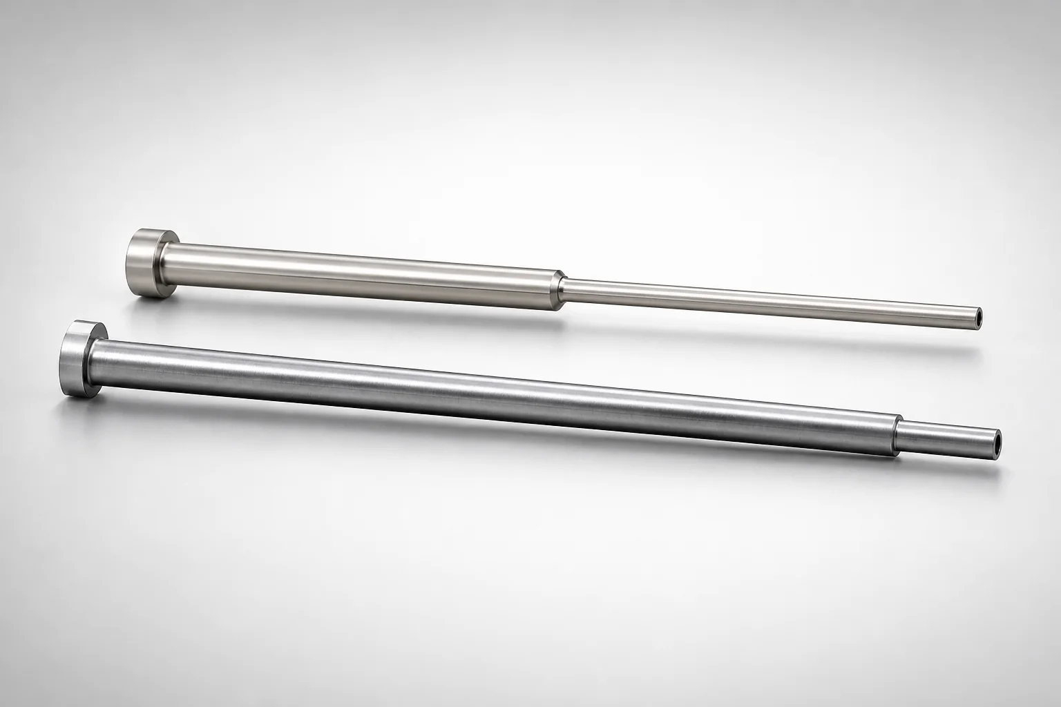
JIS Standard SKH51 Steel Precision Stepped Ejector Sleeves (ESVF)
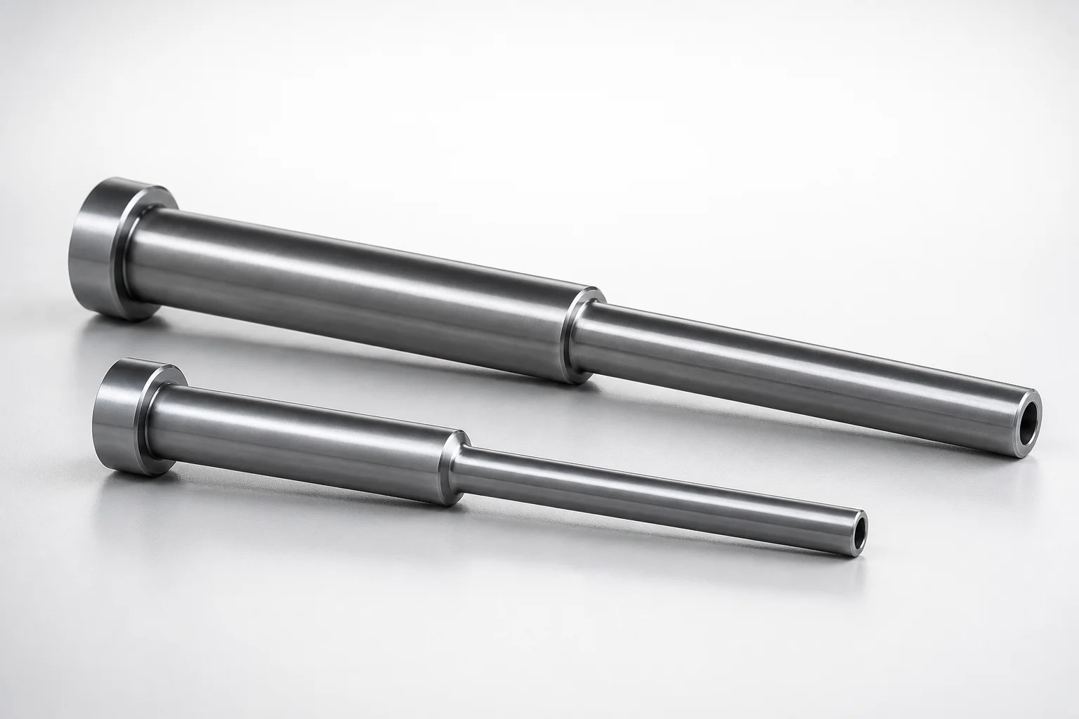
JIS Standard SKD61 Steel Stepped Ejector Sleeves
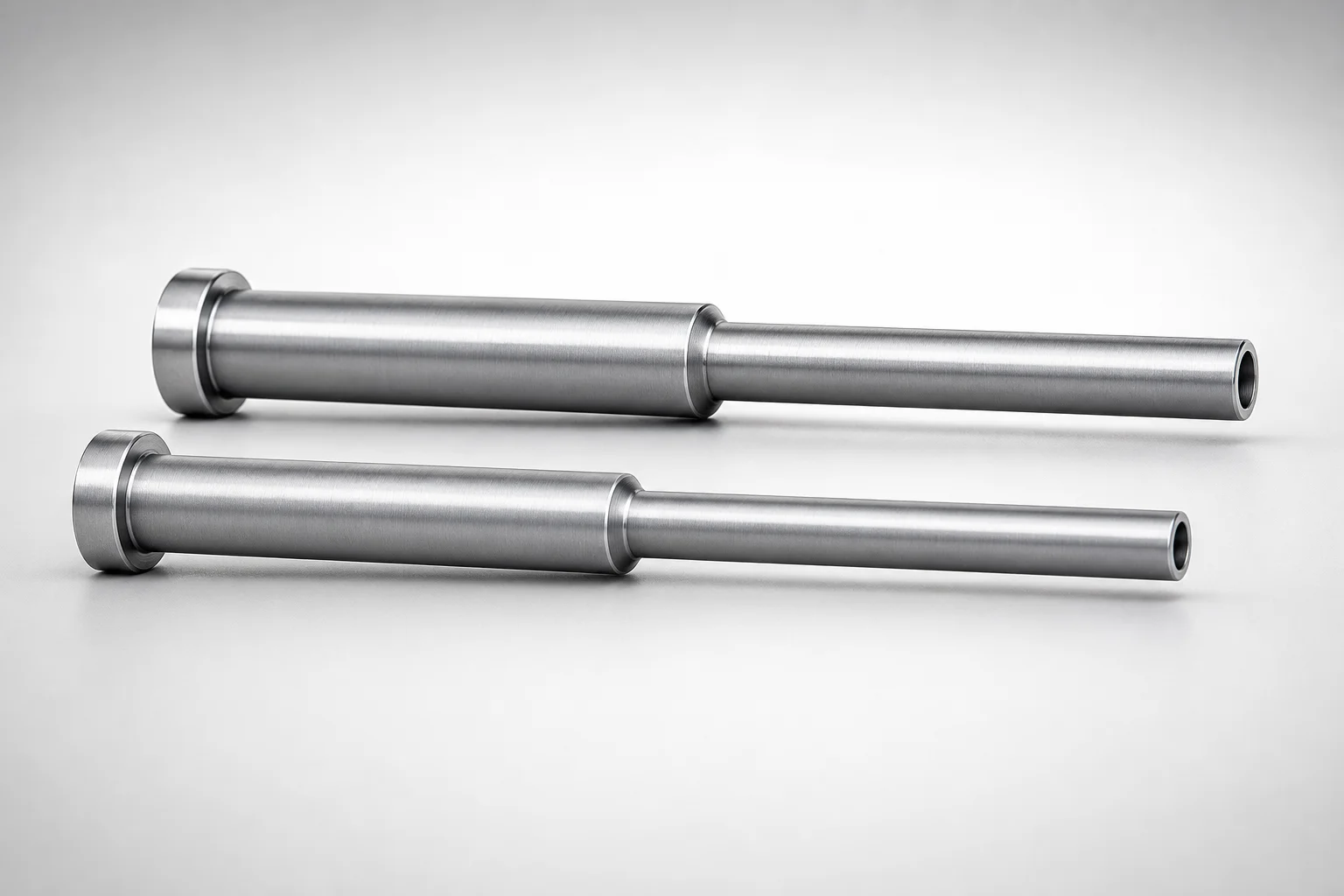
JIS Standard SKD61 Steel Stepped Ejector Sleeves
ESNF Type SKD61 Hardened Steel Stepped Ejector Sleeves
Japanese Standard SKD61 Steel Stepped Ejector Sleeves
JIS Standard SKD61 Steel Stepped Ejector Sleeves
Need Custom Specifications?
Our engineering team can help with custom configurations, material selection, and volume pricing.