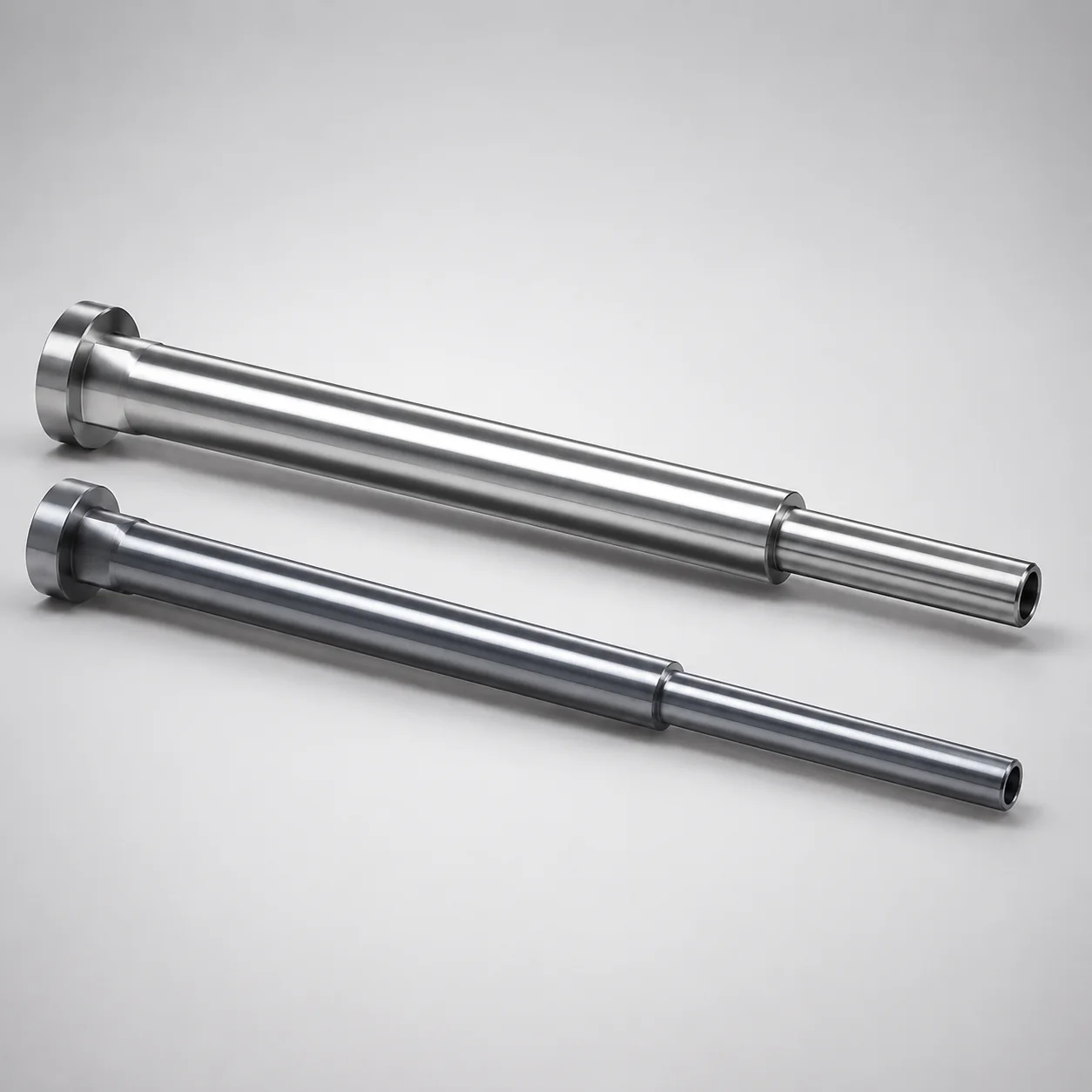
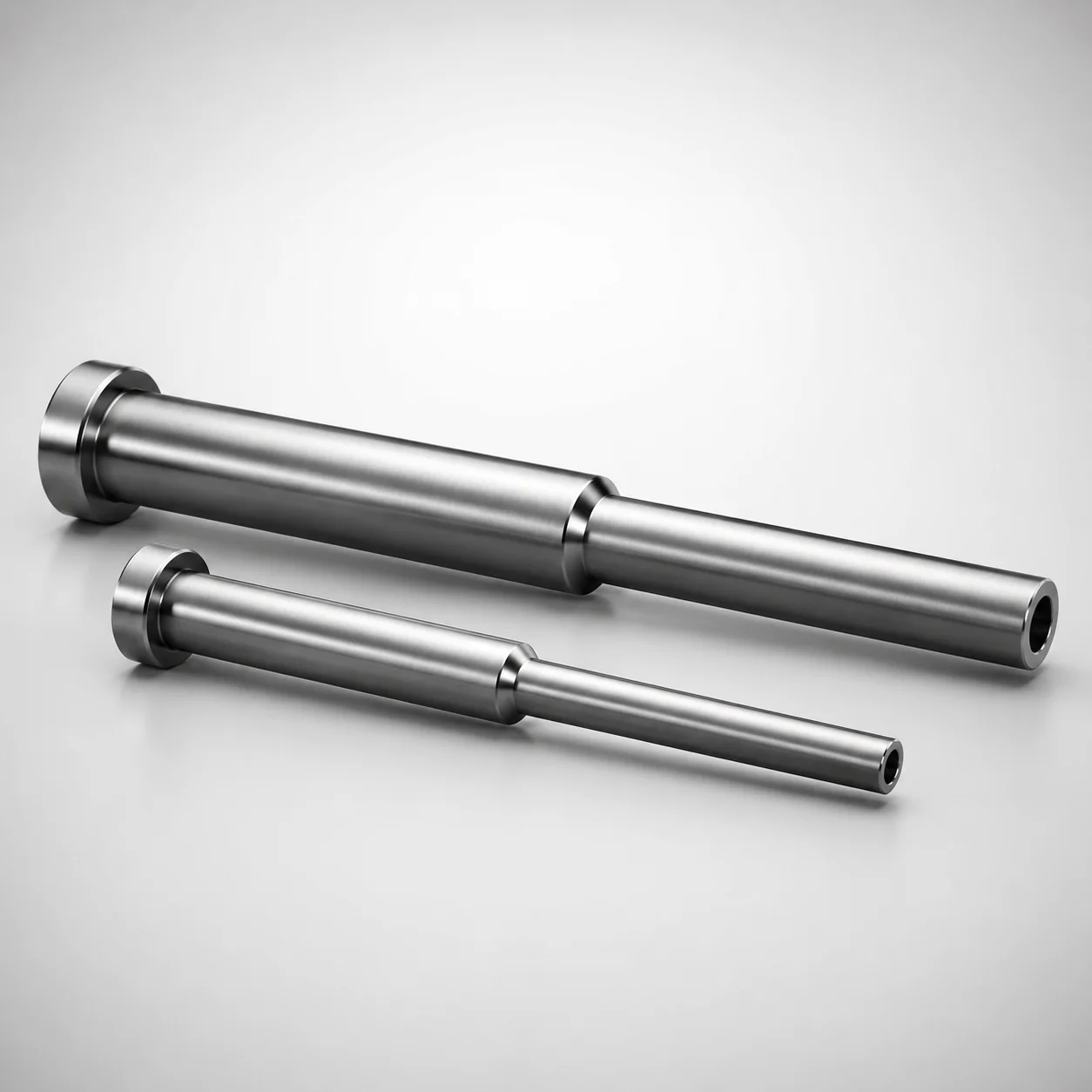
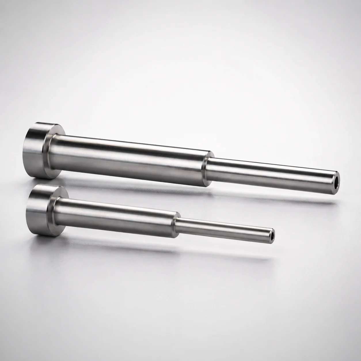
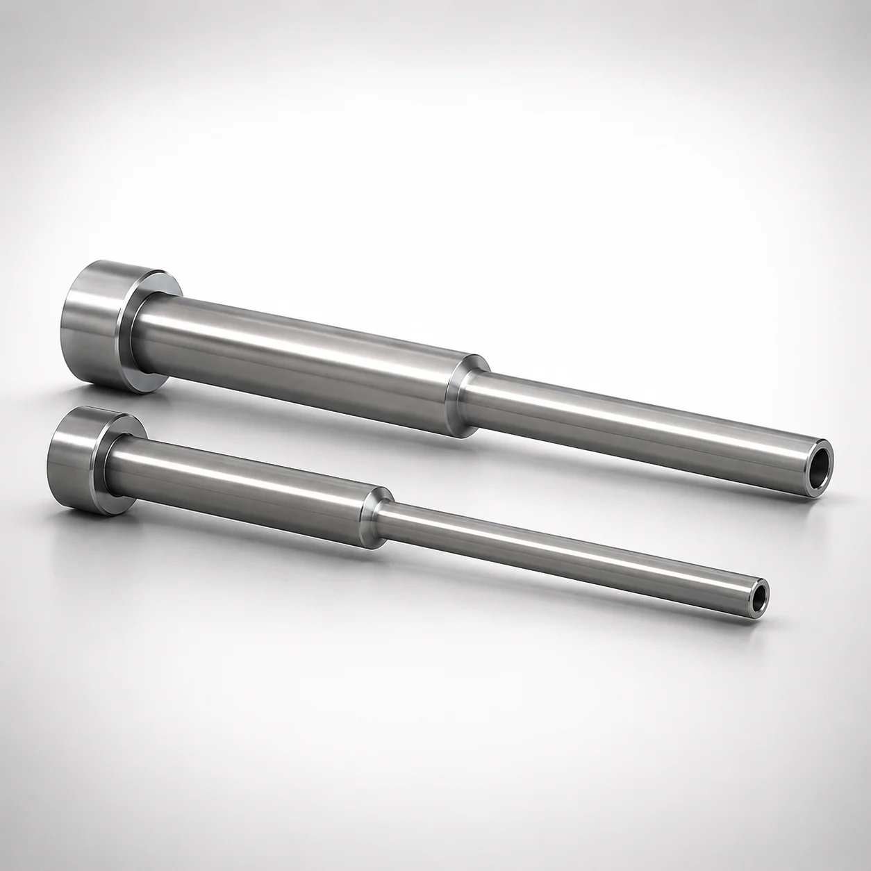
JIS Standard M2 Steel Precision Stepped Ejector Sleeves
Precision stepped ejector sleeves (M2 steel) are engineered for stable guidance and reliable fit in mold ejector systems, using a wire-cut and polished boring process for consistent internal geometry.
- Stepped sleeve design supports controlled alignment and smooth ejector operation
- SKH51 steel construction with wear-focused boring preparation
- Concentricity specified at 0.01 for predictable assembly performance
- Made to JIS requirements and suitable for precision die tooling
Specifications
33 configurations available
| Head Thickness | D (Shaft Diameter) (mm) | P (Tip Diameter) (mm) | V (Hole Diameter) (mm) | Shaft Diameter Tolerance | L(L dimension) (mm) | Dimension N (mm) | S (V hole diameter length) (mm) | type |
|---|---|---|---|---|---|---|---|---|
| 4mm(T4) | 3.5 ~ 13 | 3.2 ~ 12.9 | 0.8 ~ 11.7 | -0.01/-0.02 | 40 ~ 250 | 20 ~ 215 | 1 ~ 50 | - |
| 4mm(T4) | 3.5 ~ 13 | 3.2 ~ 12.9 | 0.8 ~ 11.7 | -0.01/-0.02 | 40 ~ 250 | 20 ~ 240 | 1 ~ 50 | - |
| 4mm(T4) | 3.5 | 3.2 ~ 3.4 | 0.8 ~ 2.2 | -0.01/-0.02 | 40 ~ 125 | 20 ~ 115 | 1 ~ 22 | - |
| 4mm(T4) | 4 | 3.2 ~ 3.9 | 0.8 ~ 2.7 | -0.01/-0.02 | 40 ~ 175 | 20 ~ 165 | 1 ~ 27 | - |
| 4mm(T4) | 5 | 3.2 ~ 4.9 | 0.8 ~ 3.7 | -0.01/-0.02 | 40 ~ 175 | 20 ~ 165 | 1 ~ 37 | - |
| 4mm(T4) | 6 | 3.2 ~ 5.9 | 0.8 ~ 4.7 | -0.01/-0.02 | 40 ~ 175 | 20 ~ 165 | 1 ~ 47 | - |
| 4mm(T4) | 7 | 3.2 ~ 6.9 | 2 ~ 5.7 | -0.01/-0.02 | 40 ~ 250 | 20 ~ 240 | 1 ~ 50 | - |
| 4mm(T4) | 8 | 3.2 ~ 7.9 | 2 ~ 6.7 | -0.01/-0.02 | 40 ~ 250 | 20 ~ 240 | 1 ~ 50 | - |
| 4mm(T4) | 9 | 3.2 ~ 8.9 | 2 ~ 7.7 | -0.01/-0.02 | 40 ~ 250 | 20 ~ 240 | 1 ~ 50 | - |
| 4mm(T4) | 10 | 4.85 ~ 9.9 | 2 ~ 8.7 | -0.01/-0.02 | 40 ~ 250 | 20 ~ 240 | 1 ~ 50 | - |
| 4mm(T4) | 11 | 5.35 ~ 10.9 | 2 ~ 9.7 | -0.01/-0.02 | 40 ~ 250 | 20 ~ 240 | 1 ~ 50 | - |
| 4mm(T4) | 12 | 5.85 ~ 11.9 | 2 ~ 10.7 | -0.01/-0.02 | 40 ~ 250 | 20 ~ 240 | 1 ~ 50 | - |
| 4mm(T4) | 13 | 6.35 ~ 12.9 | 2 ~ 11.7 | -0.01/-0.02 | 40 ~ 250 | 20 ~ 240 | 1 ~ 50 | - |
| 4mm(T4) | 3.5 | 3.2 ~ 3.4 | 0.8 ~ 2.2 | -0.01/-0.02 | 40 ~ 125 | 20 ~ 115 | 1 ~ 22 | - |
| 4mm(T4) | 4 | 3.2 ~ 3.9 | 0.8 ~ 2.7 | -0.01/-0.02 | 40 ~ 175 | 20 ~ 165 | 1 ~ 27 | - |
| 4mm(T4) | 5 | 3.2 ~ 4.9 | 0.8 ~ 3.7 | -0.01/-0.02 | 40 ~ 175 | 20 ~ 165 | 1 ~ 37 | - |
| 4mm(T4) | 6 | 3.2 ~ 5.9 | 0.8 ~ 4.7 | -0.01/-0.02 | 40 ~ 175 | 20 ~ 165 | 1 ~ 47 | - |
| 4mm(T4) | 7 | 3.2 ~ 6.9 | 2 ~ 5.7 | -0.01/-0.02 | 40 ~ 250 | 20 ~ 240 | 1 ~ 50 | - |
| 4mm(T4) | 8 | 3.2 ~ 7.9 | 2 ~ 6.7 | -0.01/-0.02 | 40 ~ 250 | 20 ~ 240 | 1 ~ 50 | - |
| 4mm(T4) | 9 | 3.2 ~ 8.9 | 2 ~ 7.7 | -0.01/-0.02 | 40 ~ 250 | 20 ~ 240 | 1 ~ 50 | - |
| 4mm(T4) | 10 | 4.85 ~ 9.9 | 2 ~ 8.7 | -0.01/-0.02 | 40 ~ 250 | 20 ~ 240 | 1 ~ 50 | - |
| 4mm(T4) | 11 | 5.35 ~ 10.9 | 2 ~ 9.7 | -0.01/-0.02 | 40 ~ 250 | 20 ~ 240 | 1 ~ 50 | - |
| 4mm(T4) | 12 | 5.85 ~ 11.9 | 2 ~ 10.7 | -0.01/-0.02 | 40 ~ 250 | 20 ~ 240 | 1 ~ 50 | - |
| 4mm(T4) | 13 | 6.35 ~ 12.9 | 2 ~ 11.7 | -0.01/-0.02 | 40 ~ 250 | 20 ~ 240 | 1 ~ 50 | - |
| - | 5.1 ~ 13 | 3.2 ~ 12.9 | 0.8 ~ 11.3 | 0/-0.005 | 40 ~ 250 | 20 ~ 240 | 1 ~ 50 | - |
| 6mm(JIS) | 6 | 3.2 ~ 5.9 | 0.8 ~ 4.7 | 0/-0.005 | 40 ~ 175 | 20 ~ 165 | 1 ~ 47 | - |
| 6mm(JIS) | 7 | 3.2 ~ 6.9 | 2 ~ 5.7 | 0/-0.005 | 40 ~ 250 | 20 ~ 240 | 1 ~ 50 | - |
| 8mm(JIS) | 8 | 3.2 ~ 7.9 | 2 ~ 6.7 | 0/-0.005 | 40 ~ 250 | 20 ~ 240 | 1 ~ 50 | - |
| 8mm(JIS) | 9 | 3.2 ~ 8.9 | 2 ~ 7.7 | 0/-0.005 | 40 ~ 250 | 20 ~ 240 | 1 ~ 50 | - |
| 8mm(JIS) | 10 | 4.85 ~ 9.9 | 2 ~ 8.7 | 0/-0.005 | 40 ~ 250 | 20 ~ 240 | 1 ~ 50 | - |
| 8mm(JIS) | 11 | 5.35 ~ 10.9 | 2 ~ 9.7 | 0/-0.005 | 40 ~ 250 | 20 ~ 240 | 1 ~ 50 | - |
| 8mm(JIS) | 12 | 5.85 ~ 11.9 | 2 ~ 10.7 | 0/-0.005 | 40 ~ 250 | 20 ~ 240 | 1 ~ 50 | - |
| 8mm(JIS) | 13 | 6.35 ~ 12.9 | 2 ~ 11.7 | 0/-0.005 | 40 ~ 250 | 20 ~ 240 | 1 ~ 50 | - |
Product Guide
Application Scenarios+
These precision stepped ejector sleeves are used as guiding components in injection molds where ejector concentricity directly affects smooth stroke, reduced wear, and stable part release. The wire-cut and polished boring internal geometry helps maintain controlled hole form, which is critical in high-cycle mold assemblies.
- Automotive connector and housing molds: Apply them in ejector systems to stabilize multi-pin or stepped ejector members during demolding, supporting consistent alignment even under repeated impact loading.
- Consumer electronics back covers and appliance housings: Use in molds that require tight assembly concentricity to prevent friction, chatter, and uneven ejector clearance—particularly when using stepped ejector designs.
- Precision die tooling and small mechanical parts: The sleeve’s stepped design and 0.01 concentricity specification make it suitable where guidance accuracy and repeatability are prioritized.
The M2 steel selection and precision boring process make this variant well-suited for long-running tooling that needs both wear resistance and controlled guidance.
Material & Process Details+
This product is specified in SKH51 M2-type steel, an HSS family grade commonly associated with AISI M2 equivalent performance for hardness-retentive cutting and wear conditions. The key value for ejector sleeves is wear resistance in sliding contact and guidance surfaces, while maintaining sufficient toughness for normal demolding forces.
- Hardness/structure: Typically delivered in a hardened condition suitable for precision sliding components; final hardness depends on the supplier’s heat-treatment target for the selected geometry.
- Heat treatment approach: HSS grades like M2 (SKH51 family) are generally hardened via quench-and-temper cycles to balance wear resistance with toughness; excessive hardness can reduce toughness under shock, so the tempered state is important for stable guidance.
- Manufacturing process link: Wire-cutting followed by polished boring improves the internal hole surface quality, supporting lower friction and better fit repeatability.
Compared with lower-alloy, lower-hardness steels, HSS/M2-type material provides improved wear resistance; compared with higher-wear-only options, it trades off maximum brittleness resistance for a balanced toughness/wear performance suitable for precision ejector guidance.
Sizing & Selection Guide+
Select the stepped ejector sleeve by matching the shaft diameter and stepped features to the ejector member and the mold’s guidance requirements. Start with the D (shaft diameter) range: 3.5 ~ 13 mm, then verify the P (tip diameter) range: 3.2 ~ 6.35 mm for the stepped interface.
- Hole/guidance geometry: Confirm V (hole diameter) within 0.8 ~ 2 mm, and match S (V hole diameter length) to the required engagement length (available ranges include 1 ~ 50, 1 ~ 22, 1 ~ 27, 1 ~ 37, 1 ~ 47 mm, depending on configuration).
- Overall length: Choose L based on the mold space and ejector stroke stack-up: options include 40 ~ 250, 40 ~ 125, and 40 ~ 175 mm.
- Concentricity and fit: The shaft diameter tolerance is specified as -0.01/-0.02, 0/-0.005. Use this to set clearance with the mating ejector part so guidance remains stable without binding.
For best alignment in assembly, ensure the step transitions correspond to your ejector’s stepped diameters, and account for the provided tolerances when selecting the final clearance fit.
Frequently Asked Questions
How do I choose the correct stepped geometry for my ejector pin based on the sleeve’s D and P ranges?+
What tolerance guidance should I use when designing the clearance fit for the sleeve shaft diameter?+
How should I select the sleeve length L and dimension N to fit the mold stack-up?+
What does the specified concentricity of 0.01 mean for ejector sleeve performance?+
Why is wire-cut and polished boring relevant for ejector sleeves in precision mold assemblies?+
Related Products
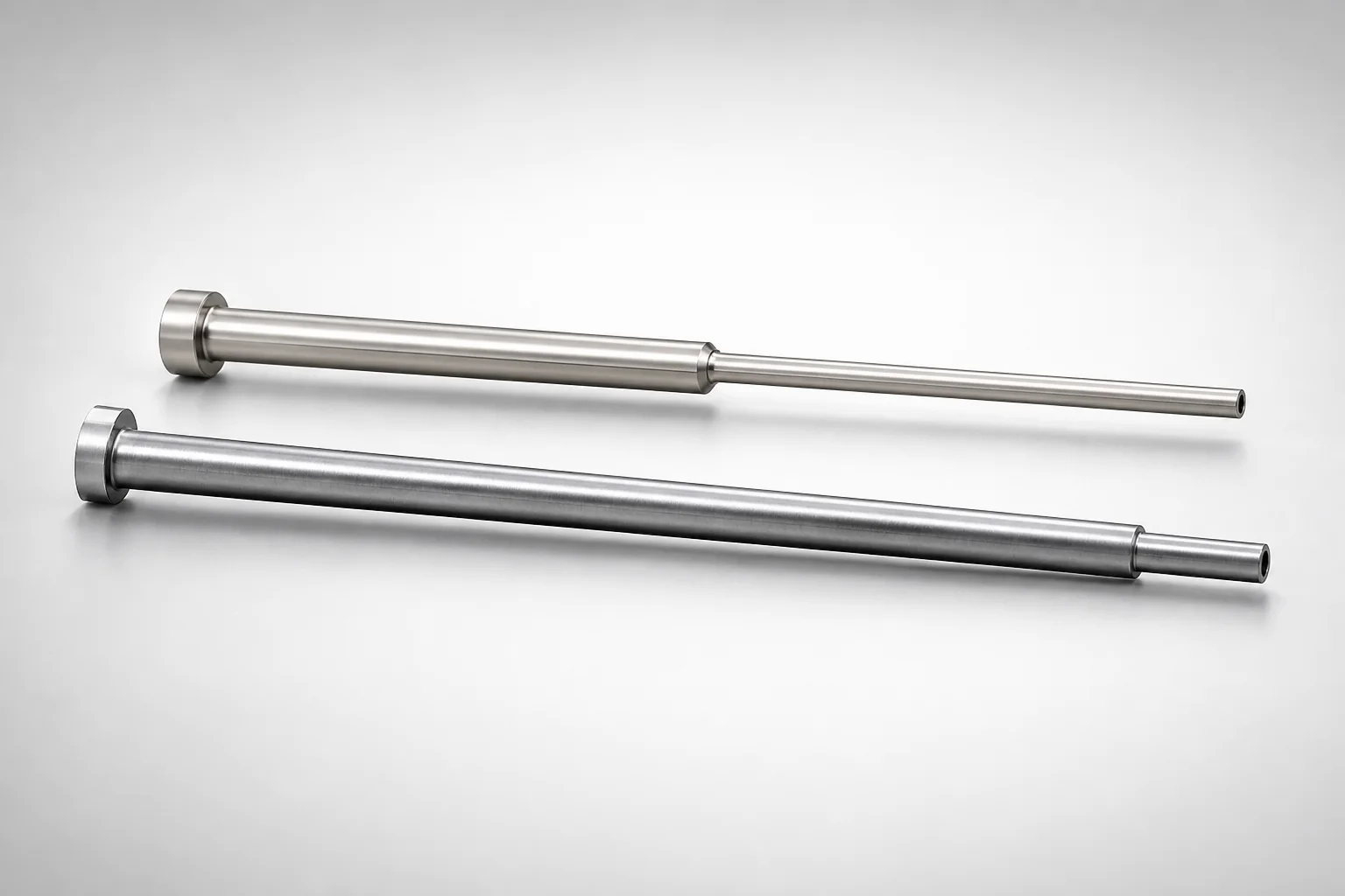
JIS Standard SKH51 Steel Precision Stepped Ejector Sleeves (ESVF)
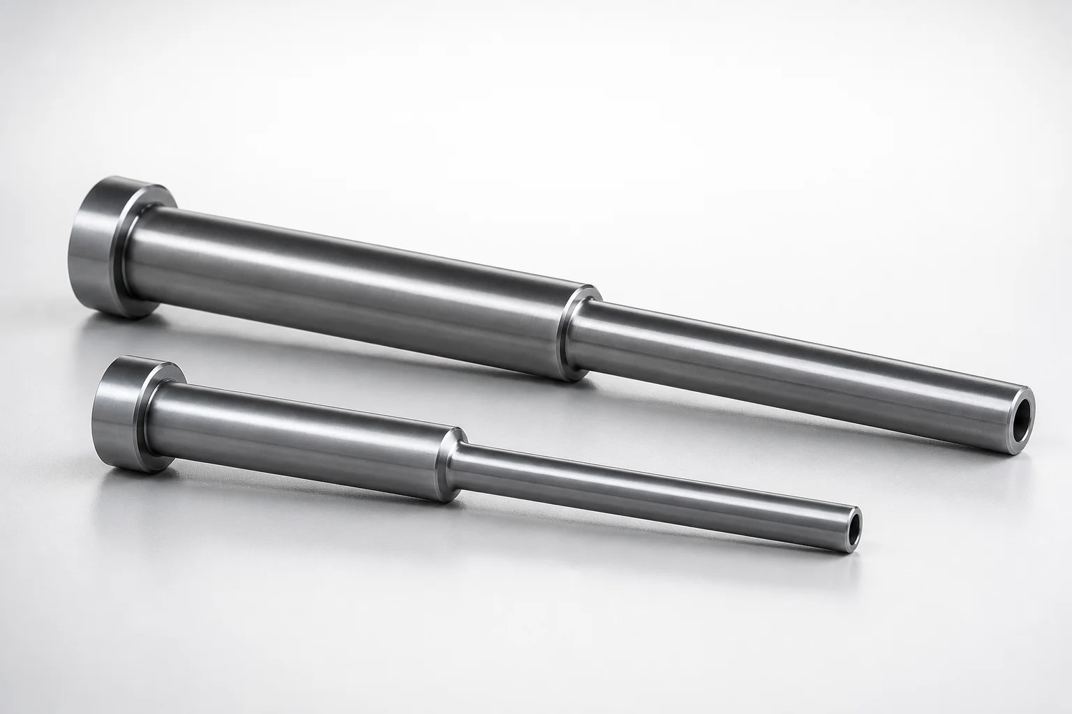
JIS Standard SKD61 Steel Stepped Ejector Sleeves
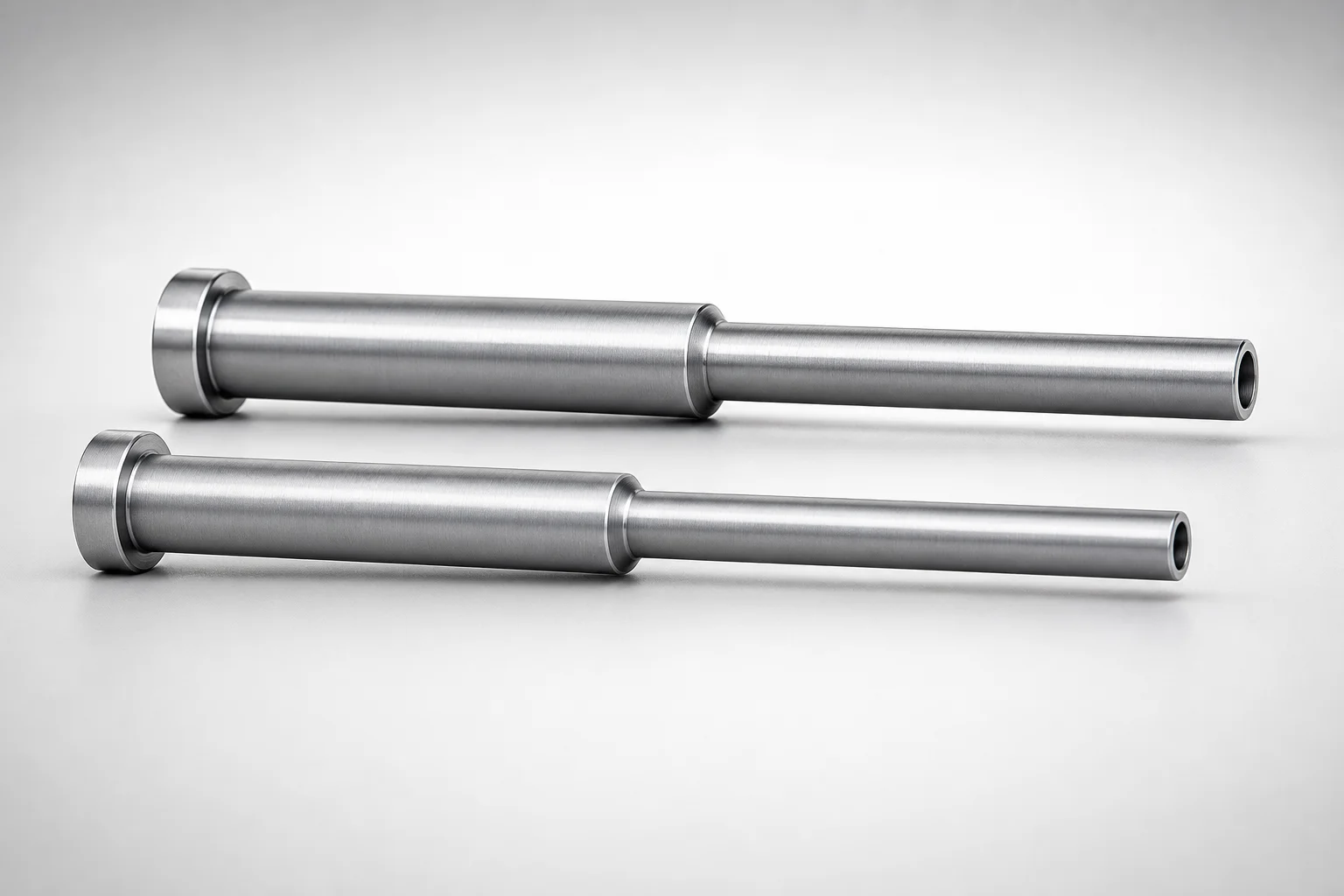
JIS Standard SKD61 Steel Stepped Ejector Sleeves
ESNF Type SKD61 Hardened Steel Stepped Ejector Sleeves
Japanese Standard SKD61 Steel Stepped Ejector Sleeves
JIS Standard SKD61 Steel Stepped Ejector Sleeves
Need Custom Specifications?
Our engineering team can help with custom configurations, material selection, and volume pricing.