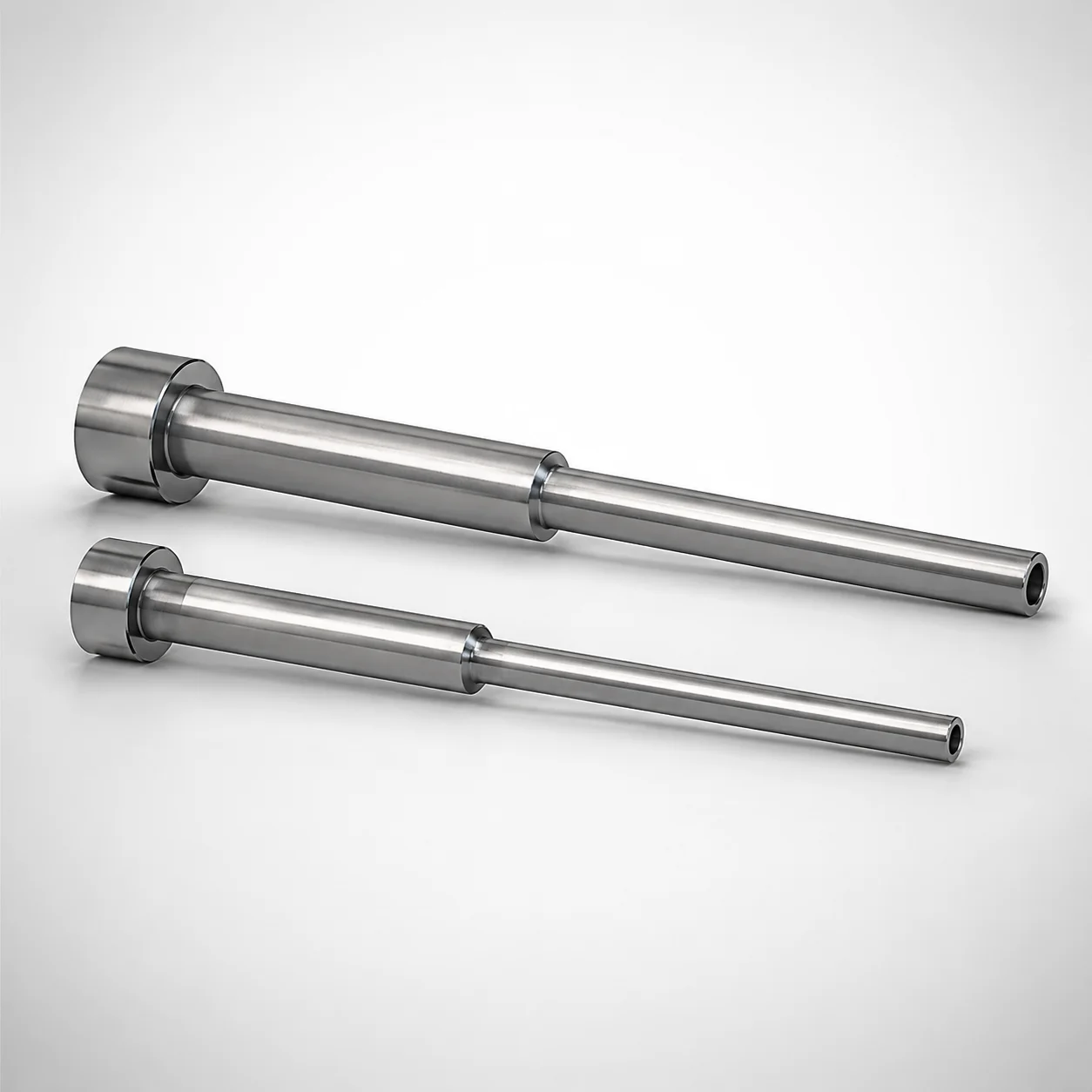
JIS Standard SKD61 Equivalent Stepped Ejector Sleeves
JIS Standard stepped ejector sleeves (SKD61 equivalent) are built as a single-sleeve component with nitrided surface treatment to support stable fit and long service in injection molds. The stepped geometry helps guide ejector movement for consistent part release.
- Stepped sleeve construction for reliable alignment and ejection guidance
- Nitrided surface treatment enhances wear resistance under repetitive cycles
- Supported tolerance control with shaft diameter variation for stable assembly
- Designed for ESJFC stepped ejector sleeve applications
Specifications
15 configurations available
| Head Thickness | D (Shaft Diameter) (mm) | P (Tip Diameter) (mm) | V (Hole Diameter) (mm) | L (L dimension) (mm) | Dimension N (mm) | S (V hole diameter length) (mm) | type |
|---|---|---|---|---|---|---|---|
| 6mm(JIS) | 5 | 3.5 ~ 4.8 | 2 ~ 3.3 | 50 ~ 400 | 17 ~ 400 | 1 ~ 150 | - |
| 6mm(JIS) | 6 | 3.5 ~ 5.8 | 2.5 ~ 4.1 | 50 ~ 600 | 17 ~ 600 | 1 ~ 150 | - |
| 6mm(JIS) | 7 | 3.5 ~ 6.8 | 2.5 ~ 5.1 | 50 ~ 600 | 17 ~ 600 | 1 ~ 150 | - |
| 8mm(JIS) | 8 | 3.5 ~ 7.8 | 2.5 ~ 6.1 | 50 ~ 600 | 17 ~ 600 | 1 ~ 150 | - |
| 8mm(JIS) | 9 | 4.5 ~ 8.8 | 2.5 ~ 6.8 | 50 ~ 800 | 17 ~ 800 | 1 ~ 150 | - |
| 8mm(JIS) | 10 | 4.5 ~ 9.8 | 2.5 ~ 7.8 | 50 ~ 800 | 17 ~ 800 | 1 ~ 150 | - |
| 8mm(JIS) | 11 | 4.5 ~ 10.8 | 2.5 ~ 8.3 | 50 ~ 800 | 17 ~ 800 | 1 ~ 150 | - |
| 8mm(JIS) | 12 | 4.5 ~ 11.8 | 2.5 ~ 9.3 | 50 ~ 800 | 17 ~ 800 | 1 ~ 150 | - |
| 8mm(JIS) | 13 | 6 ~ 12.8 | 2.5 ~ 10.3 | 50 ~ 800 | 17 ~ 800 | 1 ~ 150 | - |
| 8mm(JIS) | 14 | 7 ~ 13.8 | 2.5 ~ 11.3 | 50 ~ 800 | 17 ~ 800 | 1 ~ 150 | - |
| 8mm(JIS) | 15 | 7 ~ 14.8 | 2.5 ~ 12.3 | 50 ~ 900 | 17 ~ 900 | 1 ~ 150 | - |
| 8mm(JIS) | 18 | 8 ~ 15.8 | 2.5 ~ 12.8 | 50 ~ 900 | 17 ~ 900 | 1 ~ 150 | - |
| 8mm(JIS) | 17 | 8 ~ 16.8 | 2.5 ~ 13.8 | 50 ~ 900 | 17 ~ 900 | 1 ~ 150 | - |
| 8mm(JIS) | 18 | 9 ~ 17.8 | 2.5 ~ 14.8 | 50 ~ 900 | 17 ~ 900 | 1 ~ 150 | - |
| 8mm(JIS) | 20 | 10 ~ 19.8 | 2.5 ~ 16.8 | 50 ~ 900 | 17 ~ 900 | 1 ~ 150 | - |
Product Guide
Application Scenarios+
These nitrided stepped ejector sleeves are used in injection mold tooling where consistent ejector alignment is critical. The stepped profile acts as a mechanical guide, helping stabilize ejector movement during high-cycle part ejection, especially in molds that see frequent start-stop production.
- Automotive and appliance housings: In ejector systems for medium-to-large plastic parts, the sleeve supports repeatable ejection guidance, reducing stick-slip behavior when dimensional loads cycle thousands of times.
- General electronics enclosure molds: Single-sleeve stepped geometry helps maintain coaxiality with the ejector pin set, supporting stable fit across the available shaft diameter range (D: 5–20 mm).
- ESJFC stepped ejector sleeve assemblies: The product is designed specifically for ESJFC stepped ejector sleeve applications, making it suitable when the mold designer requires a controlled wear surface for long service life.
The nitrided variant is well-suited for abrasive wear at the sleeve interface while preserving dimensional control needed for reliable ejection.
Material & Process Details+
This component is specified as a JIS Standard SKD61 equivalent stepped ejector sleeve. SKD61 is widely treated as comparable to AISI H13-grade tooling steel in terms of hot-work die steel performance, offering good toughness for cyclic molding loads.
- Surface condition: The sleeve is nitrided, providing a hard, wear-resistant surface layer to improve resistance to repetitive sliding contact.
- Hardness and trade-off: The nitriding hardens the near-surface region for wear control, while the SKD61-equivalent steel body maintains toughness to resist chipping and cracking under cyclic ejection forces. Exact HRC values are not provided in the supplied specifications.
- Wear vs. toughness: Nitriding primarily improves wear performance; deeper toughness is controlled by the base steel condition inherent to SKD61-equivalent tooling materials.
Compared with un-nitrided variants, nitriding improves controlled wear at the sleeve-to-ejector interface, which is beneficial for stable fit over long runs.
Sizing & Selection Guide+
Select the stepped ejector sleeve by matching the mold’s ejector guide requirements to the specified dimensional set. Start with D (shaft diameter) in the range 5–20 mm—this should correspond to the ejector shaft diameter it will guide.
- Tip and guiding geometry: Choose P (tip diameter) within 3.5–10 mm to match the mating stepped feature of the ejector/pin assembly.
- Hole sizing: Set V (hole diameter) to 2–2.5 mm, and use the fixed S (V hole diameter length) of 1–150 mm to match required through-hole engagement length.
- Length matching: Select L from the available ranges (e.g., 50–400, 50–600, 50–800, 50–900) consistent with your mold stack-up.
- Stepped section height (N): Choose Dimension N from the corresponding ranges (e.g., 17–400, 17–600, 17–800, 17–900) to achieve proper guidance overlap.
Account for assembly tolerances in the mold design: nitrided surfaces improve wear resistance, but dimensional fit still depends on the overall ejector and sleeve tolerance scheme used for the ESJFC stepped ejector sleeve assembly.
Frequently Asked Questions
Does this stepped ejector sleeve use an SKD61 equivalent steel grade, and is it nitrided?+
What shaft diameter (D) range is available for selecting the sleeve for my ejector system?+
How do I choose L and N when my mold requires longer guide engagement?+
What are the available tip diameter (P) and hole diameter (V) specifications for this sleeve?+
Is this sleeve intended for ESJFC stepped ejector sleeve applications?+
Related Products
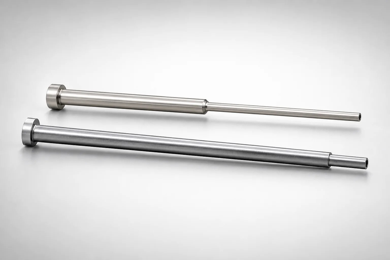
JIS Standard SKH51 Steel Precision Stepped Ejector Sleeves (ESVF)
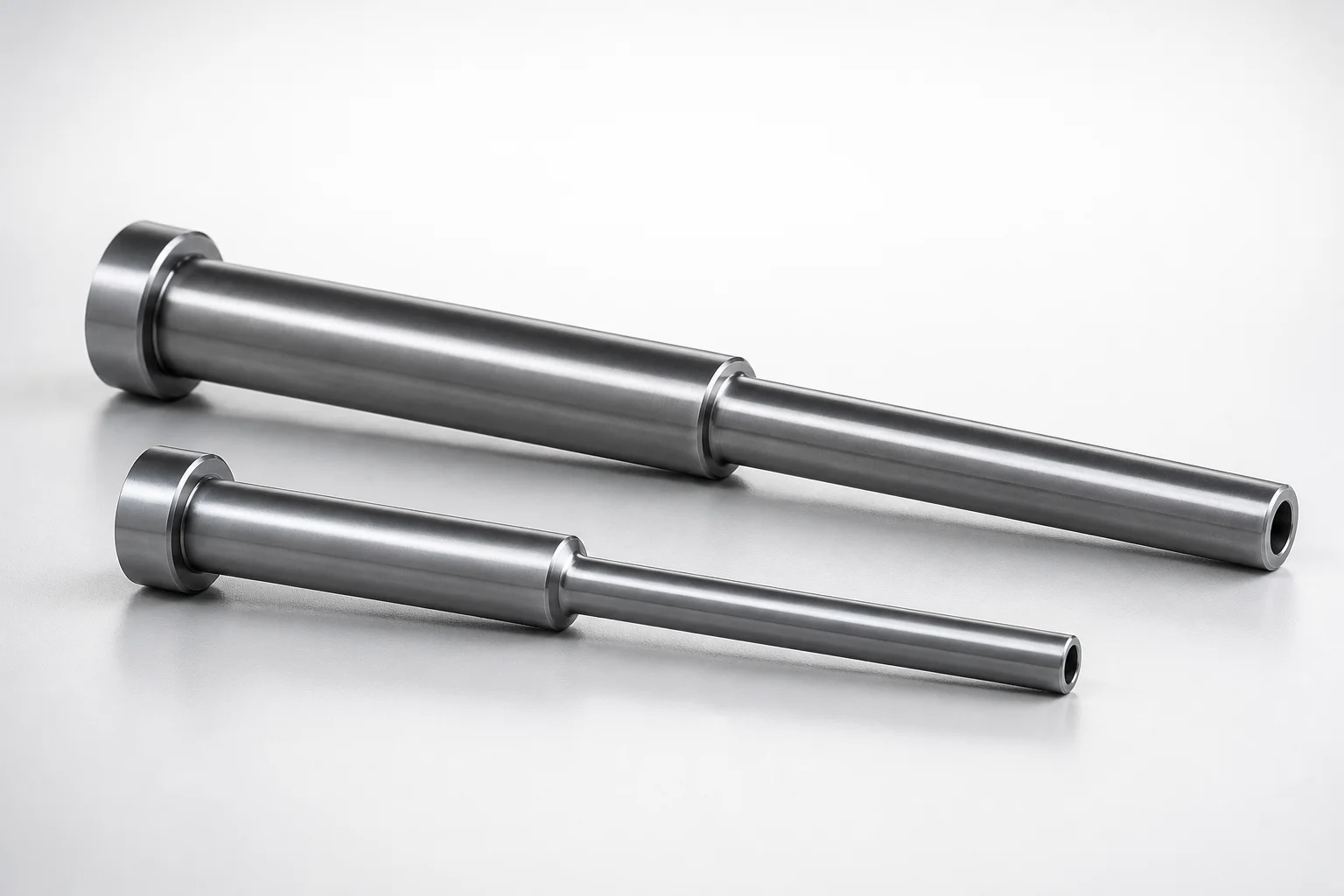
JIS Standard SKD61 Steel Stepped Ejector Sleeves
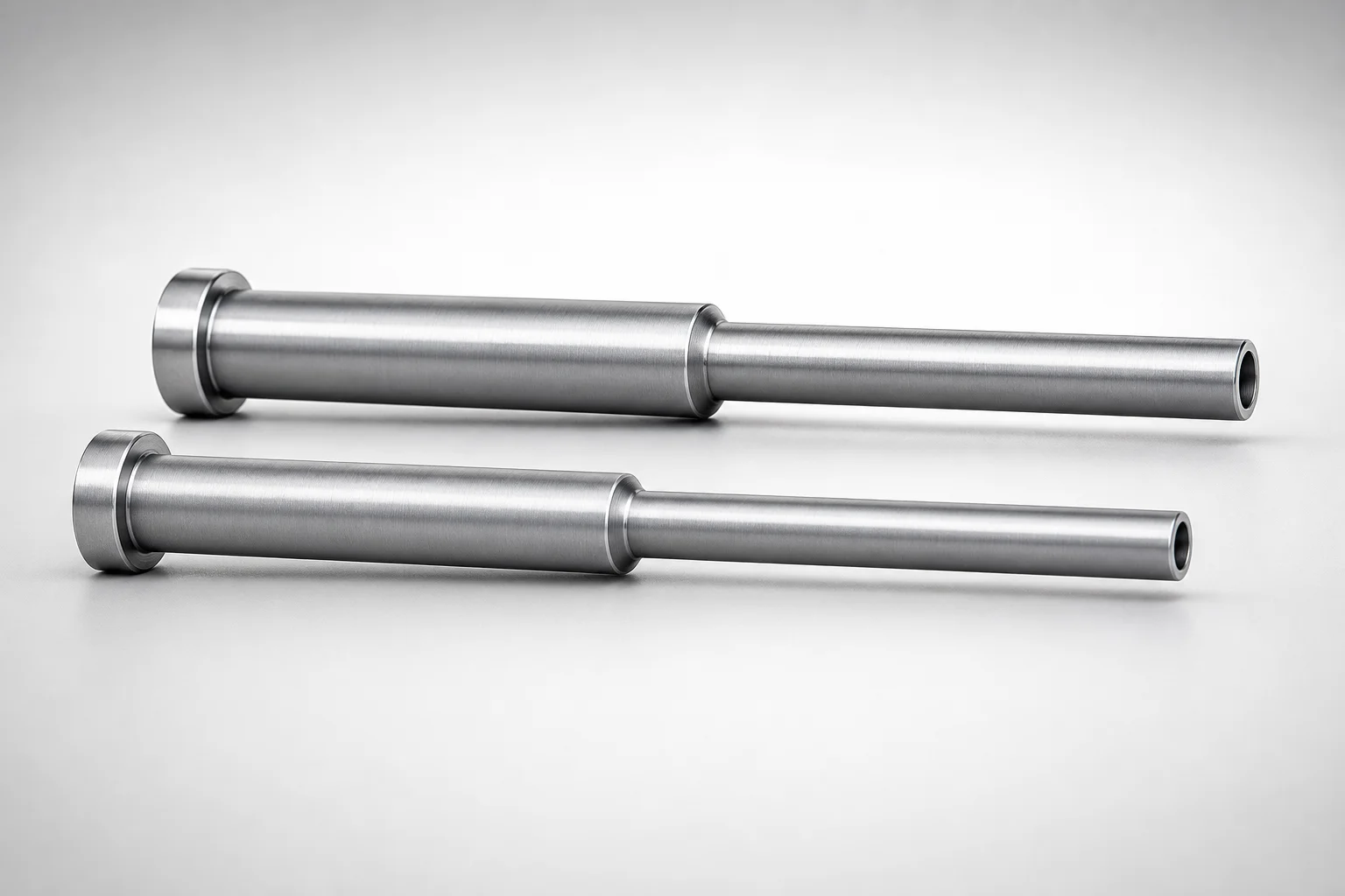
JIS Standard SKD61 Steel Stepped Ejector Sleeves
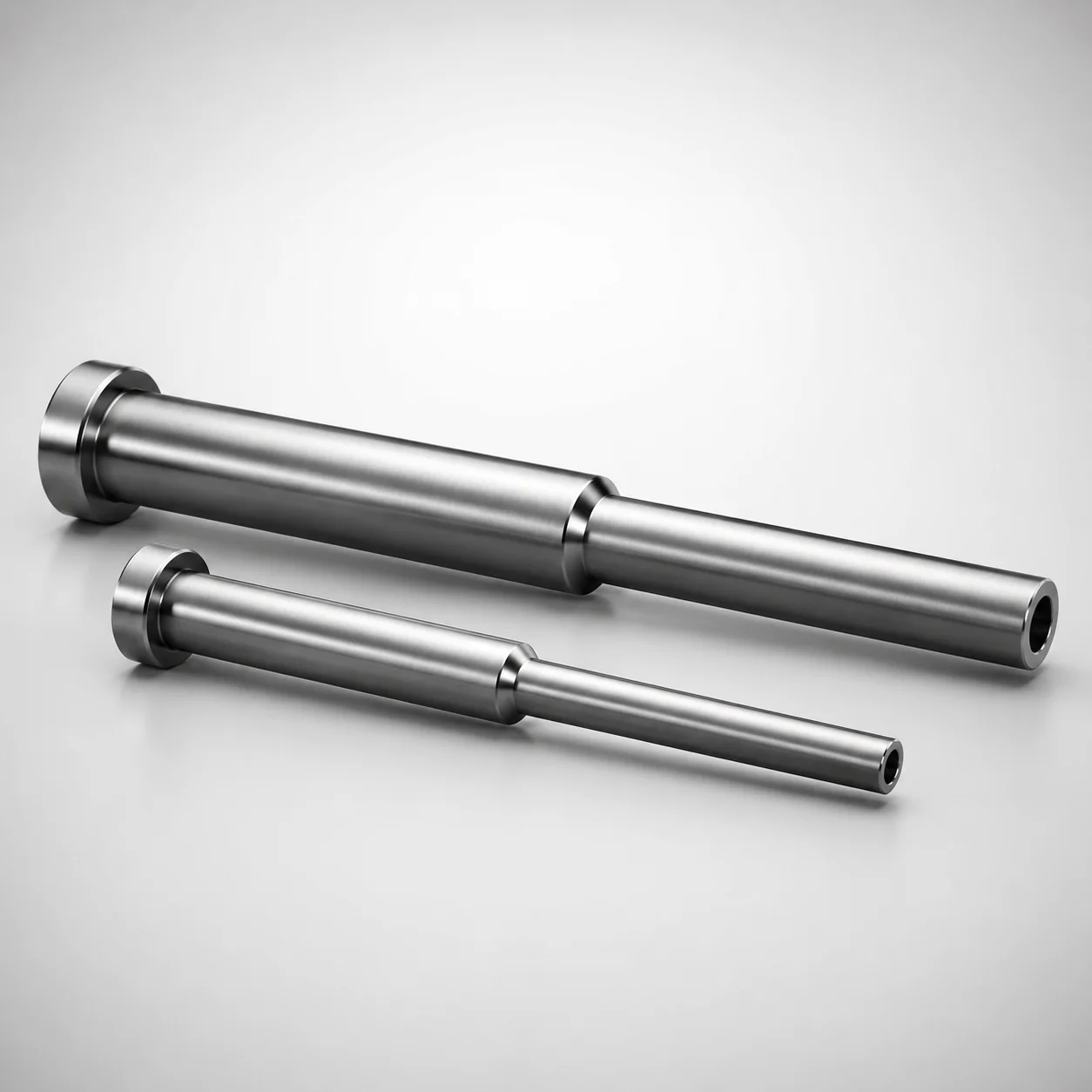
ESNF Type SKD61 Hardened Steel Stepped Ejector Sleeves
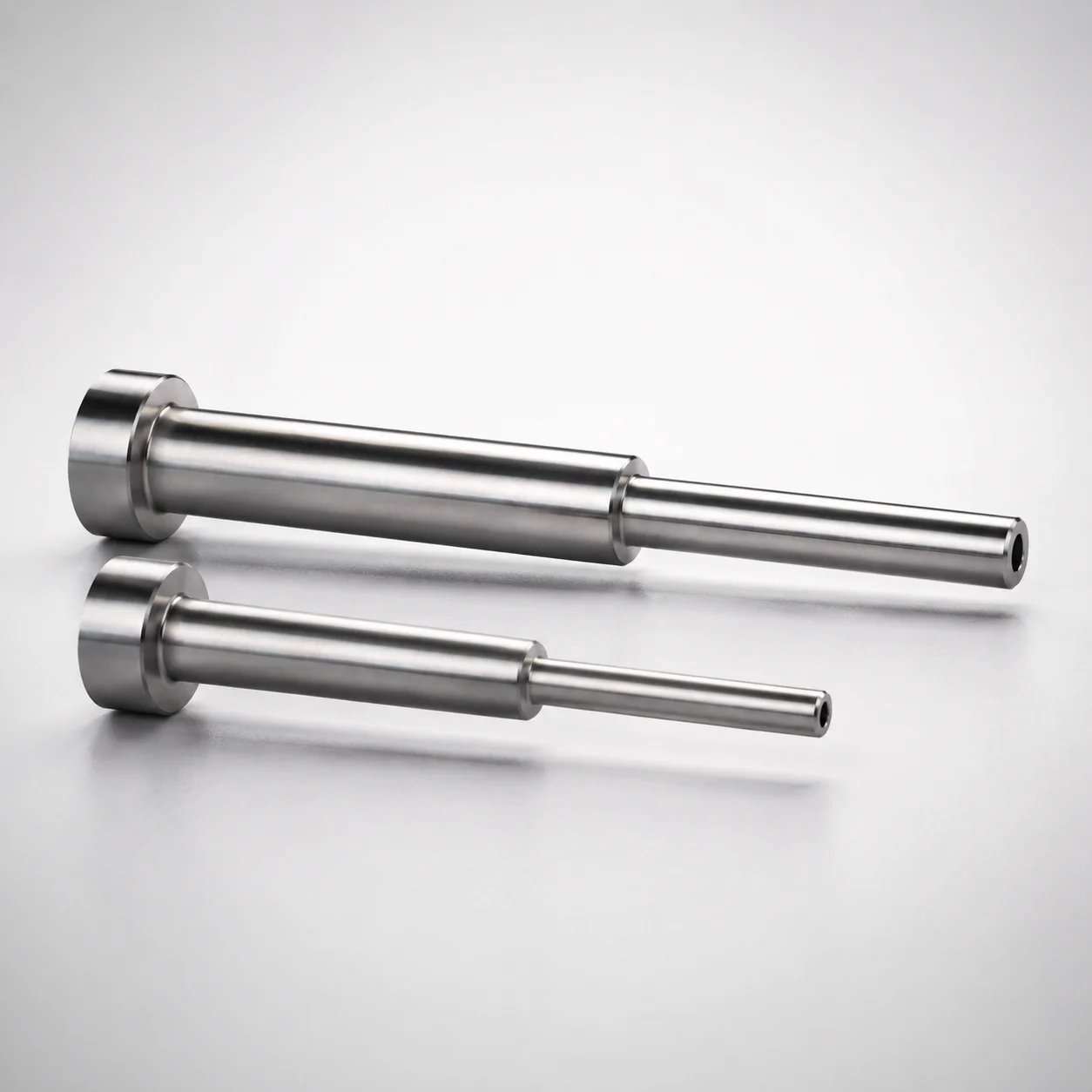
Japanese Standard SKD61 Steel Stepped Ejector Sleeves
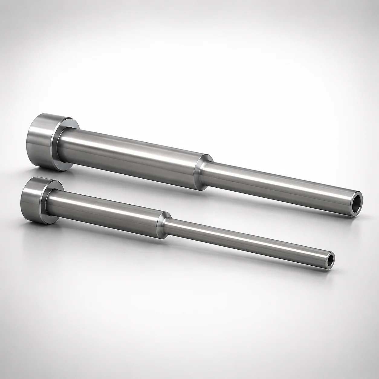
JIS Standard SKD61 Steel Stepped Ejector Sleeves
Need Custom Specifications?
Our engineering team can help with custom configurations, material selection, and volume pricing.