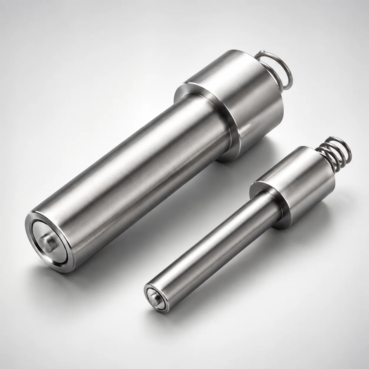
MSTV Gas Vent Units - Valves and Springs Cavity Inserts
MSTV Gas Vent Units - Valves and Springs cavity inserts are engineered to manage gas release in injection molding by maintaining efficient venting performance. They help reduce gas buildup, protect sensitive systems, and support stable production quality.
- Gas vent unit insert design supports controlled venting during molding cycles
- Durable valve and spring construction helps prevent harmful gas accumulation
- Built for reliable cavity insert performance to safeguard mold systems
- Type MSTV for use in tooling requiring consistent gas management
Specifications
3 configurations available
| D (Outer diameter) (mm) | L (L dimension) (mm) | F (Tip protrusion) (mm) | type |
|---|---|---|---|
| 2 | 20 | - | - |
| 3 | 20 | 0.3 | - |
| 6 | 25 | 0.5 | - |
Product Guide
Application Scenarios+
In injection mold tooling, this type of gas vent unit insert is used in cavity or core areas where trapped air and decomposition gases can accumulate. During the filling and packing phases, the valve-and-spring mechanism provides controlled venting that helps reduce gas pressure buildup and limits defects such as burn marks or void formation.
- Electronics and appliance housings: Install near dense feature transitions to vent air pockets efficiently while protecting adjacent tooling surfaces from gas-related degradation.
- Automotive interior components: Use in thin-wall or vent-critical cavities to improve repeatable part appearance and reduce cycle-to-cycle variability.
- Packaging and consumer goods molds: Appropriate for short-to-medium runs where stable venting protects the mold system and reduces rework caused by gas-related surface issues.
The insert variant with a valve and spring style supports consistent gas management under molding conditions, improving overall venting reliability and tooling safety.
Material & Process Details+
The provided specifications define the insert’s functional geometry (D, L, and F) but do not specify the steel grade or heat-treatment state. Therefore, this page should treat the material/process selection as application-dependent and align it with your mold shop’s standard practices for cavity inserts and gas vent components.
- Material properties to target: sufficient surface hardness for wear resistance at the venting tip, and adequate toughness to resist chipping from repeated valve actuation.
- Heat treatment (typical for vent inserts): many tooling steels are supplied quenched & tempered or nitrided to balance wear resistance with toughness; select the route based on your gas environment and cycle frequency.
- Trade-offs: higher hardness improves wear resistance but may reduce toughness—coordinate the hardness level with expected vent duty and safety factor.
Sizing & Selection Guide+
Select the insert geometry by matching the intended vent location, available pocket space, and the required vent tip reach into the cavity flow path. This series provides multiple fixed sizes: D (outer diameter) = 2, 3, or 6 mm, L (L dimension) = 20 or 25 mm, and F (tip protrusion) = 0.3 or 0.5 mm.
- Choose D: Use the 2/3/6 mm outer diameter that fits your designed cavity insert pocket diameter and supports stable seating.
- Choose L: Set L = 20 or 25 mm to ensure the insert body fully engages your pocket depth without bottoming out.
- Choose F: Use F = 0.3 or 0.5 mm to control the vent tip protrusion into the cavity—higher F generally increases venting influence, but must be validated against clearance and flash risk.
Confirm compatibility with your locating/retention method and apply your standard mold-shop tolerances for cavity insert fit (seat clearance and concentricity) to maintain repeatable vent performance.
Frequently Asked Questions
Which size should I select for gas vent units—how do D, L, and F affect vent performance?+
In this series, D (outer diameter) is the fit-related dimension (2, 3, or 6 mm), while L (20 or 25 mm) controls pocket depth engagement. F (tip protrusion, 0.3 or 0.5 mm) primarily determines how far the vent tip influences the cavity flow path during molding. If flash risk or interference is a concern, start with the smaller F and validate venting stability.
How do I ensure the insert will seat properly in my cavity insert pocket for MSTV vent units?+
Use D to match the designed pocket diameter and L to match pocket depth. With available L values of 20 or 25 mm, confirm that the insert body can fully engage without bottoming. Apply your standard tolerances for cavity insert seating and concentricity so the vent unit remains stable through repeated molding cycles.
What tip protrusion (F = 0.3 vs 0.5 mm) is recommended for thin-wall cavities with burn risk?+
Tip protrusion (F) influences venting influence at the cavity surface. For thin-wall cavities where clearance and flash sensitivity are higher, engineers often start with F = 0.3 mm to reduce risk of interference while still enabling controlled venting. Use F = 0.5 mm when stronger vent effect is required, and validate with first-article mold trials.
Are these MSTV gas vent inserts suitable for high-cycle production, and what material/heat-treatment should I specify?+
The provided data lists only D, L, and F and does not specify a steel grade or heat treatment. For high-cycle use, specify a vent-insert material system that delivers strong surface wear resistance at the valve tip and adequate toughness for repeated actuation. Coordinate hardness, and consider quenched & tempered or nitrided approaches based on your gas conditions and cycle rate.
What tooling locations typically benefit most from MSTV valves and springs cavity inserts?+
MSTV-style valve-and-spring venting is most beneficial where trapped air or gases tend to accumulate, such as near dense transitions or areas prone to burn marks. It is commonly used in cavities requiring consistent vent management to protect sensitive molding systems and improve repeatable surface quality. When planning placement, align the vent tip using the selected F value and verify clearances to avoid flash or interference.
Related Products
Need Custom Specifications?
Our engineering team can help with custom configurations, material selection, and volume pricing.