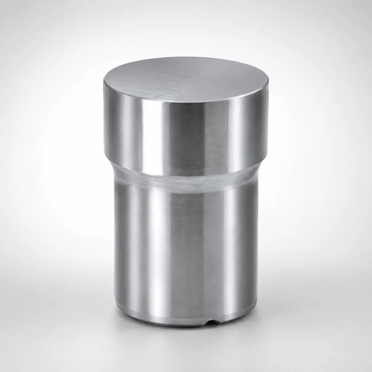
BGVS Gas Release Cavity Inserts Round Shape Bevels on Circumference
BGVS gas release cavity inserts (round shape with circumferential bevels) are designed to improve venting during molding, helping eliminate trapped air and stabilize cavity pressure. This insert configuration supports consistent surface finish and reduces air-related defects.
- Gas release design supports efficient venting to reduce air traps
- Round insert geometry with circumferential bevels promotes airflow clearance
- Durable cavity insert construction helps maintain mold integrity in production
- Suitable for precision molding applications requiring controlled exhaust performance
Specifications
6 configurations available
| D (Outer diameter) (mm) | S (Groove width) (mm) | type |
|---|---|---|
| 6 | 0.03 | - |
| 6 | 0.05 | - |
| 8 | 0.03 | - |
| 8 | 0.05 | - |
| 10 | 0.03 | - |
| 10 | 0.05 | - |
Product Guide
Application Scenarios+
BGVS gas release cavity inserts are used in injection mold tooling where trapped air can cause burn marks, short shots, or voids. The round insert body with circumferential bevels is placed in the cavity surface to create a controlled vent path, improving purge efficiency and helping stabilize cavity pressure during filling.
- Consumer goods and housing components: Ideal for thin-wall or high-flow parts where localized air entrapment leads to surface blemishes; the bevel geometry supports airflow clearance around the insert features.
- Precision molded devices (general): Used in molds that demand consistent surface finish; the insert helps reduce air-related defects by improving exhaust performance without relying on large vent depths.
- High-cadence production: Suitable when repeatability matters; the insert configuration is intended to maintain reliable venting behavior across production cycles.
Material & Process Details+
The provided specifications describe the BGVS gas release insert geometry (outer diameter and groove width), but no steel grade, heat-treatment condition, or hardness values are included in the input data. Therefore, material property claims such as HRC hardness, wear resistance, toughness trade-offs, and heat treatment state (e.g., nitriding or quench & temper) cannot be stated from the supplied information.
For cavity inserts in gas-vent applications, engineers typically select tool steels based on expected molding abrasiveness and thermal cycling. If you share the steel grade or applicable MISUMI material option for series code 110200054170, the exact correspondence (e.g., SKD61/H13) and the correct heat-treatment and hardness targets can be documented.
Sizing & Selection Guide+
Select the insert outer diameter (D) and groove width (S) to match the vent feature requirements on the mold cavity/core. For this series, available dimensions are D = 6, 8, or 10 mm and S = 0.03 or 0.05 mm.
- Match to cavity layout: Choose D based on the available recess/spot area on the cavity surface and the proximity to functional surfaces that must maintain cosmetic or dimensional integrity.
- Set vent aggressiveness via S: Use the smaller groove width (S = 0.03 mm) when you want finer vent restriction; use S = 0.05 mm when slightly higher exhaust conductance is needed to purge trapped air.
- Fit and tolerance: Ensure the insert seating geometry provides stable alignment and consistent contact with the cavity surface to avoid vent performance drift. Use your mold manufacturer’s standard insert pocket tolerances to control installed position.
Dimensions listed above are configurable by variant; geometry selection should be finalized before machining the insert pocket for the chosen cavity location.
Frequently Asked Questions
Which vent performance parameter should I choose: outer diameter D or groove width S?+
In this BGVS configuration, D (6, 8, 10 mm) primarily governs how the insert feature fits into the cavity surface area. S (0.03 or 0.05 mm) is the groove width that directly affects vent restriction and exhaust conductance. For tuning air purge, engineers typically vary S while keeping D consistent with the available pocket geometry.
How do I select D (6/8/10 mm) for a specific cavity location without compromising surface finish?+
Choose D based on the available recess size on the cavity/core and the allowable area around cosmetic features. Larger D provides a broader insert footprint, but it also increases the area of the vent feature on the cavity surface. Use the smallest D that still provides the required seating and alignment for stable venting behavior.
What is the practical difference between S = 0.03 mm and S = 0.05 mm?+
S defines the groove width for the gas release vent feature. With S = 0.03 mm, the vent path is more restricted, which can help limit over-venting while still purging trapped air. With S = 0.05 mm, vent conductance is higher, which can improve exhaust effectiveness in areas prone to air entrapment.
Are there material or heat-treatment differences across this series code 110200054170?+
The supplied product data does not include a steel grade, hardness (HRC), or heat-treatment state for series code 110200054170. To confirm material/heat-treatment differences between variants, you’ll need the specific material option details tied to the SKU/series selection. Share the intended MISUMI material/grade and we can map the exact heat treatment and expected wear/toughness characteristics.
What pocket tolerance should I plan for when installing BGVS gas release inserts?+
The input data lists D = 6/8/10 mm and S = 0.03/0.05 mm but does not provide explicit tolerance values. In practice, you should control insert pocket dimensions to maintain consistent installed position and vent geometry. Use your internal mold-shop tolerance standards for insert pockets and confirm with a feasibility check against the cavity machining process.
Related Products
Need Custom Specifications?
Our engineering team can help with custom configurations, material selection, and volume pricing.