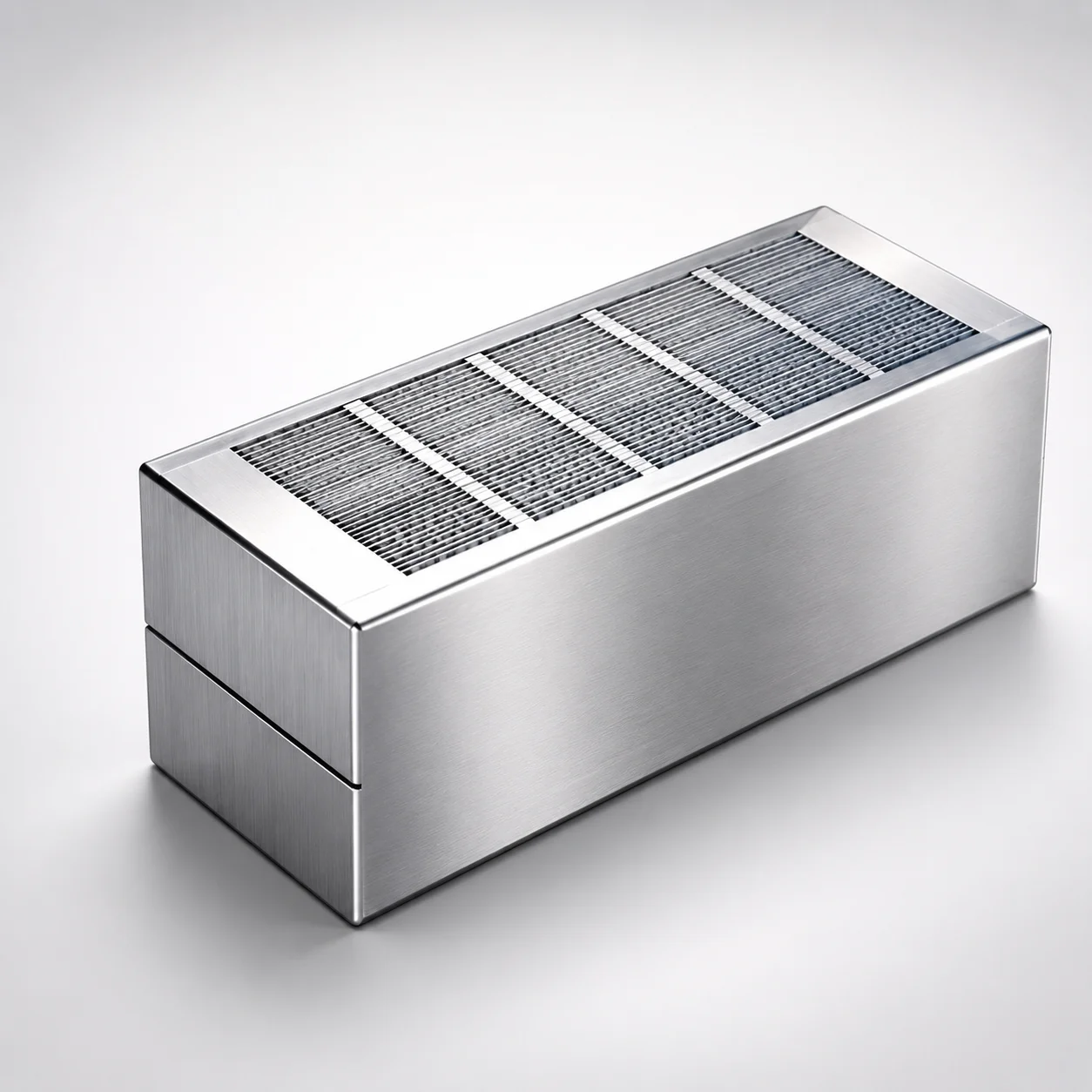
Degassing Slit Vent Cavity Insert Blocks
Degassing slit vent cavity insert blocks are precision mold cavity inserts that create a controlled vent path for gas release and residual air removal. A diffusion-bonded fine slit structure enables stable degassing once installed in the mold.
- Fine slit vent design supports consistent gas release and exhaust
- Diffusion bonding forms a micro slit structure for reliable degassing
- Optimized slit-width configurations help match cavity venting requirements
- Used in mold cavity insert applications requiring improved air evacuation
Specifications
6 configurations available
| A (Length) (mm) | KD (Square Machining) Additional Processing | type |
|---|---|---|
| 12 | No | - |
| 12 | Yes | - |
| 24 | No | - |
| 24 | Yes | - |
| 24 | No | - |
| 24 | Yes | - |
Product Guide
Application Scenarios+
Degassing slit vent cavity insert blocks are used in injection mold tooling wherever trapped air and process gases must be removed to prevent burn marks, short shots, and surface defects. In automotive connector and housing molds, the insert is installed in an appropriate cavity insert location to provide a controlled vent path; the diffusion-bonded fine slit structure helps maintain stable degassing during repeated cycles.
For consumer electronics housings and thin-wall parts, the slit vent design supports consistent exhaust of residual air near high-filling-rate regions, improving appearance and reducing incomplete fill risks. The slit-width configuration capability (matched to venting requirements during selection) makes it suitable when venting needs to be tuned without enlarging conventional vent channels.
In general cavity insert assemblies, choose the variant that aligns with your cavity layout and the available machining options, ensuring secure installation and reliable gas release over the full production window.
Material & Process Details+
The provided specification data for this product focuses on the venting architecture and dimensional options rather than disclosing a specific steel grade, HRC hardness, or heat-treatment route. As a result, hardness, wear resistance, and toughness trade-offs cannot be stated from the available inputs.
What is specified is the vent mechanism: a diffusion-bonded fine slit structure that forms a stable micro-slit diffusion path once installed. This structure is designed to enhance venting efficiency by supporting consistent gas release while managing residual air evacuation.
- Manufacturing/process emphasis: diffusion bonding to build the fine slit microstructure.
- Heat treatment: not specified in the provided parameters; confirm from datasheets or order documentation if a specific hardened condition is required.
If you need a particular wear or thermal performance target, share your cavity pressure/temperature range and any expected abrasive compounds so Axiom Molds can recommend a matching material condition.
Sizing & Selection Guide+
Select the correct vent insert dimensions by matching the available Length A (mm) and the required installation geometry in your cavity/core. This series provides A = 12 mm or 24 mm, so choose the length that spans the intended vent zone in the cavity insert area.
Next, review the KD (Square Machining) additional processing option. With KD additional processing: No or Yes, the “Yes” configuration is intended for square machining needs in your assembly, while “No” is suitable when your tooling can accommodate the standard form factor.
- Measure the cavity insert pocket and align the insert length to cover the gas-escape region without interfering with adjacent cavity surfaces.
- Confirm fit and contact conditions (clearances, seating depth, and any locating features) in your CAD so the vent pathway remains open after assembly.
- If your mold design uses multiple inserts, ensure vented regions align with flow front locations to avoid air entrapment.
Frequently Asked Questions
How does the diffusion-bonded slit structure improve degassing compared with conventional straight vents?+
This design uses a diffusion-bonded fine slit microstructure to provide a controlled vent path for gas release and residual air removal. The diffusion-bonding supports stable degassing once installed, helping maintain consistent exhaust behavior across production cycles.
Which length option (A = 12 mm or 24 mm) should I choose for my cavity vent zone?+
Choose A = 12 mm when your venting requirement is confined to a shorter region in the cavity insert pocket, such as localized high-air-trap areas. Select A = 24 mm when you need the vent pathway to cover a longer part of the cavity insert, improving evacuation over a broader area.
What does the KD square machining option mean, and when should I select KD = Yes?+
The specification lists KD additional processing as No or Yes. Select KD = Yes if your cavity insert mounting requires the square machining feature; choose KD = No when your pocket and assembly geometry are compatible with the standard configuration.
Can slit vent cavity insert blocks be used as part of a cavity insert stack or only as a dedicated insert?+
They are intended for mold cavity insert applications that require improved air evacuation. In practical tooling, they can be integrated within cavity insert layouts as long as the vent pathway remains unobstructed and the insert seats correctly in the pocket.
Is slit-width selection available in this series, and how should I match it to cavity requirements?+
The product description notes that optimized slit-width configurations help match cavity venting requirements. When selecting a block, align the venting configuration to your cavity geometry and expected gas generation (e.g., thin-wall filling and areas prone to residual air).
Related Products
Need Custom Specifications?
Our engineering team can help with custom configurations, material selection, and volume pricing.