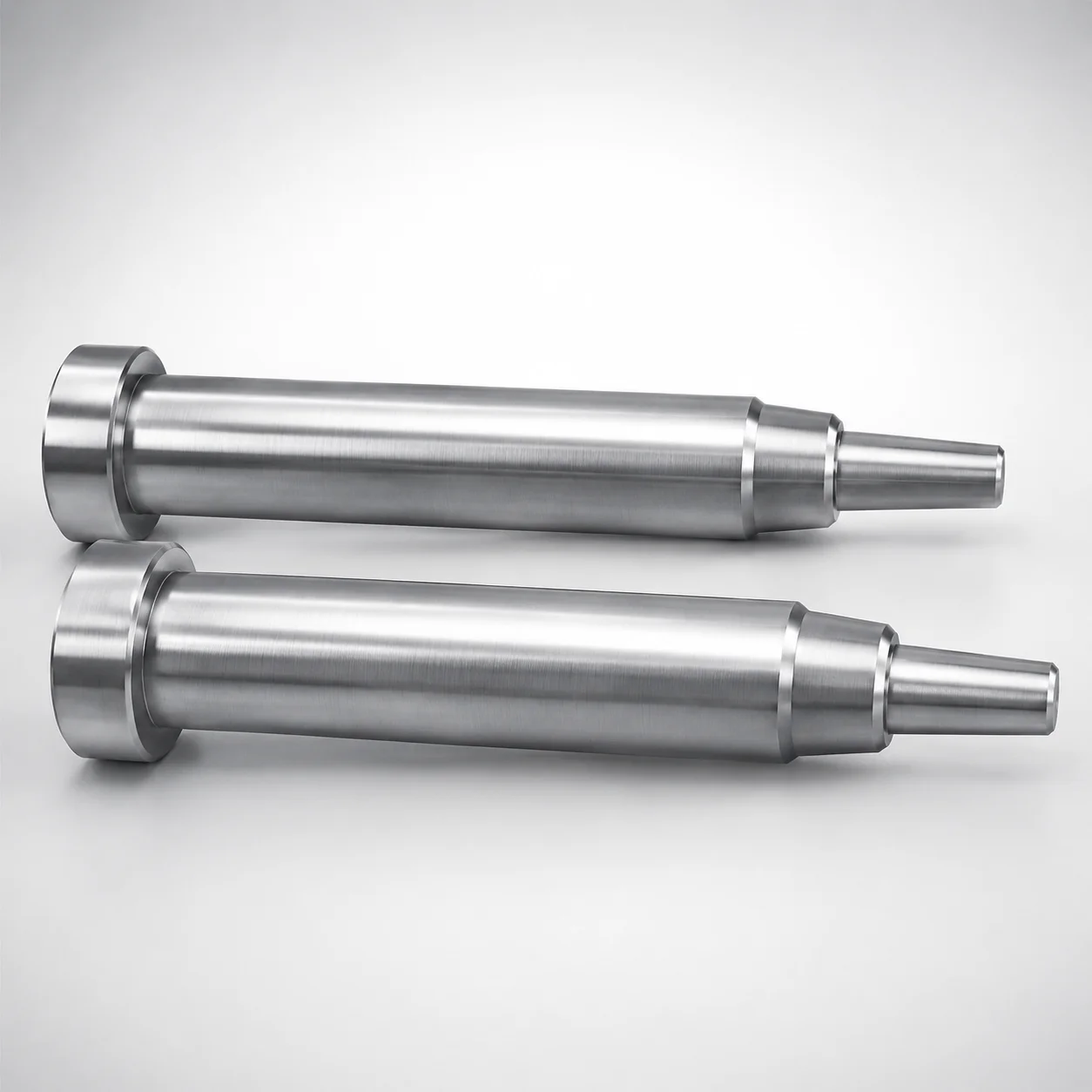
Two-Step Core Pins Head T=4 mm
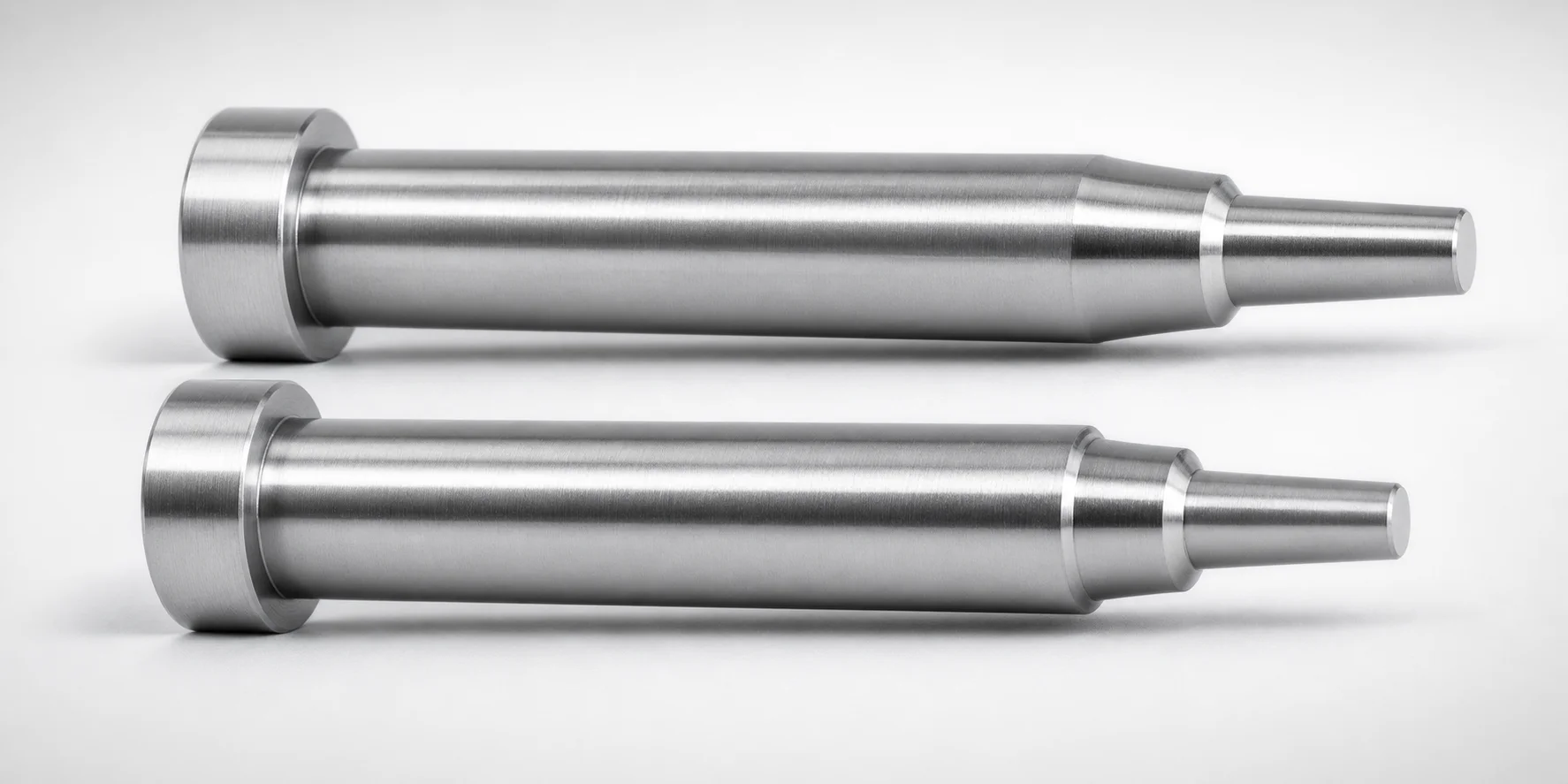
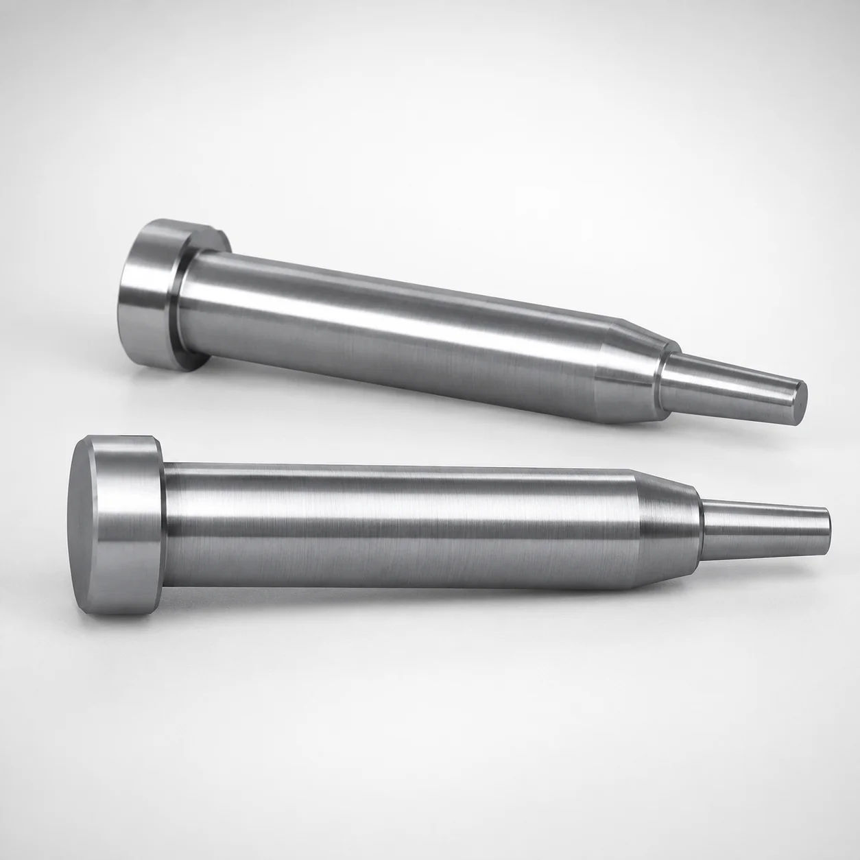
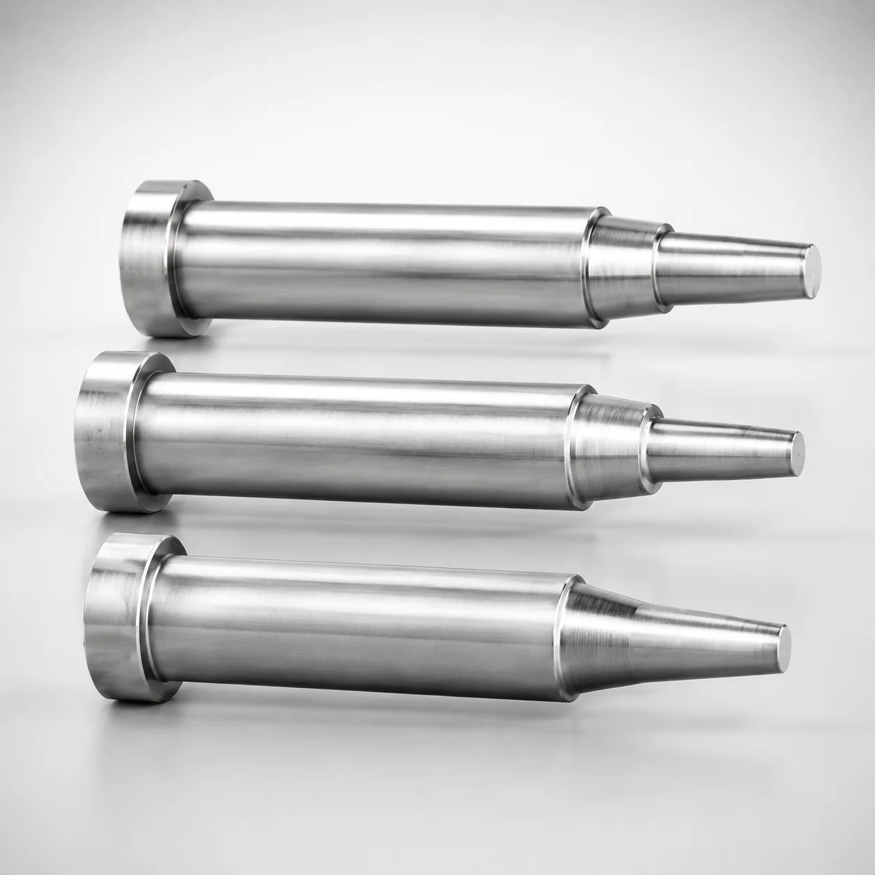
Two-Step Core Pins Head T=4 mm are designed for stable core positioning in precision molds, combining a two-step profile with a defined head thickness for reliable fit during assembly. The shaft and tip geometry support consistent guiding and repeatable alignment across production runs.
- Two-step core pin geometry for controlled seating in mold components
- Selectable hardened steel options for improved wear and abrasion resistance
- Supports tight assembly requirements with L dimension +0.02/0
- Head thickness specified at T4 (4 mm) to match engineered core layouts
Specifications
2141 configurations available
| Material | D/P (Shaft Diameter) (mm) | First Step Shape | Second Step Shape | No. (Nominal diameter) (mm) | A (Type of the first step diameter) (mm) | C (First step shape taper width) (mm) | E (Tip diameter) (mm) | F (Bearing bore length) (mm) | G (C chamfering width of the second step shape) (mm) | J (Type of the second step) (mm) | L (L dimension) (mm) | Q (Second step shape R chamfering) (mm) | R (First step type R) (mm) | V (Type of the second step) (mm) | Dimension Y (mm) | type |
|---|---|---|---|---|---|---|---|---|---|---|---|---|---|---|---|---|
| DH2F | 1 ~ 1.49 | CA | A | 1.5 | - | - | 0.5 ~ 1.48 | 10 ~ 99 | - | - | 12 ~ 100 | - | - | 0.51 ~ 1.48 | 10.5 ~ 99.5 | - |
| DH2F | 1.5 ~ 1.99 | CA | A | 2 | - | - | 0.7 ~ 1.97 | 10 ~ 99.7 | - | - | 12 ~ 100 | - | - | 0.7 ~ 1.98 | 10 ~ 99.5 | - |
| DH2F | 2 ~ 2.49 | CA | A | 2.5 | - | - | 0.7 ~ 2.47 | 10 ~ 99.7 | - | - | 12 ~ 100 | - | - | 0.7 ~ 2.48 | 10 ~ 99.5 | - |
| DH2F | 2.5 ~ 2.99 | CA | A | 3 | - | - | 1 ~ 2.97 | 10 ~ 99.7 | - | - | 12 ~ 100 | - | - | 1 ~ 2.98 | 10 ~ 99.5 | - |
| DH2F | 3 ~ 3.49 | CA | A | 3.5 | - | - | 1 ~ 3.47 | 10 ~ 99.7 | - | - | 12 ~ 100 | - | - | 1 ~ 3.48 | 10 ~ 99.5 | - |
| DH2F | 3.5 ~ 3.99 | CA | A | 4 | - | - | 1 ~ 3.97 | 10 ~ 119.7 | - | - | 12 ~ 120 | - | - | 1 ~ 3.98 | 10 ~ 119.5 | - |
| DH2F | 4 ~ 4.49 | CA | A | 4.5 | - | - | 1.5 ~ 4.47 | 10 ~ 119.7 | - | - | 12 ~ 120 | - | - | 1.5 ~ 4.48 | 10 ~ 119.5 | - |
| DH2F | 4.5 ~ 4.99 | CA | A | 5 | - | - | 1.5 ~ 4.97 | 10 ~ 119.7 | - | - | 12 ~ 120 | - | - | 1.5 ~ 4.98 | 10 ~ 119.5 | - |
| DH2F | 5 ~ 5.49 | CA | A | 5.5 | - | - | 1.5 ~ 5.47 | 10 ~ 119.7 | - | - | 12 ~ 120 | - | - | 1.5 ~ 5.48 | 10 ~ 119.5 | - |
| DH2F | 5.5 ~ 5.99 | CA | A | 6 | - | - | 2 ~ 5.97 | 10 ~ 119.7 | - | - | 12 ~ 120 | - | - | 2 ~ 5.98 | 10 ~ 119.5 | - |
| DH2F | 6 ~ 6.49 | CA | A | 6.5 | - | - | 2 ~ 6.47 | 10 ~ 119.7 | - | - | 12 ~ 120 | - | - | 2 ~ 6.48 | 10 ~ 119.5 | - |
| DH2F | 6.5 ~ 6.99 | CA | A | 7 | - | - | 2 ~ 6.97 | 10 ~ 119.7 | - | - | 12 ~ 120 | - | - | 2 ~ 6.98 | 10 ~ 119.5 | - |
| DH2F | 7 ~ 7.99 | CA | A | 8 | - | - | 2 ~ 7.97 | 10 ~ 119.7 | - | - | 12 ~ 120 | - | - | 2 ~ 7.98 | 10 ~ 119.5 | - |
| DH2F | 8 ~ 9.99 | CA | A | 10 | - | - | 2 ~ 9.97 | 10 ~ 119.7 | - | - | 12 ~ 120 | - | - | 2 ~ 9.98 | 10 ~ 119.5 | - |
| DH2F | 10 ~ 12.99 | CA | A | 13 | - | - | 2.5 ~ 12.97 | 10 ~ 119.7 | - | - | 12 ~ 120 | - | - | 2.5 ~ 12.98 | 10 ~ 119.5 | - |
| DH2F | 13 ~ 15.99 | CA | A | 16 | - | - | 2.5 ~ 15.97 | 10 ~ 119.7 | - | - | 12 ~ 120 | - | - | 2.5 ~ 15.98 | 10 ~ 119.5 | - |
| DH2F | 1 ~ 1.49 | CA | B | 1.5 | - | - | 0.5 ~ 1.48 | 10 ~ 98.8 | - | 0.5 ~ 1.48 | 12 ~ 100 | - | - | 0.51 ~ 1.48 | 10.5 ~ 99.3 | - |
| DH2F | 1.5 ~ 1.99 | CA | B | 2 | - | - | 0.7 ~ 1.97 | 10 ~ 99.7 | - | 0.7 ~ 1.97 | 12 ~ 100 | - | - | 0.7 ~ 1.98 | 10 ~ 99.5 | - |
| DH2F | 2 ~ 2.49 | CA | B | 2.5 | - | - | 0.7 ~ 2.47 | 10 ~ 99.7 | - | 0.7 ~ 2.47 | 12 ~ 100 | - | - | 0.7 ~ 2.48 | 10 ~ 99.5 | - |
| DH2F | 2.5 ~ 2.99 | CA | B | 3 | - | - | 1 ~ 2.97 | 10 ~ 99.7 | - | 1 ~ 2.97 | 12 ~ 100 | - | - | 1 ~ 2.98 | 10 ~ 99.5 | - |
| DH2F | 3 ~ 3.49 | CA | B | 3.5 | - | - | 1 ~ 3.47 | 10 ~ 99.7 | - | 1 ~ 3.47 | 12 ~ 100 | - | - | 1 ~ 3.48 | 10 ~ 99.5 | - |
| DH2F | 3.5 ~ 3.99 | CA | B | 4 | - | - | 1 ~ 3.97 | 10 ~ 119.7 | - | 1 ~ 3.97 | 12 ~ 120 | - | - | 1 ~ 3.98 | 10 ~ 119.5 | - |
| DH2F | 4 ~ 4.49 | CA | B | 4.5 | - | - | 1.5 ~ 4.47 | 10 ~ 119.7 | - | 1.5 ~ 4.47 | 12 ~ 120 | - | - | 1.5 ~ 4.48 | 10 ~ 119.5 | - |
| DH2F | 4.5 ~ 4.99 | CA | B | 5 | - | - | 1.5 ~ 4.97 | 10 ~ 119.7 | - | 1.5 ~ 4.97 | 12 ~ 120 | - | - | 1.5 ~ 4.98 | 10 ~ 119.5 | - |
| DH2F | 5 ~ 5.49 | CA | B | 5.5 | - | - | 1.5 ~ 5.47 | 10 ~ 119.7 | - | 1.5 ~ 5.47 | 12 ~ 120 | - | - | 1.5 ~ 5.48 | 10 ~ 119.5 | - |
| DH2F | 5.5 ~ 5.99 | CA | B | 6 | - | - | 2 ~ 5.97 | 10 ~ 119.7 | - | 2 ~ 5.97 | 12 ~ 120 | - | - | 2 ~ 5.98 | 10 ~ 119.5 | - |
| DH2F | 6 ~ 6.49 | CA | B | 6.5 | - | - | 2 ~ 6.47 | 10 ~ 119.7 | - | 2 ~ 6.47 | 12 ~ 120 | - | - | 2 ~ 6.48 | 10 ~ 119.5 | - |
| DH2F | 6.5 ~ 6.99 | CA | B | 7 | - | - | 2 ~ 6.97 | 10 ~ 119.7 | - | 2 ~ 6.97 | 12 ~ 120 | - | - | 2 ~ 6.98 | 10 ~ 119.5 | - |
| DH2F | 7 ~ 7.99 | CA | B | 8 | - | - | 2 ~ 7.97 | 10 ~ 119.7 | - | 2 ~ 7.97 | 12 ~ 120 | - | - | 2 ~ 7.98 | 10 ~ 119.5 | - |
| DH2F | 8 ~ 9.99 | CA | B | 10 | - | - | 2 ~ 9.97 | 10 ~ 119.7 | - | 2 ~ 9.97 | 12 ~ 120 | - | - | 2 ~ 9.98 | 10 ~ 119.5 | - |
| DH2F | 10 ~ 12.99 | CA | B | 13 | - | - | 2.5 ~ 12.97 | 10 ~ 119.7 | - | 2.5 ~ 12.97 | 12 ~ 120 | - | - | 2.5 ~ 12.98 | 10 ~ 119.5 | - |
| DH2F | 13 ~ 15.99 | CA | B | 16 | - | - | 2.5 ~ 15.97 | 10 ~ 119.7 | - | 2.5 ~ 15.97 | 12 ~ 120 | - | - | 2.5 ~ 15.98 | 10 ~ 119.5 | - |
| DH2F | 1 ~ 1.49 | CA | C | 1.5 | - | - | 0.5 ~ 1.48 | 10 ~ 99 | - | 0.5 ~ 1.48 | 12 ~ 100 | - | - | 0.51 ~ 1.48 | 10.5 ~ 99.5 | - |
| DH2F | 1.5 ~ 1.99 | CA | C | 2 | - | - | 0.7 ~ 1.97 | 10 ~ 99.7 | - | 0.7 ~ 1.97 | 12 ~ 100 | - | - | 0.7 ~ 1.98 | 10 ~ 99.5 | - |
| DH2F | 2 ~ 2.49 | CA | C | 2.5 | - | - | 0.7 ~ 2.47 | 10 ~ 99.7 | - | 0.7 ~ 2.47 | 12 ~ 100 | - | - | 0.7 ~ 2.48 | 10 ~ 99.5 | - |
| DH2F | 2.5 ~ 2.99 | CA | C | 3 | - | - | 1 ~ 2.97 | 10 ~ 99.7 | - | 1 ~ 2.97 | 12 ~ 100 | - | - | 1 ~ 2.98 | 10 ~ 99.5 | - |
| DH2F | 3 ~ 3.49 | CA | C | 3.5 | - | - | 1 ~ 3.47 | 10 ~ 99.7 | - | 1 ~ 3.47 | 12 ~ 100 | - | - | 1 ~ 3.48 | 10 ~ 99.5 | - |
| DH2F | 3.5 ~ 3.99 | CA | C | 4 | - | - | 1 ~ 3.97 | 10 ~ 119.7 | - | 1 ~ 3.97 | 12 ~ 120 | - | - | 1 ~ 3.98 | 10 ~ 119.5 | - |
| DH2F | 4 ~ 4.49 | CA | C | 4.5 | - | - | 1.5 ~ 4.47 | 10 ~ 119.7 | - | 1.5 ~ 4.47 | 12 ~ 120 | - | - | 1.5 ~ 4.48 | 10 ~ 119.5 | - |
| DH2F | 4.5 ~ 4.99 | CA | C | 5 | - | - | 1.5 ~ 4.97 | 10 ~ 119.7 | - | 1.5 ~ 4.97 | 12 ~ 120 | - | - | 1.5 ~ 4.98 | 10 ~ 119.5 | - |
| DH2F | 5 ~ 5.49 | CA | C | 5.5 | - | - | 1.5 ~ 5.47 | 10 ~ 119.7 | - | 1.5 ~ 5.47 | 12 ~ 120 | - | - | 1.5 ~ 5.48 | 10 ~ 119.5 | - |
| DH2F | 5.5 ~ 5.99 | CA | C | 6 | - | - | 2 ~ 5.97 | 10 ~ 119.7 | - | 2 ~ 5.97 | 12 ~ 120 | - | - | 2 ~ 5.98 | 10 ~ 119.5 | - |
| DH2F | 6 ~ 6.49 | CA | C | 6.5 | - | - | 2 ~ 6.47 | 10 ~ 119.7 | - | 2 ~ 6.47 | 12 ~ 120 | - | - | 2 ~ 6.48 | 10 ~ 119.5 | - |
| DH2F | 6.5 ~ 6.99 | CA | C | 7 | - | - | 2 ~ 6.97 | 10 ~ 119.7 | - | 2 ~ 6.97 | 12 ~ 120 | - | - | 2 ~ 6.98 | 10 ~ 119.5 | - |
| DH2F | 7 ~ 7.99 | CA | C | 8 | - | - | 2 ~ 7.97 | 10 ~ 119.7 | - | 2 ~ 7.97 | 12 ~ 120 | - | - | 2 ~ 7.98 | 10 ~ 119.5 | - |
| DH2F | 8 ~ 9.99 | CA | C | 10 | - | - | 2 ~ 9.97 | 10 ~ 119.7 | - | 2 ~ 9.97 | 12 ~ 120 | - | - | 2 ~ 9.98 | 10 ~ 119.5 | - |
| DH2F | 10 ~ 12.99 | CA | C | 13 | - | - | 2.5 ~ 12.97 | 10 ~ 119.7 | - | 2.5 ~ 12.97 | 12 ~ 120 | - | - | 2.5 ~ 12.98 | 10 ~ 119.5 | - |
| DH2F | 13 ~ 15.99 | CA | C | 16 | - | - | 2.5 ~ 15.97 | 10 ~ 119.7 | - | 2.5 ~ 15.97 | 12 ~ 120 | - | - | 2.5 ~ 15.98 | 10 ~ 119.5 | - |
| DH2F | 1 ~ 1.49 | CA | D | 1.5 | - | - | 0.5 ~ 1.48 | 10 ~ 98.9 | 0.1 ~ 0.5 | 0.5 ~ 1.48 | 12 ~ 100 | - | - | 0.51 ~ 1.48 | 10.5 ~ 99.4 | - |
| DH2F | 1.5 ~ 1.99 | CA | D | 2 | - | - | 0.7 ~ 1.97 | 10 ~ 99.7 | 0.1 ~ 0.5 | 0.7 ~ 1.97 | 12 ~ 100 | - | - | 0.7 ~ 1.98 | 10 ~ 99.5 | - |
Product Guide
Application Scenarios+
Two-step core pins are used in injection mold tooling to ensure repeatable alignment between the core and cavity halves during assembly and clamping cycles.
- Automotive connector and sensor housing molds: Use the defined head thickness (T=4 mm) and controlled two-step seating to maintain core position under vibration and high clamp-force repeatability, especially when fine positional stability is required between multiple locating features.
- Medical device housings and precision housings: The guided shaft and tip geometry support consistent positioning for thin-wall or high-tolerance parts, helping reduce drift and ensuring the mold’s core-to-cavity offset remains stable across production runs.
- Industrial appliance and electronics enclosure molds: When wear from repeated cycling is a concern, select a suitable hardened steel option from the available materials to improve abrasion resistance at the contact and bearing bore interface.
This variant is suited to applications where locating repeatability and controlled seating are critical, and where the T=4 mm head thickness must match engineered core layouts.
Material & Process Details+
This core pin series supports selectable steel options tailored to wear and toughness needs during repeated mold cycles. Available materials include DH2F, SKH51, NAK80, SKD61, SUS440C, and MAS1C.
- SKH51 is an AISI M2 equivalent high-speed steel typically used for superior wear resistance; it is known for high hardness, with a common manufacturing outcome in the ~HRC 60+ range depending on heat treatment.
- SKD61 is commonly treated as an H13 equivalent tool steel, offering a balance of toughness and hot-work capability; parts are usually quenched & tempered to achieve a hardened condition with good impact resistance compared with higher-carbon wear steels.
- NAK80 is often selected for corrosion resistance and dimensional stability in molds, while SUS440C provides strong wear performance with good hardness after hardening.
Material selection typically trades wear resistance (higher-hardened alloys) against toughness and resistance to edge chipping (more balanced tool steels). Final hardness and wear behavior depend on the supplier’s heat treatment route for the chosen grade.
Sizing & Selection Guide+
To select the correct dimensions for this two-step core pin, match its diameter, steps, and length to the mold’s core positioning and locating features.
- Shaft diameter (D/P): Choose from 1 ~ 16 mm to match the required hole/bearing bore size. Nominal diameter range is 1.5 ~ 20 mm depending on configuration.
- Overall length (L): Select L = 11 ~ 30 mm so the pin properly guides and supports seating without over-insertion.
- Step geometry: Pick the first step shape (CA/CB/CC/CD/CE) and second step shape (A/B/C/D/E) that correspond to your core layout. The tip diameter (E) is 0.5 ~ 5 mm, and the first-step diameter type A is 0.5 ~ 5.01 mm.
- Bearing bore length (F): Use F = 10 ~ 30 mm to ensure stable contact in the locating zone.
Maintain assembly-fit control: the design references L dimension +0.02/0, so confirm that your cavity/core seating stack-up and any locating clearances align with this tolerance requirement. Configure step shapes and chamfers (e.g., G and related parameters) to reproduce the intended seating profile.
Frequently Asked Questions
Which dimension is critical for ensuring stable core seating—L tolerance or step geometry?+
How do I choose the shaft diameter (D/P) relative to the mold bearing bore?+
What materials should I prefer for wear resistance versus toughness?+
How do I select the tip diameter E and first-step diameter type A to fit thin locating features?+
What does the fixed head thickness T=4 mm imply for compatibility with my core layout?+
Related Products
Need Custom Specifications?
Our engineering team can help with custom configurations, material selection, and volume pricing.